Electrospun porous CuCo2O4 nanowire network electrode for asymmetric supercapacitors†
Qiufan Wang*a,
Di Chenb and
Daohong Zhang*a
aKey Laboratory of Catalysis and Materials Science of the State Ethnic Affairs Commission & Ministry of Education, South-Central University for Nationalities, Wuhan, Hubei Province 430074, China. E-mail: YGDF@mail.scuec.edu.cn; Zhangdh27@163.com
bSchool of Mathematics and Physics, University of Science and Technology Beijing, Beijing 100083, China. E-mail: chendi@ustb.edu.cn
First published on 4th November 2015
Abstract
Porous network nanostructures have been demonstrated as one of the most ideal electrode materials in energy storage systems due to their advantages of both microstructures and their high surface area. In this study, a facile electrospinning method with subsequent heat treatments is employed to firstly prepare a CuCo2O4 network structure. The CuCo2O4 network electrode delivers a remarkable areal capacitance of 443.9 mF cm−2 at a current density of 1 mA cm−2. The electrode also presents excellent cyclic stability of 90% capacity retention after 1500 cycles at 1 mA cm−2. We have successfully fabricated a high-performance asymmetric supercapacitor based on the CuCo2O4 network nanostructure and active carbon as positive and negative materials, respectively. The assembled novel asymmetric supercapacitor device with an extended operating voltage window of 1.5 V exhibits excellent performance such as a high energy density of 0.806 mW h cm−3 and good rate capability. The high-performance nanostructured CuCo2O4 has significant potential applications in electrical vehicles.
Introduction
Due to the rapidly growing global energy consumption and worsening environmental pollution, the development of green power sources has become an urgent and increasing demand in various fields such as electric vehicles, hybrid electric vehicles, and other power-supply devices.1,2 Among various energy storage devices, supercapacitors, with high power density, fast charge/discharge rate, and long lifespan, are typically considered as one of the most appropriate choices for energy storage devices.3–5 In order to meet the increasing energy density demands for next generation electronic devices, the energy density of supercapacitors needs to be further improved. According to the equation of energy density (E = 0.5CV2), the specific energy density can be improved by increasing the output voltage and/or the specific capacitance.6,7 Asymmetric supercapacitor can combine a battery-tape faradaic electrode and a capacitor-type electrode to increase the output voltage. Thus, developing appropriate electrode materials has become the essential part of the current endeavor to boost the energy densities of asymmetric supercapacitors.8–11Among the multitudinous available pseudocapacitive materials, transition metal oxides are considered especially promising as electrode materials, due to their multiple oxidation state, excellent intrinsic properties and good electrochemical performance.12,13 Building the porous 3D nanostructure is a promising solution to achieve high capacitance. From a wide range of pseudocapacitive materials, spinel oxides have a high electronic/ionic conductivity and catalytic activity, that are of great interest for energy storage applications.14–17 We have got some important achievements in this area,13,17 a core/shell CuCo2O4@MnO2 heterostructured nanowire array on carbon fabrics have been firstly fabricated as electrode for symmetric supercapacitor, and a maximum specific capacitance of 327 F g−1 was achieved.18
CuCo2O4 (CCO) is a binary spinel metal oxide with great electronic conductivity and electrochemical activity than single-component copper or cobalt oxide. Recently research on nanostructured materials has demonstrated enhanced capacitive performance, because of their high surface area, short ion-diffusion path, and fast kinetics. Therefore, rationally designed the morphology and/or structure provides one of the most feasible ways to create high performance supercapacitors. Wang et al. synthesized grass-like CuCo2O4 nanowire arrays on Ni foam to achieve a high area capacitance of 611 F g−1 at current density of 1.7 A g−1.19 Luo et al. recently reported mesoporous CuCo2O4 nanograsses on copper foam with an excellent specific capacitance of 796 F g−1 at a current density of 2 A g−1.20 Compared with the above processes, electrospinning is a cost-effective, versatile, and simple way to fabricate well-defined 3D nanostructures.
Herein, we firstly propose and realize a facile, effective, and scalable strategy for preparing spinel-based porous CuCo2O4 network by combing the electrospinning technique with a heating method. The new network CuCo2O4 structure is firstly investigated as the supercapacitor electrode materials. Electrochemical measurements show that this network electrode can exhibit excellent specific capacitance as high as 443.9 mF cm−2. Then, we fabricate asymmetric supercapacitors with CuCo2O4 and active carbon as two electrodes for practical applications. It is found that this asymmetric supercapacitor could deliver a high energy density of 0.806 mW h cm−3 at power density of 7.8 mW cm−3, and good rate capability. The high-performance CuCo2O4 nanostructures may have significant potential applications in electrical vehicles.
Experimental
Synthesis of CuCo2O4 nanowire networks
All chemical reagents were used of analytical grade and were used directly without any purification. In a typical procedure, poly(vinylpyrrolidone) (PVP, MW = 130![[thin space (1/6-em)]](https://www.rsc.org/images/entities/char_2009.gif) 000 g mol−1) was dissolved in a mixture of ethanol (5 mL) and N,N-dimethylformamide (DMF, 5 mL) with vigorous stirring to form a 10 wt% solution. Then, 0.4748 g Co(NO3)2·6H2O and 0.1128 g Cu(NO3)2·6H2O were added in the above solution. After stirring at room temperature for 12 h, the precursor solution was obtained. Subsequently, the above precursor solution was drawn into a hypodermic syringe. The positive terminal of a variable high-voltage power supply was connected to the needle tip of the syringe, while the other terminal was connected to the collector plate. With a flow rate of 1 mL h−1 and an applied voltage of 18 kV between the needle tip and aluminum collector with a distance of 15 cm, the as-prepared solution was electrospun into nanowires. Afterward, the above spun nanowires were sintered at 500 °C for 3 h at a rate of 2 °C min−1 in air.
000 g mol−1) was dissolved in a mixture of ethanol (5 mL) and N,N-dimethylformamide (DMF, 5 mL) with vigorous stirring to form a 10 wt% solution. Then, 0.4748 g Co(NO3)2·6H2O and 0.1128 g Cu(NO3)2·6H2O were added in the above solution. After stirring at room temperature for 12 h, the precursor solution was obtained. Subsequently, the above precursor solution was drawn into a hypodermic syringe. The positive terminal of a variable high-voltage power supply was connected to the needle tip of the syringe, while the other terminal was connected to the collector plate. With a flow rate of 1 mL h−1 and an applied voltage of 18 kV between the needle tip and aluminum collector with a distance of 15 cm, the as-prepared solution was electrospun into nanowires. Afterward, the above spun nanowires were sintered at 500 °C for 3 h at a rate of 2 °C min−1 in air.
Fabrication of working electrode
The working electrode was prepared by mixing the as-prepared CuCo2O4 nanowire network (or active carbon), acetylene black, and polyvinylidene fluoride (PVDF) binder with a weight ratio of 70![[thin space (1/6-em)]](https://www.rsc.org/images/entities/char_2009.gif) :
:![[thin space (1/6-em)]](https://www.rsc.org/images/entities/char_2009.gif) 20
20![[thin space (1/6-em)]](https://www.rsc.org/images/entities/char_2009.gif) :
:![[thin space (1/6-em)]](https://www.rsc.org/images/entities/char_2009.gif) 10, which were pasted onto a treated nickel foam and dried under a vacuum at 100 °C for 5 h to remove NMP.
10, which were pasted onto a treated nickel foam and dried under a vacuum at 100 °C for 5 h to remove NMP.
Fabrication of CuCo2O4//active carbon asymmetric supercapacitors
The fabrication of the CuCo2O4//active carbon (AC) asymmetric supercapacitors was conducted by taking the CuCo2O4 network and AC as positive and negative electrodes, respectively. A 3 M KOH solution was used as the electrolyte, and a glass membrane as the separator in two-electrode simulation cells. The thickness of the device was measured to be 1 mm, including the electrodes and the separator.Electrochemical measurements
The electrochemical tests were carried out at room temperature in both three-electrode and two-electrode configurations. In the three-electrode system, the as-prepared CuCo2O4 positive electrode (or active carbon negative electrode), a platinum electrode, and a saturated calomel electrode (SCE) were used as the working electrode, counter electrode, and reference electrode, respectively. A 3 M KOH solution was used as electrolyte for all electrochemical measurements. The electrochemical performances were measured with an electrochemical workstation (CHI760D). The electrochemical properties and capacitive behavior of the electrochemical properties and capacitive behavior of the supercapacitor electrodes were evaluated by cyclic voltammetry (CV) and galvanostatic charge–discharge (CD). EIS measurements were carried out in the frequency range from 0.01 Hz to 100 KHz.The calculation of energy and power density is based on the total weight of the two electrodes in the full-cell devices according to the following equations.
Calculations
The energy density (W h cm−3) and power density (W cm−3) derived from galvanostatic charge/discharge curves are estimated by following equations:| E = C × ΔV2/(2ΔV × 3600) | (1) |
| P = E × 3600/Δt | (2) |
Materials characterizations
The synthesized products were characterized with an X-ray diffractometer (XRD; X'Pert PRO, PANalytical B. V., the Netherlands) with radiation from a Cu target (Kα, λ = 0.15406 nm). The morphologies of the samples were characterized using electron microscopy (FESEM; JEOL JSM-6700F, 5 kV) and transmission electron microscopy (HRTEM; JEOL JEM-2010 HT) coupled with an energy-dispersive X-ray spectrometer (EDX).Results and discussion
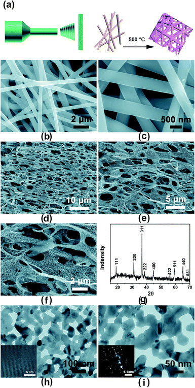
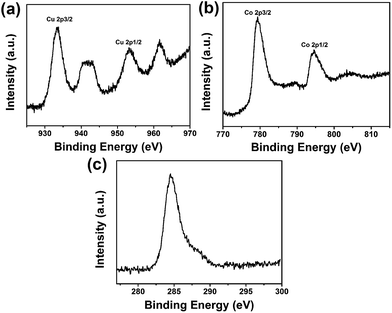
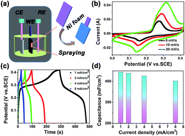
Fig. 1a schematically illustrates the facile synthetic process of CuCo2O4 network nanostructures. The morphology and detailed structural information are determined by scanning electron microscopy (SEM) and transmission electron microscopy (TEM). Fig. 1b and c show the as-spun nanofibers before the calcination. It could be observed that these nanowires have a smooth and uniform surface. Their lengths could reach dozens of micrometers, and the diameter ranged from 450 to 500 nm. After calcination in air for 3 h, the CuCo2O4 webs maintain the interconnected porous network microstructure as shown in Fig. 1d–f. Fig. 1h and i show the TEM images of the network structure, which reveal clearly that the network is composed by a large amount of connect nanocrystallites with sizes of 30–50 nm. A lot of uniform separated nanopores exist among these nanoparticles and are absolutely penetrated. In order to obtain the microstructure of CuCo2O4 nanowire network, the high-resolution transmission electron microscopy (HRTEM) observations were carried out, and the corresponding results are shown in the inset of Fig. 1g. The diffraction ring pattern of the selected-area electron diffraction (SAED) indicates the polycrystalline assembling nature of the network (inset of Fig. 1h). X-ray photoelectron spectroscopy (XPS) survey spectrums of the Cu, Co and O element show in Fig. 2. The XPS Cu 2p and Co 2p spectra indicate that copper exist in the Cu2+ state and cobalt has a spinel structure.21The electrochemical properties of CuCo2O4 nanowire network electrode material for SC were performed with three-electrode test system (Fig. 3a). Fig. 3b shows representative CV curves of CuCo2O4 network structure in a aqueous electrolyte of 3 M KOH from 0 to 0.42 V (vs. SCE). A pair of strong redox peaks were visible in each voltammogram indicating that the capacitance characteristics are mainly governed by faradaic redox reactions. At a low scan rate of 5 mV s−1, the anodic peak at 0.276 V is due to the oxidation process, and the cathodic peak at about 0.158 V is related to its reverse process. A possible mechanism is that by initiating the scan from cathodic potentials, CoOOH22a and CuOH may form at the outer surface of the CuCo2O4 electrode, according to the following equation:22c
| CuCo2O4 + H2O + e− ↔ 2CoOOH + Cu(OH)− | (3) |
Then, by sweeping the potential toward positive values, redox reactions occur as follows:
| CoOOH + OH− ↔ CoO2 + H2O + e− | (4) |
| CuOH + OH− ↔ Cu(OH)2 + e− | (5) |
The peak current increases linearly with the scan rate, suggesting that the rates of electronic and ionic transport should be rapid enough in the applied scan rates. Fig. 3c shows the galvanostatic charge/discharge curves at different current densities ranging from 1 to 8 mA cm−2.
The specific capacitance C (mF cm−2), one of the most important parameters for characterizing the electrochemical performance of capacitors, can be calculated from the discharge curve according to C = IΔt/(SΔV) (mF cm−2). Where I is the discharge current, Δt is the discharge time, S is the area of the active material and ΔV is the potential window during discharge curve.
The areal capacitance versus discharge current density is plotted in Fig. 3d. The specific capacitances of the CuCo2O4 network are calculated to be 443.9, 439, 426 and 402 mF cm−2, at current densities of 1, 2, 4 and 8 mA cm−2. With increasing current density, the specific capacitance decreases gradually, we can obtain the specific capacitance of 402 mF cm−2 for the CuCo2O4 network at high current density of 8 mA cm−2, representing only 9.5% decrease compared with the specific capacitance of 443.9 mF cm−2 at a current density of 1 mA cm−2, which is comparable with the previous report,22b and lower than the binder-free NiMoO4 nanoplate arrays-based asymmetric supercapacitor,22d and CoMoO4 nanosheet.22e This result indicates the excellent capacitive behavior and high-rate capability of the CuCo2O4 network nanostructure.
The superior electrochemical performance of CuCo2O4 electrode can be attributed to the network structure providing large accessible surface area, fast ion and electron transfer, and good structural stability. Significantly, the excellent capacitive behaviors demonstrate that the as-prepared network CuCo2O4 will be a promising candidate as a positive electrode for asymmetric supercapacitors.
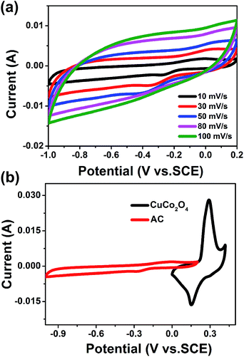
To identify the potential window of asymmetric supercapacitor and balance the charges between positive and negative electrodes, we also investigate the electrochemical performance of active carbon electrode in a three-electrode system. The active carbon electrode shows a potential window of −1 V to 0.2 V, Fig. 4a demonstrates the CV curves of AC electrode at different scan rates. Fig. 4b shows the comparison of CV curves for two electrodes at a scan rate of 10 mV s−1. To achieve the optimized performance of the asymmetric device, the optimal mass ratio of positive and negative electrode is fixed to around 0.65![[thin space (1/6-em)]](https://www.rsc.org/images/entities/char_2009.gif) :
:![[thin space (1/6-em)]](https://www.rsc.org/images/entities/char_2009.gif) 1, which is based on the charge balance between the two electrodes.
1, which is based on the charge balance between the two electrodes.
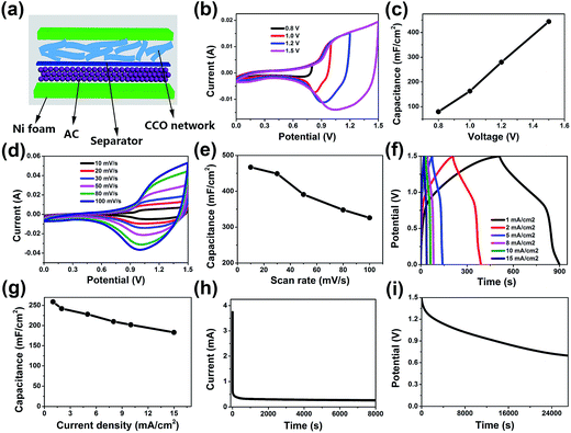
To further evaluate the CuCo2O4 network electrode for practical application, a simple asymmetric supercapacitor device is manufactured by using the CuCo2O4 and active carbon electrodes. Fig. 5a displays the schematic illustration for the device. Fig. 5b demonstrates the CV curves collected at 30 mV s−1 in different voltage windows for the CuCo2O4//AC ASC. The calculated values of specific capacitance are displayed in Fig. 5c as a function of operating voltage window. A series of CV measurements at different scan rates from 10 to 100 mV s−1 is displayed in Fig. 5d. The current increases with the scan rate increasing, but the shape is well retained, indicating its ideal capacitive nature. The gradual fall of specific capacitance with increasing scan rate is clearly apparent form Fig. 5e, which is the consequence of diffusion limits in charge transport at higher scan rates. The specific capacitance increases from 326 mF cm−2 to 467 mF cm−2 with the scan rate from 100 to 10 mV s−1.
Fig. 5f demonstrate the galvanostatic charge/discharge measurements, which are carried out at different current densities in the potential window of 0–1.5 V. The specific capacitances are calculated at different current densities and plotted in Fig. 5g. The device shows an excellent rate capability and the areal capacitance can still be maintained at 183 mF cm−2 even when the current density increased 15 times from 1 to 15 mA cm−2, which is higher than the reported value of NiO//rGO-based ASC.27 Meanwhile, our fabricated asymmetric supercapacitor reveals a low leakage current of 0.26 mA (Fig. 5h), and an open circuit voltage of 0.7 V can be maintained for 7.44 h after charged at 1.5 V (Fig. 5i).
The Nyquist plot in Fig. 6a represents excellent electrical conductivity of the device with a very small cell resistance shown at a high frequency range. The disappearance of the semicircle in the Nyquist plot in a high frequency range exhibited very small charge/discharge resistance of the device, which is probably ascribed to the integrated 3D electrodes that minimize the contact impedance between electrodes and electrolyte.
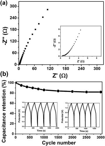 | ||
| Fig. 6 (a) Nyquist plots for asymmetric device. (b) Cycling performance of the asymmetric device. The inset were the charge/discharge curves for the first and last five cycles. | ||
The long-term cycling performance is one of the most critical factors to determine the energy storage performance for supercapacitor operations. The cycling test of our asymmetric devices is evaluated in the 1.5 V voltage window at a current density of 2 mA cm−2 for 3000 cycle (Fig. 6b), it shows about 82% capacitance retention, which is significantly better than those reported in previous work (typical 70–85% retention over 3000 cycle).23–26 The capacity decay after long-term cycling for our asymmetric device may due to the mechanical failure of the CuCo2O4 electrode, resulting in the delamination of the active materials from the Ni foam substrate.
The energy and power densities are two key parameters in characterizing the performances of supercapacitors. Fig. 7 shows the Ragone plot of our asymmetric supercapacitors. The maximum energy density of the prepared ASC is 0.81 mW h cm−3 at a power density of 7.48 mW cm−3. These values are superior to the previously reported supercapacitor systems, including ZnO@MnO2//rGO-based SCs (0.234 mW h cm−3, 5 mW cm−3),28 H–TiO2@MnO2//H–TiO2@C-based ASCs (0.3 mW h cm−3 at 0.2 W cm−3),29 and CNT-based supercapacitors with 0.13 mW h cm−3 at 0.73 W cm−3,30 also are about 9-fold higher than graphene-based SCs (0.09 mW h cm−3 at 0.1 W cm−3)31 The excellent performance can attribute to the large surface area that leads to sufficient ion transfer on electrode/electrolyte interface, also the nanopores on the surface can supply facile transport channel for OH− ions. On the other hand, the interconnected webs provide a continuous pathway for electron transport. The high energy and power densities of our asymmetric supercapacitors are of great promise of practical energy storage applications.
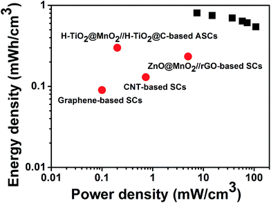 | ||
| Fig. 7 Ragone plots of the asymmetric supercapacitor based on the full cell. The values reported for other supercapacitors are added for comparison. | ||
Conclusions
In summary, a facile electrospinning method is used to fabricate the CuCo2O4 network structure. The CuCo2O4 network on the Ni foam substrate serve as an excellent three-dimensional supercapacitor electrode, showing a specific capacitance and excellent rate capability and conductivity. Furthermore, the asymmetric supercapacitor fabricated by the optimized CuCo2O4 network as positive electrode and active carbon as negative electrode demonstrates outstanding electrochemical performance. Our asymmetric supercapacitor shows high energy and power density, as well as robust long-term cycling stability. The performance we achieved suggests that the ternary CuCo2O4 prepared by electrospinning process have great potential in various energy storage technologies.Acknowledgements
We gratefully acknowledge the financial support of Hubei Province Natural Science Fund for Distinguished Young Scientists (2014CFA037).Notes and references
- J. R. Miller and P. Simon, Science, 2008, 321, 651 CrossRef CAS PubMed.
- K. S. Kang, Y. S. Meng, J. Breger, C. P. Grey and G. Ceder, Science, 2006, 311, 977 CrossRef CAS PubMed.
- (a) H. Zhao, C. Wang, R. Vellacheri, M. Zhou, Y. Xu, Q. Fu, M. Wu, F. Grote and Y. Lei, Adv. Mater., 2014, 26, 7654 CrossRef CAS PubMed; (b) D. Zhang, M. Miao, H. Niu and Z. Wei, ACS Nano, 2014, 8, 4571–4579 CrossRef CAS PubMed.
- (a) J. Zhao, H. Lai, Z. Lyu, Y. Jiang, K. Xie, X. Wang, Q. Wu, L. Yang, Z. Jin, Y. Ma, J. Liu and Z. Hu, Adv. Mater., 2015, 27, 3541 CrossRef CAS PubMed; (b) C. Z. Yuan, L. Yang, L. R. Hou, L. F. Shen, X. G. Zhang and X. W. Lou, Energy Environ. Sci., 2012, 5, 7883–7887 RSC.
- E. Lim, H. Kim, C. Jo, J. Chun, K. Ku, S. Kim, H. I. Lee, I.-S. Nam, S. Yoon, K. Kang and J. Lee, ACS Nano, 2014, 8, 8968 CrossRef CAS PubMed.
- P. C. Chen, G. Z. Shen, Y. Shi, H. Chen and C. W. Zhou, ACS Nano, 2010, 4, 4403–4411 CrossRef CAS PubMed.
- J. Xu, Q. F. Wang, X. W. Wang, Q. Y. Xiang, B. Liang, D. Chen and G. Z. Shen, ACS Nano, 2013, 7, 5453–5462 CrossRef CAS PubMed.
- N. S. Choi, Z. H. Chen, S. A. Freunberger, X. L. Ji, Y. K. Sun, K. Amine, G. Yushin, L. F. Nazar, J. Cho and P. G. Bruce, Angew. Chem., Int. Ed., 2012, 51, 9994 CrossRef CAS PubMed.
- J. B. Goodenough and K. S. Park, J. Am. Chem. Soc., 2013, 135, 1167 CrossRef CAS PubMed.
- L. W. Ji, Z. Lin, M. Alcoutlabi and X. W. Zhang, Energy Environ. Sci., 2011, 4, 2682 CAS.
- L. Yu, L. Zhang, H. B. Wu, G. Q. Zhang and X. W. Lou, Energy Environ. Sci., 2013, 6, 2664–2671 CAS.
- V. Augustyn, P. Simon and B. Dunn, Energy Environ. Sci., 2014, 7, 1597 CAS.
- Q. F. Wang, X. F. Wang, B. Liu, G. Yu, X. J. Hou, D. Chen and G. Z. Shen, J. Mater. Chem. A, 2013, 1, 2468–2473 CAS.
- (a) J. Zhu and Q. Gao, Microporous Mesoporous Mater., 2009, 124, 144 CrossRef CAS; (b) C. Guan, J. P. Liu, C. W. Cheng, H. X. Li, W. W. Zhou, H. Zhang and H. J. Fan, Energy Environ. Sci., 2011, 4, 4496–4499 RSC.
- G. Zhang and X. W. Lou, Sci. Rep., 2013, 3, 1470 Search PubMed.
- J. Li, S. Xiong, X. Li and Y. Qian, Nanoscale, 2013, 5, 2045 RSC.
- Q. F. Wang, B. Liu, X. F. Wang, S. H. Ran, L. M. Wang, D. Chen and G. Z. Shen, J. Mater. Chem., 2012, 22, 21647–21653 RSC.
- Q. F. Wang, J. Xu, X. F. Wang, B. Liu, X. J. Hou, G. Yu, P. Wang, D. Chen and G. Z. Shen, ChemElectroChem, 2014, 1, 559–564 CrossRef.
- H. Y. Chen, X. H. Chen, Y. Zeng, S. L. Chen and J. D. Wang, RSC Adv., 2015, 5, 70494–70497 RSC.
- J. B. Cheng, H. L. Yan, Y. Lu, K. W. Qiu, X. Y. Hou, J. Y. Xu, L. Han, X. M. Liu, J. K. Kim and Y. S. Luo, J. Mater. Chem. A, 2015, 3, 9769–9776 CAS.
- J. Jia, X. Li and G. Chen, Electrochim. Acta, 2010, 55, 8197–8206 CrossRef CAS.
- (a) M. D. Koninck and B. Marsan, Electrochim. Acta, 2008, 53, 7012 CrossRef; (b) J. P. Liu, J. Jiang, C. W. Cheng, H. X. Li, J. X. Zhang, H. Gong and H. J. Fan, Adv. Mater., 2011, 23, 2076–2081 CrossRef CAS PubMed; (c) A. Pendashteh, S. E. Moosavifard, M. S. Rahmanifar, Y. Wang, M. F. El-Kady, R. B. Kaner and M. F. Mousavi, Chem. Mater., 2015, 27(11), 3919–3926 CrossRef CAS; (d) L. Huang, J. W. Xiang, W. Zhang, C. J. Chen, H. H. Xu and Y. H. Huang, J. Mater. Chem. A, 2015, 3, 22081–22087 Search PubMed; (e) D. Guo, H. M. Zhang, X. Z. Yu, M. Zhang, P. Zhang, Q. H. Li and T. H. Wang, J. Mater. Chem. A, 2013, 1, 7247–7254 RSC.
- Y. H. Li, L. J. Cao, L. Qiao, M. Zhou, Y. Yang, P. Xiao and Y. H. Zhang, J. Mater. Chem. A, 2014, 2, 6540–6548 CAS.
- S. Abouali, M. A. Garakani, B. Zhang, Z. L. Xu, E. K. Heidari, J. Q. Huang, J. Q. Huang and J. K. Kim, ACS Appl. Mater. Interfaces, 2015, 7, 13503–13511 CAS.
- Z. S. Wu, W. Ren, D. Wang, F. Li, B. Liu and H. M. Cheng, ACS Nano, 2010, 4, 5835–5842 CrossRef CAS PubMed.
- S. Chen, J. Zhu, X. Wu, Q. Han and X. Wang, ACS Nano, 2010, 4, 2822–2830 CrossRef CAS PubMed.
- X. C. Ren, C. L. Guo, L. Q. Xu, T. T. Li, L. F. Hou and Y. H. Wei, ACS Appl. Mater. Interfaces, 2015, 7, 19930–19940 CAS.
- W. Zilong, Z. Zhu, J. Qiu and S. Yang, J. Mater. Chem. C, 2014, 2, 1331–1336 RSC.
- X. Lu, M. Yu, G. Wang, T. Zhai, X. Xie, Y. Ling, Y. X. Tong and Y. Li, Adv. Mater., 2012, 25, 267–272 CrossRef PubMed.
- Y. J. Kang, H. Chung, C. H. Han and W. Kim, Nanotechnology, 2012, 23, 065401 CrossRef PubMed.
- M. F. El-Kady, V. Strong, S. Dubin and R. B. Kaner, Science, 2012, 335, 1326–1330 CrossRef CAS PubMed.
Footnote |
| † Electronic supplementary information (ESI) available. See DOI: 10.1039/c5ra21170k |
| This journal is © The Royal Society of Chemistry 2015 |

