Ultrafast UV response detectors based on multi-channel ZnO nanowire networks†
PeiPei He‡
ab,
Shuanglong Feng‡a,
Shuangyi Liua,
Qikun Lia,
Jiwei Qic,
Zhaoyao Zhana,
Xin Lia,
Zhenhu Lia,
Jun Shen*b and
Wenqiang Lu*a
aChongqing Key Laboratory of Multi-Scale Manufacturing Technology, Chongqing Institute of Green and Intelligent Technology, Chinese Academy of Sciences, Chongqing 400714, PR China
bCollege of Materials Science and Engineering, Chongqing University, Chongqing, 400044, PR China
cInstitute of TEDA Applied Physics, School of Physics, Nankai University, Tianjin, 300071, PR China
First published on 26th November 2015
Abstract
An UV detector based on multi-channel three dimensional ZnO nanowire networks was fabricated via a catalyst-free CVD method. The ultrafast response time of 20 ms for UV detection was tested in detail. The result revealed that the formation of multi-channels on lateral growth ZnO nanowire arrays can construct a transmission path for UV excited electrons, which is essential for gaining outstanding UV detecting performance. This work not only reports a new way to fabricate in situ nanowire network UV sensors on a chip with large-scale periodic microstructures and a single optical-lithography step via a catalyst free and well controlled synthesis method, but it also confirms a novel mechanism for achieving ultrafast UV detection.
Introduction
Ultraviolet light is a double-edged sword for human beings. Both utilization of and protection against UV light are strongly dependent on fast and effectively sensoring or detecting to UV light. Zinc oxides (ZnO) are candidate semiconductors for UV detectors because of the perfect matching between the ZnO bandgap and UV photon energy. Instead of the slow response ZnO film based UV detectors, one dimensional (1D) ZnO nanostructures, such as nanowires/nanobelts,1 nanorings,2 nanohelices3 and nanotubes,4 are being paid more attention for making faster response detectors because their larger surface-to-volume ratio and reduced active area are beneficial for a fast response to UV light. Moreover, good biocompatibility and mechanical robustness of 1D ZnO nanostructures are also desirable characteristics for making high quality detectors with broader applications.Recently, the in situ lateral growth of 1D ZnO nanostructures is being studied due to the simplicity of the device preparation process (the direct bridging of electrodes by in situ growth of 1D nanostructures avoids complex semiconductor fabrication and limitations) and promised sensitivity enhancement under the function of the Schottky contact. Kind et al. reported highly sensitive 1D lateral individual ZnO based UV light switches with very good photoconduction.5 Li et al. also fabricated an in situ bridging photoconductive UV detector by the lateral growth of ZnO with high sensitivity and a broad detection band range.6
Cross-connected ZnO nanowire networks are another possible nanostructure for shortening the response time.7 Gao et al. synthesized three dimensional (3D) interconnected ZnO nanowire and nanorod networks using high temperature solid-vapor deposition, and proved that the sintered ordering cross-nanowire networks are very beneficial for ultrasensitive sensing.8 Very recently, K. Alenezi et al. reported a controlled, seedless and site selective hydrothermal technique to fabricate high performance 1D ZnO nanowire arrays based on chip UV detectors with an ultrafast response time of 90 ms.9 In terms of the aforementioned developments, UV detectors with faster response times might be achieved by the in situ synthesis of ZnO nanostructures with appropriate morphologies through a simple and economic method, which also deserves to be pursued for the mass production of high quality devices.
Here, an in situ ultrafast response (20 ms) UV detector based on novel 1D ZnO nanostructure is reported. To the best of our knowledge, the attained response time of the present case is very fast compared to other techniques, with the exception of that obtained using femtosecond laser excitation. Moreover, such a morphology with exciting properties is achieved by a simple and catalyst free CVD method.
Results and discussion
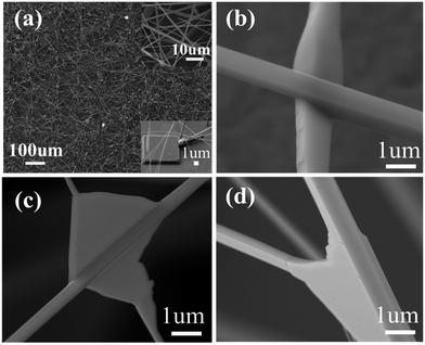
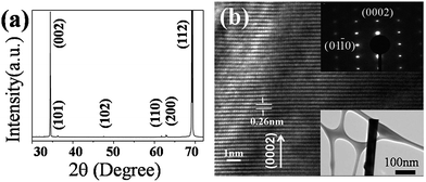
The morphologies of the as-synthesized ZnO multi-channel nanowire networks are shown in Fig. 1. The top and bottom insets of Fig. 1a are magnified images of the nanowire networks and a pre-fabricated square convex plate upon which the ZnO nanowire networks are grown, respectively. The as-synthesized nanowires are about 100 μm in length and 200–500 nm in diameter. The networks are composed of perfect crystalline ZnO nanowires (Fig. 1b–d) with cross and triple channels due to the contact of the ZnO nanowires with each other during the growth process. Further XRD and TEM characterizations in Fig. 2 show a typical ZnO wurtzite structure (a = 3.249 Å, c = 5.206 Å) and confirm that (002) peaks are the main peak, which indicates that all of the ZnO nanostructures have a highly preferred (002) orientation.The lateral grown nanowire that come into contact with each other on the top edges of the square convex plates were firstly fabricated before making the device. The reason for the lateral growth of ZnO is easy to understand, and is due to the vapor–solid process instead of the vapor–liquid–solid process, resulting in a concentration of vapor around the top edges of the plates that is much higher than that on the surface, due to the higher binding energy on the top edges of the plates.10–12
The local concentration of Zn vapor clusters and high binding surface energy at the top edge of the square convex plates are the key driving forces that guide the ZnO to nucleate and grow as nanowires on the edge instead of the surface.13,14 The convex plate arrays are used to distribute Zn vapor clusters around them to form the nanowire networks. It should be noted that the pre-fabricated convex plate arrays are necessary for forming multi-channels.
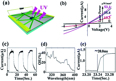
The lateral growth ZnO nanowire networks with a larger light receiving surface possess high sensitivity and an ultrafast response to UV.15–18 The multi-channels, in which inter-contact junctions of different nanowires are formed, are also expected to further shorten the response time. In order to investigate the UV detection performance, a ZnO nanowire network based detector was fabricated as shown in Fig. 3a. Fig. 3b shows I–V curves for the detector before and after illumination using a 375 nm wavelength laser with varied power density. Fig. 3c is the on–off ratio curve. Fig. 3d shows the quantum efficiency of the sensor in the wavelength range of 300 nm to 400 nm and under 2 V bias. A 28% efficiency for 375 nm UV exiting light is obtained which is similar to that of GaN based photodetectors.
A remarkably enhanced photocurrent was gained when the laser power was increased. The detector exhibited a photocurrent of 2.23 × 10⁻⁶ A at 1 V under 53.1 μW mm−2 power using 375 nm laser UV illumination. The response, R, of the detector at 1 V corresponds to a dark current of 1.3 × 10⁻⁷ A and is 42.0 mA W−1, given by the relation:
| R = Iph/Popt |
When light powers of 13.3 μW mm−2, 35.4 μW mm−2 and 53.1 μW mm−2 were applied to the devices, the photocurrents of the device were enhanced 1.5, 3.1 and 8.0 times respectively, compared to the case of the dark current. Fig. 3e shows the photoresponse time of the detector at 2 V under the illumination of a 375 nm laser. Meanwhile, we also compared this with a single ZnO nanowire sensor, as shown in ESI Fig. S1.† It can be seen that the photocurrent response time is ∼20 ms, which is better than that of the commercial GaN thin film and single ZnO nanowire based UV sensors. Importantly, the preparation process is simpler and cost is lower for the present sensor.
For UV detectors based on nanowire networks it has been shown that the resistance of two crossed nanowires is dominated by the inter-nanowire junction barrier, instead of the resistances of the nanowires themselves.19 In our case, the ultrafast response is also considered to be related to the nanowire network interconnection.
The conductivity of the detectors is affected by the conduction channels for both the Schottky contact and inter-nanowire network junctions. Electrons must get over the junction barrier to pass from one nanowire to another. These barriers are formed by the surface depletion layers. The conductance of the ZnO nanowire can be expressed as:9
| G = n0eμπ(R − 2tc)/4l |
| tc = LD(eVs/kT)1/2 |
| LD = (εkT/e2n0)1/2 |
The improvement in response time of the detectors can be ascribed to the charge transport controlled by the multi-channel nanowire and nanowire junction barrier. Compared with that of a single nanowire (i.e. single channel), the multi-channels in the present case can improve the photocurrent efficiency. The inter-nanowire junction can lower the ion (hole) hopping barrier, which also helps to shorten the response time and improve the photocurrent density. This structure of the nanowire–nanowire junction is beneficial for electrons to go through the nanowire networks under UV light illumination and therefore results in the increase of current.20 In addition, UV response and recovery are known to be associated with a relatively slow oxygen adsorption and desorption process.21 Such as, when a ZnO nanowire network is exposed to air, a negative space charge layer is created when an adsorbed oxygen molecule captures an electron from the conduction band through O2(g) + e− → O2−(ad), and therefore the device exhibits higher resistivity.22 When the photon energy is larger than the band gap energy Eg, the incident radiation is absorbed by the ZnO nanostructured UV sensor, and re-adsorbed oxygen ions would be discharged by creating electron–hole pairs through O2−(ad) + h+ → O2(g). The photogenerated positively charged hole neutralizes the chemisorbed oxygen responsible for the higher resistance, increasing the conductivity of the device. As a consequence, the conductivity in the material increases, giving rise to photocurrent.
Experimental
The silicon (silicon/SiO2/silicon) thin film substrate was firstly fabricated using an ion sputtering method. The substrate is heated for 1 min at 120 °C after being coated with S1818 photoresist in a spin coater at 2500 rpm. Then, a periodic square pillar microstructure with a top area size of 20 μm × 20 μm and a height of around 1 μm was fabricated on substrate surfaces by RIE (Magnetic Enhanced Reactive Ion Etching, SF6![[thin space (1/6-em)]](https://www.rsc.org/images/entities/char_2009.gif) :
:![[thin space (1/6-em)]](https://www.rsc.org/images/entities/char_2009.gif) CHF3 = 10
CHF3 = 10![[thin space (1/6-em)]](https://www.rsc.org/images/entities/char_2009.gif) :
:![[thin space (1/6-em)]](https://www.rsc.org/images/entities/char_2009.gif) 40) after a UV lithography process as shown in ESI Fig. S2.†
40) after a UV lithography process as shown in ESI Fig. S2.†
The synthetic process for ZnO nanowires involved mixing an equal weight of ZnO and graphite powder (0.25 g) together and placing them in a ceramic boat, which was placed at the center of a ceramic tube in the vacuum tube furnace (BTF-1200C, BEQ). The substrate with the periodic square pillar microstructure was cleaned and placed top down, right above the source material as shown as in ESI Fig. S3.† Then, the whole system was pumped down to 0.2 mbar using an oil pump. 100 sccm nitrogen and 1.5 sccm oxygen were introduced into the chamber to bring the system pressure back to 300 mbar. By keeping a constant pressure of 300 mbar, the system then was heated up to 960 °C at a rate of 20 °C min−1. After keeping at peak temperature for a 30 min duration, the furnace was shut down and naturally cooled to room temperature.
The structural characterizations of the as-synthesized ZnO were carried out using an X-ray diffractometer (XRD, X’Pert3 Powder) with Cu Kα radiation, a Field-Emission Scanning Electron Microscope (FESEM, JEOL-7800F), and a Transmission Electron Microscope (TEM, FEI Tecnai G2 F20). I–V curves and photoresponse performance were measured by a probe station (PW-400) system with a sourcemeter (Keithley 2450) and a 375 nm laser with an optical fiber output.
The UV sensor device was fabricated using a UV lithography process shown in ESI Fig. S4.† A thin film of PDMS covered the nanowire network sample by a stirring and heating curing process. Then, the lateral nanowire surface was exposed to air after suitable RIE etching. The top two Au film electrodes were sputter coated after the UV lithography process and acetone lift off process.
Conclusions
In conclusion, an ultrafast response UV sensor based on lateral ZnO multi-channel nanowire networks was fabricated using a catalyst-free CVD method. The nanowire network based detector shows an ultrafast response time of around 20 ms and recovery time within 1 s, which can be attributed to the inter-nanowire junction barrier dominant conductance. The network-enabled fast response and recovery time as well as facile fabrication processes can be readily used for large scale integration as a low cost and high quality UV detection system.Acknowledgements
This work was supported by the Chongqing Funds for Distinguished Young Scientists (Cstc2013jcyjjq 5001), Major Program for Application & Development of Chongqing (Cstc2013yykfC50008), West Light Foundation of The Chinese Academy of Sciences 2015, National Natural Science Foundation of China (Grant No. 51402290 and 11374071). We also thank Prof. De qiang Wang for his discussion about electrode fabrication using lithography and sputtering methods.Notes and references
- X. Y. Kong and Z. L. Wang, Nano Lett., 2003, 3, 1625 CrossRef CAS.
- X. Y. Kong, Y. Ding, R. S. Yang and Z. L. Wang, Science, 2004, 303, 1348 CrossRef CAS PubMed.
- X. Y. Kong and Z. L. Wang, Nano Lett., 2004, 3, 1625 CrossRef.
- Y. J. Xing, Z. Xi and Z. Q. Xue, Appl. Phys. Lett., 2003, 83, 1689 CrossRef CAS.
- H. Kind, H. Yan, B. Messer, M. Law and P. Yang, Adv. Mater., 2002, 14, 158 CrossRef CAS.
- Y. Li, V. F. Della, M. Simonnet and I. Yamada, Nanotechnology, 2009, 20, 045501 CrossRef PubMed.
- P. X. Gao, C. S. Lao, W. L. Hughes and Z. L. Wang, Chem. Phys. Lett., 2005, 408, 174 CrossRef CAS.
- B. Wang, Z. Q. Zheng, L. F. Zhu, Y. H. Yang and H. Y. Wu, Sens. Actuators, B, 2014, 195, 549 CrossRef CAS.
- M. R. Alenezi, S. J. Henley and S. R. P. Silva, Sci. Rep., 2015, 5, 8516 CrossRef.
- Y. T. Kim, J. Y. Park and J. Choi, Curr. Appl. Phys., 2013, 13, 381 CrossRef.
- W. Q. Lu, C. M. Jiang, D. Caudle, C. L. Tang, Q. Sun, J. J. Xu and J. H. Song, Phys. Chem. Chem. Phys., 2013, 15, 13532 RSC.
- Z. W. Pan, Z. R. Dai and Z. L. Wang, Science, 2001, 291, 1947 CrossRef CAS.
- R. S. Devan, R. A. Patil, J. Lin and Y. Ma, Adv. Funct. Mater., 2012, 22, 3326 CrossRef CAS.
- R. S. Wagner and W. C. Ellis, Appl. Phys. Lett., 1964, 4, 89 CrossRef CAS.
- M. Kubo, Y. Oumi, H. Takaba, A. Chatterjee, A. Miyamoto, M. Kawasaki, M. Yoshimoto and H. Koinuma, Phys. Rev. B: Condens. Matter Mater. Phys., 2000, 61, 16187 CrossRef CAS.
- J. Tersoff and R. M. Tromp, Phys. Rev. Lett., 1993, 70, 2782 CrossRef CAS PubMed.
- P. Hartman and P. Bennema, J. Cryst. Growth, 1980, 49, 145 CrossRef CAS.
- W. F. Berg, Proc. R. Soc. London, Ser. A, 1938, 164, 79 CrossRef CAS.
- R. F. Sekerka, J. Cryst. Growth, 1993, 128, 1 CrossRef CAS.
- J. J. Wu and S. C. Liu, Adv. Mater., 2002, 14, 215 CrossRef CAS.
- C. Yan, N. Singh and P. S. Lee, Appl. Phys. Lett., 2010, 96, 053108 CrossRef.
- J. Zhou, Y. D. Gu, Y. F. Hu, W. J. Mai, P. H. Yeh, G. Bao, A. K. Sood, D. L. Polla and Z. L. Wang, Appl. Phys. Lett., 2009, 94, 191103 CrossRef.
Footnotes |
| † Electronic supplementary information (ESI) available. See DOI: 10.1039/c5ra20910b |
| ‡ Equal contribution. |
| This journal is © The Royal Society of Chemistry 2015 |


