DOI:
10.1039/C5RA20280A
(Paper)
RSC Adv., 2015,
5, 102378-102383
Polymer porous interfaces with controllable oil adhesion underwater†
Received
30th September 2015
, Accepted 20th November 2015
First published on 24th November 2015
Abstract
We prepared porous montmorillonite (MMT) clay/poly acrylic acid (PAA) composite surfaces and achieve different oil adhesion by controlling the MMT arrangement in the pore wall. Characterization of the adhesion indicates that the disordered MMT/PAA porous films can serve as low adhesive surfaces both in acidic and basic aqueous phases. The switchable oil adhesion is attributed to the change of the triple-phase liquid/liquid/solid contact line (TCL) continuity induced by the MMT arrangement in the pore wall and different hydrogen bonding interactions. These findings will help us to design novel adhesive materials by adjusting the microstructure in the film, which will be used for the construction of the future generation of microdevices and have potential applications in liquid transportation, biochemical separation, in situ detection, microfluid systems, and other areas.
Introduction
Inspired by the superoleophobic low-adhesion properties of fish skins, clam shells and seaweed underwater,1–11 the adhesive behavior of oil droplets on solid surfaces underwater has recently attracted many researchers attention. Until now, the reported methods for regulating oil adhesion underwater have mainly depended on controlling the solid phase, including the modification of stimulus-responsive materials such as light responsive materials (ZnO and TiO2),12,13 pH responsive materials (poly acrylic acid, PAA),14,15 temperature responsive materials (poly(N-isopropylacrylamide), PNIPAM),16 electric responsive materials (polyaniline, PANI)17 and so on, as well as the construction of hierarchical surface structures such as polymer porous structure with different diameters,18 ZnO nanorods with different diameters,19 a silicon surface with a hierarchical micro/nanostructure20 and so on. In the past several years, we have done a lot of related work such as preparing smart surfaces for which the adhesion of oil droplets could be switched underwater, using stimulus-responsive materials on solid substrates,13,14,16,17 controlling the interactions on the liquid–liquid interface,21 and regulating an oil adhesion underwater based on honeycomb structure materials.18 Currently, the adhesion regulation of the porous structure materials mainly focuses on controlling solid phase macrostructure (pore size or pore density) both in air and underwater,18,22 and no attention has been paid to regulating microstructure in the pore wall. Inspired by above mentioned work, we will tune oil adhesion underwater of the honeycomb films by controlling montmorillonite (MMT) clay arrangement in the pore wall. It should be of great scientific interest because the adhesive behaviors control of the honeycomb structure by regulating microstructure in the pore wall are more feasible in microfluidic fields.
The aim of the present research is to fabricate porous MMT/PAA composite surfaces and achieve different oil adhesion by controlling MMT arrangement in the pore wall. In addition, we also adjust adhesion transitions of the different samples by controlling solution pHs. Below, we will describe the preparation of various porous surfaces. Characterization of the adhesion indicates that the porous disordered MMT/PAA composite films can serve as low adhesive surface both in acidic and in basic aqueous phases. Besides, the adhesion can be controlled by changing the solution pHs. The unique adhesive phenomenon will be useful in microfluidic fields.
Materials and methods
Experimental sample preparation
Clay (LAPONITE® XLG, [Mg5.34Li0.66Si8O20(OH)4]Na0.66, diameter 200–300 nm, thickness 10–30 nm, Rockwood Ltd., UK) were used as received. 1.0 g MMT was dissolved in 100 ml water. Then the solution was stirred at 80 °C for 6 h. After fully dispersed, the supernatant solution was taken out and dried. The obtained clay was well dispersed. Hexagonal silicon pillar templates were obtained using a lithographic etching process. The theoretical diameters of the silicon pillars in our experiment were 6 μm. The distance between two adjacent pillars was 2 μm, and the height of the silicon pillars was 3 μm. 0.15 g pre-dispersed MMT was dissolved in 10 ml water and stirred at room temperature for 3 h. 2.5 ml acrylic acid monomer (AA), 0.056 g 2,2-dimethoxy-2-phenylacetophenone (DMPA) and 0.033 g N,N-methylene diacrylamide (BIS), used as precursor, initiator and cross-linker respectively, were added to the above solution and stirred at room temperature for 3 h. Hexagonal silicon pillar template was put at the bottom of the vacuum filtration apparatus. The solution was poured onto the silicon template and filtrated for 3 h. Finally, the solution became white sticky paste. Through a photo-initiated in situ radical polymerization (λ = 365 nm, 20 min), an ordered layer MMT/PAA porous film was obtained. PAA and disordered MMT/PAA-hydrogel were prepared by the similar process. But there is no vacuum filtration process in preparing the PAA and disordered MMT/PAA-hydrogel film. Here MMT is used directly to prepare disordered MMT/PAA film without pre-dispersion. PAA, disordered MMT/PAA and ordered layer MMT/PAA hydrogels were transferred to the liquid nitrogen. After completely frozen, they were put into the freeze drier for 24 hours to remove the water from hydrogel for scanning electron microscopy (SEM) investigation. The flat films were prepared by direct polymerization without using templates.
Aqueous phase pH control
The basic aqueous phase (pH 11.2) was prepared by dissolving NaOH in deionized water at a predetermined concentration. The acidic aqueous phase (pH 2.2) was prepared by dissolving H2SO4 at a predetermined concentration. Then, the films were immersed in water at different pHs to study their oil droplet adhesion.
Sample characterization
SEM images were taken with a JEOL JSM-6700F scanning electron microscope with a thin gold coating. Thermogravimetric analysis (TGA) was conducted on a Perkin–Elmer 7 series thermal analysis system at a heating rate of 20 °C min−1 and at a nitrogen flow rate of 200 ml min−1. X-ray diffraction (XRD) measurements were performed using a Rigaku X-ray diffractometer (D/max-2400) with a CuKα X-ray source (l = 0.15406 nm) at 40 kV and 120 mA, at a scan rate of 0.028 (2θ) per 0.12 s. Fourier transform infrared spectra (FTIR) were measured on a Bruker Tensor 27 spectrophotometer. AFM were measured on a BRUKERDIMENSION ICON with Scan ASYST. Oil contact angles were measured on an OCA20 machine (Data Physics, Germany) at ambient temperature underwater. The oil droplets (1,2-dichloroethane (DCE), about 2 μl) were dropped carefully onto the materials, which were immersed in water. The average value of five measurements performed at different positions on the same sample was adopted as the contact angle. The force required to take the oil droplet away from the substrate was measured using a high-sensitivity microelectro mechanical balance system (Data Physics DCAT 11, Germany) in a water environment. An oil drop (about 5 μl) was first suspended with a metal ring, and then the substrate was placed on the balance table. The substrate was moved upward at a constant speed of 0.005 mm s−1 until the substrate contacted the oil droplet. Then the substrate was moved down. The force increased, and the shape of the oil droplet changed from spherical to elliptical. When the oil droplet was about to leave the substrate, the contact force sharply decreased and the shape of the droplet returned to spherical.
Results and discussion
Morphology and composition of the different films
Fig. 1a, d and g are respectively the top-view SEM images of PAA, disordered MMT/PAA and ordered layer MMT/PAA porous surface prepared by the theoretical diameter of 6 μm template (Fig. S1†). It can be seen that films with a uniform hexagonal porous structure can be prepared over large areas. The pore diameter is ca. 6 μm, while the average wall thickness between two pores is approximately 2 μm. Some MMT platelets occurred on the surface or in the pore of the disordered MMT/PAA porous film, but a little on the ordered layer structure MMT/PAA porous film. The average length and thickness of MMT platelets without pre-dispersion are 200–300 nm and 10–30 nm, respectively (Fig. S2†). Fig. 1b, e and h are respectively the cross-section SEM images of PAA, disordered MMT/PAA and ordered layer MMT/PAA porous surface at low resolution. Fig. 1c, f and i are the high resolution side-view SEM image of PAA, disordered MMT/PAA and ordered layer MMT/PAA porous surface, respectively. Micro-structure cannot be found in the wall for porous PAA film. Some MMT platelets with the size of 200–300 nm occurred in the pore wall for disordered MMT/PAA porous film. Cross-section morphology of an ordered MMT/PAA porous film shows a strongly aligned layered arrangement (Fig. 1i). Fig. S3† shows AFM images of MMT platelets after pre-dispersion on silicon substrate. The average length and thickness of MMT platelets are 30–60 nm and 1–3 nm, respectively. Fig. 1i also shows the clay platelets are parallel to the film surface and the film has well-defined and aligned self-assemblies with alternating hard clay and soft polymer layers.
 |
| | Fig. 1 Typical top-view SEM images of (a) PAA porous films, (d) disordered MMT/PAA porous films, (g) ordered layer MMT/PAA porous films; typical cross-section SEM images of (b) PAA porous films, (e) disordered MMT/PAA porous films, (h) ordered layer MMT/PAA porous films; (c, f and i) are magnified SEM images of the region marked by yellow box in (b, e and h), respectively. | |
The ordered microstructure was further elucidated by small angle X-ray power diffraction measurements (Fig. S4a†). Relative to the d spacing of 1.26 nm of pure clay,23 the d spacing increases to 3.26 nm, indicating the clay–polymer–clay intercalation structure was formed in ordered porous MMT/PAA film. The orientation was probably assisted by directional flow induced by vacuum filtration.24,25 But for disordered MMT/PAA porous film, characteristic peaks of MMT disappeared, so MMT has been fully stripped to be single layer nano-sheets (Fig. S4b†).
Fig. 2a shows TGA curves of samples. The results showed all of MMT/PAA films almost exhibit the same mass loss, 64 ± 3%, indicating that the mass ratio of clay and PAA in disordered MMT/PAA porous film and ordered MMT/PAA porous film is approximately 36![[thin space (1/6-em)]](https://www.rsc.org/images/entities/char_2009.gif) :64. But for PAA films, the final mass is approximately 0 because of the complete decomposition of PAA. In order to know the composition of the samples, the molecular structure is characterized by Fourier transform infrared spectrometry (FTIR). Fig. 2b illustrates FTIR spectra of PAA, MMT and layer MMT/PAA. The characteristic peaks of MMT at 1080 cm−1, 630 cm−1 and 460 cm−1 are attributed to clay (Si–O and Al–O). The absorption at 3425 cm−1 is attributed to clay (–OH stretching). The absorption of PAA at 2917 cm−1, 1730/1171 cm−1, 1565 cm−1, 1200–1400 cm−1 are attributed to PAA (COO, C–O, N–H, CH3/CH2). The absorption of MMT/PAA at 3483 cm−1, 1730/1171 cm−1, 1565 cm−1, 1200–1400 cm−1, 1008–640 cm−1 are attributed to PAA and MMT (OH, C–O, N–H, CH3/CH2, Si–O). The noncovalent interaction between clay and PAA is probably ascribed to hydrogen bonds between hydroxyl groups (–OH) on PAA and the surface Si–OH or Si–O groups of the clay.26,27 However, as the PAA itself possess quite strong hydrogen bonding interactions in the dried state, it is difficult to clearly observe hydrogen bonding to the clay in the composite film, which is consistent with a previous study.27
:64. But for PAA films, the final mass is approximately 0 because of the complete decomposition of PAA. In order to know the composition of the samples, the molecular structure is characterized by Fourier transform infrared spectrometry (FTIR). Fig. 2b illustrates FTIR spectra of PAA, MMT and layer MMT/PAA. The characteristic peaks of MMT at 1080 cm−1, 630 cm−1 and 460 cm−1 are attributed to clay (Si–O and Al–O). The absorption at 3425 cm−1 is attributed to clay (–OH stretching). The absorption of PAA at 2917 cm−1, 1730/1171 cm−1, 1565 cm−1, 1200–1400 cm−1 are attributed to PAA (COO, C–O, N–H, CH3/CH2). The absorption of MMT/PAA at 3483 cm−1, 1730/1171 cm−1, 1565 cm−1, 1200–1400 cm−1, 1008–640 cm−1 are attributed to PAA and MMT (OH, C–O, N–H, CH3/CH2, Si–O). The noncovalent interaction between clay and PAA is probably ascribed to hydrogen bonds between hydroxyl groups (–OH) on PAA and the surface Si–OH or Si–O groups of the clay.26,27 However, as the PAA itself possess quite strong hydrogen bonding interactions in the dried state, it is difficult to clearly observe hydrogen bonding to the clay in the composite film, which is consistent with a previous study.27
 |
| | Fig. 2 (a) TGA curves of dried PAA, disordered MMT/PAA and ordered layer MMT/PAA porous film; (b) FTIR spectra of PAA, MMT and dried ordered layer MMT/PAA porous film. | |
Oil wettability on flat films and porous structure films underwater
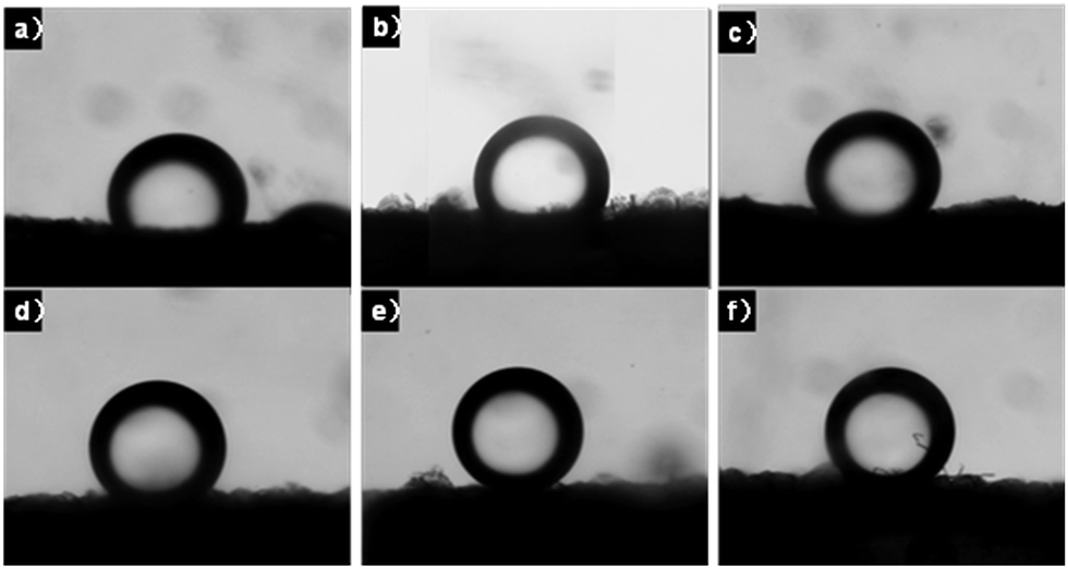
Fig. 3a–c show the oil contact angles (CA) on flat PAA, disordered MMT/PAA and ordered layer MMT/PAA film without porous structure underwater, respectively. These surfaces showed oleophobicity underwater with CAs of 113.9 ± 2.4°, 125.8 ± 3.6° and 118.4 ± 1.8°, respectively (Table 1). Fig. 3d–f show the oil CAs on PAA, disordered MMT/PAA and ordered layer MMT/PAA porous films underwater, respectively. Similarly, the porous surfaces showed oleophobicity or superoleophobicity with CAs of 138.4 ± 3.2°, 153.6 ± 4.2° and 141.6 ± 3.9°, respectively (Table 1). CAs of oil droplets on these flat surfaces and porous structure surfaces were larger than 90°. The results confirmed that these surfaces exhibited oleophobic or superoleophobic properties underwater. As compared to the flat films, the CAs increases of the porous films indicate that the oleophobicity of porous films increased as the pores are added. The increase of the oleophobicity underwater is mainly ascribed to the increase of the surface roughness, which results in the large CAs.
Table 1 Oil CAs of various samples underwater
| Sample type |
PAA (°) |
Disordered MMT/PAA (°) |
Ordered MMT/PAA (°) |
| Flat film |
113.9 ± 2.4 |
125.8 ± 3.6 |
118.4 ± 1.8 |
| Porous film |
138.4 ± 3.2 |
153.6 ± 4.2 |
141.6 ± 3.9 |
 |
| | Fig. 3 Oil CA photos on flat films and porous films underwater. (a) PAA flat film, (b) disordered MMT/PAA flat film, (c) ordered layer MMT/PAA flat film, (d) PAA porous film, (e) disordered MMT/PAA porous film, (f) ordered layer MMT/PAA porous film. Oil is 1,2-dichloroethane. | |
As to the PAA, disordered MMT/PAA and ordered layer MMT/PAA films with closed pore structure, the oleophobicity or superoleophobicity property is resultant from the water trapped in the pore, which can prevent the intrusion of oil into the pore. For a rough surface composed of solid and air, Cassie et al. proposed a model describing the contact angle in a water/air/solid system. In an oil/water/solid system, on the other hand, where the rough surface is composed of solid and water, the Cassie model is expressed as follows:1,28
where
f is the area fraction of solid,
r is the roughness factor,
θ is the CA of an oil droplet on a flat surface underwater, and
θ′ is the CA of an oil droplet on a rough surface underwater. In our study, taking 1,2-dichloroethane as an example, the contact angles
θ′ and
θ were respectively measured to be 138.4 ± 3.2°and 113.9 ± 2.4° when the oil drop was in contact with porous structure PAA surface and flat PAA surface, 153.6 ± 4.2° and 125.8 ± 3.6° for disordered MMT/PAA porous surface and disordered MMT/PAA flat surface, and 141.6 ± 3.9° and 118.4 ± 1.8° for ordered layer MMT/PAA porous surface and ordered layer MMT/PAA flat surface. The solid area fraction
f for all kinds of samples is calculated to be
ca. 0.44 according to SEM images. So the roughness factors (
r) of PAA, disordered MMT/PAA and ordered MMT/PAA porous film are 1.0, 1.3 and 1.1, respectively.
Oil adhesive behavior of the porous surfaces at different pHs
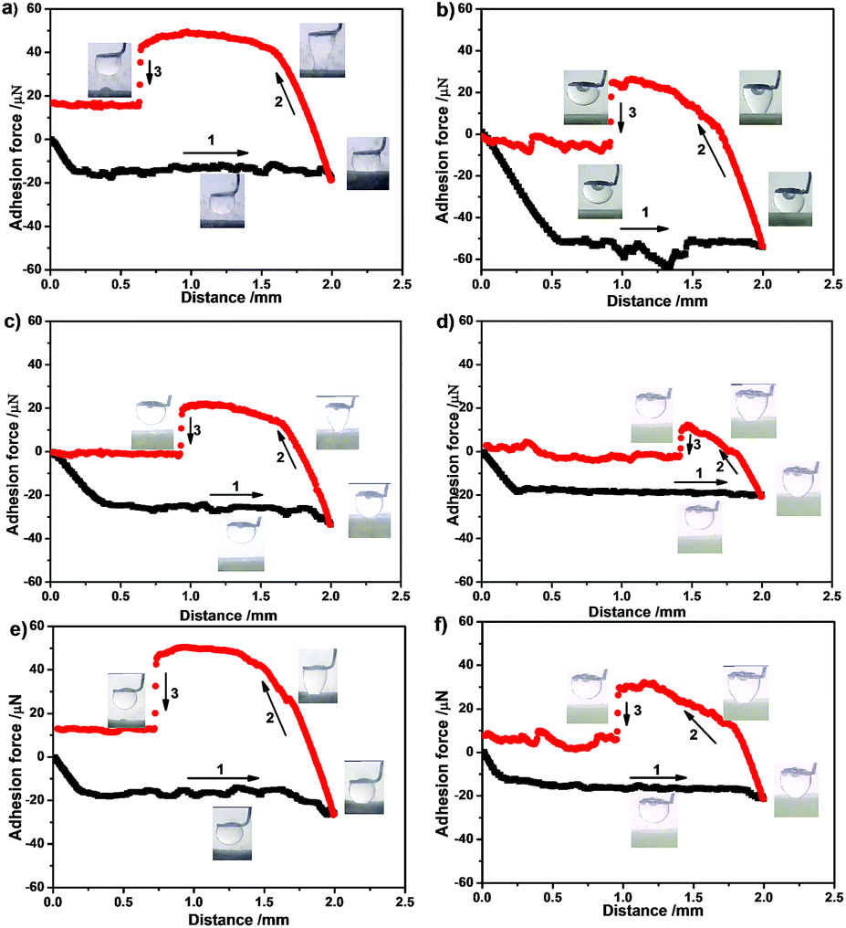
The adhesive force was defined as the force required to lift the oil droplet off the substrate and can be assessed by a highly sensitive micromechanical balance system. An optical microscope lens and a charge-coupled-device (CCD) camera system were used to record images during the experiment. The whole curve of the force versus the distance between the solid surface and the oil droplet is plotted in Fig. 4. The distance is the film movement length from a certain base (zero) position to the oil droplet. Fig. 4a and b are force–distance curves recorded before and after the oil droplet contacting with the PAA porous film underwater in acidic and basic solution, respectively. At first, the film was placed on the plate of the balance system underwater, and a 5 μl oil droplet was suspended on a metal ring. Then, the film was brought into contact with the oil droplet (process 1). The film was moved at a rate of 0.01 mm s−1. When the film left the oil droplet after contact, the balance force increased gradually and reached its maximum of 37.0 ± 2.9 μN in acidic solution and 32.5 ± 3.3 μN in basic solution at the end of process 2 (Table 2). Finally, the balance force decreased immediately when the film broke away from the oil droplet in process 3 to finish one cycle of the force measurement. This surface displayed large adhesive behavior both in acidic and in basic solution, which makes the oil droplet able to snap on the surface (Fig. 4a and b insets). Before the substrate was about to leave the oil drop, the shape of the oil drop first changed from spherical to elliptical and then changed back to spherical after the oil drop was displaced from the surface. These results show that a porous PAA surface shows high adhesion both in acidic solution and in basic solution. But the adhesion is larger in acidic solution than that in basic solution. This adhesion difference is caused by different hydrogen bonding interactions. At low pH, intramolecular hydrogen bonding of PAA is formed and results in high oil adhesion. At high pH, the oil droplets adhesion decreases due to the intermolecular hydrogen bonding between PAA and surrounding water.14
 |
| | Fig. 4 Force-distance curves recorded before and after the oil droplet is in contact with the surface underwater. The distance of x axis is the film movement length from a certain base (zero) position to the oil droplet. Process 1: the surface approaches the oil droplet. Process 2: the surface moves downward after being in contact with the oil droplet, and the adhesive force is increased with the increase distance between the film and the suspender. Process 3: the oil droplet moves away from the surface. Insets: photographs of the oil droplet shapes underwater taken at the corresponding stages during the measuring process. (a) PAA porous film in pH 2.2 solution, (b) PAA porous film in pH 11.2 solution, (c) disordered MMT/PAA porous film in pH 2.2 solution, (d) disordered MMT/PAA porous film in pH 11.2 solution. (e) Ordered layer MMT/PAA porous film in pH 2.2 solution, (f) ordered layer MMT/PAA porous film in pH 11.2 solution. | |
Table 2 Oil adhesion of various films in acid and basic solution
| Sample type |
PAA (μN) |
Disordered MMT/PAA (μN) |
Ordered MMT/PAA (μN) |
| pH 2.2 |
37.0 ± 2.9 |
21.6 ± 2.6 |
33.3 ± 2.4 |
| pH 11.2 |
32.5 ± 3.3 |
12.1 ± 1.6 |
24.1 ± 1.8 |
The same experiments were conducted to study the adhesion behavior of the disordered MMT/PAA porous films (Fig. 4c and d) and ordered layer MMT/PAA porous films (Fig. 4e and f). The disordered MMT/PAA porous films have its adhesion of 21.6 ± 2.6 μN in acidic solution and 12.1 ± 1.6 μN in basic solution (Table 2). This surface displayed small adhesive behavior in basic solution compared to that in acidic solution, which makes the oil droplet unable to snap on the surface (Fig. 4c and d insets). The ordered layer MMT/PAA porous films have its adhesion of 33.3 ± 2.4 μN in acidic solution and 24.1 ± 1.8 μN in basic solution. This surface also displayed large adhesive behavior in acidic solution compared to that in basic solution, which makes the oil droplet able to snap on the surface in acidic solution (Fig. 4e insets). It has the similar discipline compared to the porous PAA film in solutions at different pH values. The above data showed that the adhesions of all the samples in acidic solution are larger than that in basic solution. But for disordered MMT/PAA porous film, the adhesion is relatively small both in acidic solution and in basic solution.
Mechanism affecting the adhesive force
In general, the adhesion of the surface can be governed by both the chemical composition and the geometrical microstructures.29 From horizontal comparison (Table 2), it can be seen that the adhesion of all kinds of samples is larger in acid solution than that in basic solution. At low pH, intramolecular hydrogen bonding of PAA is formed and results in high oil adhesion. As for high pH, the intermolecular hydrogen bonding between PAA and surrounding water is formed, which decreases the oil adhesion.14 But from vertical comparison, we can see that the adhesion decreases with the MMT addition to the film both in acid solution and in basic solution. But the disordered MMT/PAA porous film has the smallest adhesion both in acid solution and in basic solution. This unusual adhesion phenomenon is caused by the different nanocomposite internal structure. As for the disordered MMT/PAA and ordered layer MMT/PAA porous films, the adhesion decreases are mainly caused by decreasing the continuity of TCL30,31 (Fig. 5), which is caused by the increase of the surface roughness. Therefore, the surface adhesive force of disordered MMT/PAA porous surface would be the smallest because it has the largest surface roughness (r = 1.3). Compared with porous PAA film, the adhesion decreases of ordered layer MMT/PAA porous film are mainly caused by the different chemical composition. The ordered layer MMT/PAA porous film has low surface energy and low adhesion compared with that of PAA porous film though these two kinds of films have similar roughness (1.0 and 1.1).
 |
| | Fig. 5 Effect of internal structure change in the pore wall on the oil adhesive behavior underwater. (a) PAA porous surface is the Cassie states. TCL is relative continuous. (b) TCL of disordered MM/PAA porous surface becomes discontinuous because the composite film roughness increased by the disordered MMT platelets. (c) TCL of ordered layer MM/PAA porous surface becomes continuous because the composite film roughness decreased by the ordered layer MMT platelets in the wall. | |
Conclusions
A porous structure polymer surface with controllable oil adhesion underwater was achieved. Characterization of the adhesion indicates that the disordered MMT/PAA porous films can serve as low adhesive surface in both acidic and basic aqueous phases. Besides, the adhesion can be controlled by changing MMT arrangement in the pore wall and solution pHs. The switchable oil adhesion is attributed to regulating TCL continuity induced by MMT arrangement. The unique adhesive phenomenon of porous structure will be suitable for the application in controlling liquid collection and transportation underwater. These findings will help us to design novel adhesive materials by adjusting microstructure in the film, which can be used for the construction of the future generation of microdevices and have potential applications in liquid transportation, biochemical separation, in situ detection, microfluid systems, and other areas. This study also helps better understand the adhesion of solid surfaces underwater, and hence may contribute to underwater bionic applications in future.
Acknowledgements
This work was supported by the National Basic Research Program of China (2014CB931802 and 2013CB834705), the Fundamental Research Funds for the Central Universities (YWF-15-HHXY-021) and China Scholarship Council.
Notes and references
- M. J. Liu, S. T. Wang, Z. X. Wei, Y. L. Song and L. Jiang, Adv. Mater., 2009, 21, 665–669 CrossRef CAS.
- M. J. Liu, Y. M. Zheng, J. Zhai and L. Jiang, Acc. Chem. Res., 2010, 43, 368–377 CrossRef CAS PubMed.
- M. Nosonovsky and B. Bhushan, Philos. Trans. R. Soc., A, 2009, 367, 1511–1539 CrossRef CAS PubMed.
- Y. C. Jung and B. Bhushan, Langmuir, 2009, 25, 14165–14173 CrossRef CAS PubMed.
- L. Chen, M. J. Liu, H. Bai, P. P. Chen, F. Xia, D. Han and L. Jiang, J. Am. Chem. Soc., 2009, 131, 10467–10472 CrossRef CAS PubMed.
- Y. Huang, M. J. Liu, J. X. Wang, J. M. Zhou, L. B. Wang, Y. L. Song and L. Jiang, Adv. Funct. Mater., 2011, 21, 4436–4441 CrossRef CAS.
- L. P. Xu, J. Zhao, B. Su, X. L. Liu, J. T. Peng, Y. B. Liu, H. L. Liu, G. Yang, L. Jiang, Y. Q. Wen, X. J. Zhang and S. T. Wang, Adv. Mater., 2013, 25, 606–611 CrossRef CAS PubMed.
- X. L. Liu, J. Zhou, Z. X. Xue, J. Gao, J. X. Meng, S. T. Wang and L. Jiang, Adv. Mater., 2012, 24, 3401–3405 CrossRef CAS PubMed.
- Y. Cai, Q. H. Lu, X. L. Guo, S. T. Wang, J. L. Qiao and L. Jiang, Adv. Mater., 2015, 27, 4162–4168 CrossRef CAS PubMed.
- L. P. Xu, X. W. Wu, J. X. Meng, J. T. Peng, Y. Q. Wen, X. J. Zhang and S. T. Wang, Chem. Commun., 2013, 49, 8752–8754 RSC.
- L. P. Xu, J. T. Peng, Y. B. Liu, Y. Q. Wen, X. J. Zhang, L. Jiang and S. T. Wang, ACS Nano, 2013, 7, 5077–5083 CrossRef CAS PubMed.
- J. Y. Huang, Y. K. Lai, L. N. Wang, S. H. Li, M. Z. Ge, K. Q. Zhang, H. Fuchs and L. F. Chi, J. Mater. Chem. A, 2014, 2, 18531–18538 CAS.
- D. L. Tian, Z. Y. Guo, Y. L. Wang, W. X. Li, X. F. Zhang, J. Zhai and L. Jiang, Adv. Funct. Mater., 2014, 24, 536–542 CrossRef CAS.
- Q. F. Cheng, M. Z. Li, F. Yang, M. J. Liu, L. Li, S. T. Wang and L. Jiang, Soft Matter, 2012, 8, 6740–6743 RSC.
- L. Tie, Z. G. Guo and W. M. Liu, ACS Appl. Mater. Interfaces, 2015, 7, 10641–10649 CAS.
- L. Chen, M. J. Liu, L. Lin, T. Zhang, J. Ma, Y. L. Song and L. Jiang, Soft Matter, 2010, 6, 2708–2712 RSC.
- C. M. Ding, Y. Zhu, M. J. Liu, L. Feng, M. X. Wan and L. Jiang, Soft Matter, 2012, 8, 9064–9068 RSC.
- T. Q. Guo, M. C. Li, L. P. Heng and L. Jiang, RSC Adv., 2015, 5, 62078–62083 RSC.
- M. S. Xue, W. F. Wang, F. J. Wang, J. F. Ou and W. Li, Surf. Coat. Technol., 2014, 258, 200–205 CrossRef CAS.
- J. L. Yong, F. Chen, Q. Yang, D. S. Zhang, U. Farooq, G. Q. Du and X. Hou, J. Mater. Chem. A, 2014, 2, 8790–8795 CAS.
- M. C. Li, B. Wang, L. P. Heng and L. Jiang, Adv. Mater. Interfaces, 2014, 1400298 Search PubMed.
- L. P. Heng, X. F. Meng, B. Wang and L. Jiang, Langmuir, 2013, 29, 9491–9498 CrossRef CAS PubMed.
- V. Vertlib, M. Dietiker, M. Ploetze, L. Yezek, R. Spolenak and A. M. Puzrin, J. Mater. Res., 2008, 23, 1026–1035 CrossRef CAS.
- D. A. Dikin, S. Stankovich, E. J. Zimney, R. D. Piner, G. H. B. Dommett, G. Evmenenko, S. T. Nguyen and R. S. Ruoff, Nature, 2007, 448, 457–460 CrossRef CAS PubMed.
- X. Wang, H. Bai, Z. Yao, A. Liu and G. Shi, J. Mater. Chem., 2010, 20, 9032–9036 RSC.
- J. F. Wang, L. Lin, Q. F. Cheng and L. Jiang, Angew. Chem., Int. Ed., 2012, 51, 4676–4680 CrossRef CAS PubMed.
- K. Haraguchi, H. J. Li, K. Matsuda, T. Takehisa and E. Elliott, Macromolecules, 2005, 38, 3482 CrossRef CAS.
- A. B. D. Cassie and S. Baxter, Trans. Faraday Soc., 1944, 40, 546–551 RSC.
- W. Lee, B. G. Park, D. H. Kim, D. J. Ahn, Y. Park, S. H. Lee and K. B. Lee, Langmuir, 2010, 26, 8233–8238 CrossRef PubMed.
- L. C. Gao and T. J. McCarthy, Langmuir, 2007, 23, 3762–3765 CrossRef CAS PubMed.
- W. Chen, A. Y. Fadeev, M. C. Hsieh, D. Öner, J. Youngblood and T. J. McCarthy, Langmuir, 1999, 15, 3395–3399 CrossRef CAS.
Footnote |
| † Electronic supplementary information (ESI) available: SEM image of hexagonal silicon pillar templates, AFM images of clay platelets on silicon substrate, X-ray diffraction profiles for dried materials. See DOI: 10.1039/c5ra20280a |
|
| This journal is © The Royal Society of Chemistry 2015 |
Click here to see how this site uses Cookies. View our privacy policy here.