Leaf-inspired artificial microvascular networks (LIAMN) for three-dimensional cell culture

Rong Fana, Yihang Sunb and Jiandi Wan*a
aDepartment of Microsystems Engineering, Rochester Institute of Technology, NY14623, USA. E-mail: jdween@rit.edu
bDepartment of Imaging Science, Rochester Institute of Technology, NY14623, USA

Received 30th September 2015 , Accepted 19th October 2015

First published on 19th October 2015


Abstract

Construction of vascular architecture capable of distributing oxygen and nutrients is critically important for 3D cell culture. Here, we demonstrate leaf-inspired artificial microvascular networks (LIAMN) that serve as an effective perfusion system for 3D cell culture in hydrogel constructs. Because cell-containing hydrogel constructs with desired thickness can be constructed using embedded LIAMN layers, our strategy paves a new avenue to engineering effective vascular transport system for 3D cell culture and the development of functional artificial organs.
Effective vascularization in engineered tissues is critical to the development of living organs and remains one of the highest priorities in tissue engineering.1–4 Without a vascular network, for example, the maximal thickness of an engineered tissue is approximately 150–200 μm due to the limited oxygen diffusion.5 As a result, large three-dimensional (3D) engineered tissue constructs quickly develop necrotic regions.6 Thus, an effective transport system including both large vascular vessels and microvascular networks is required to sustain the biomimetic functions of thick, complex tissue constructs. To date, tissue engineered large and small blood vessels have been demonstrated by using porous scaffolds7 and cell sheet technology.8 However, controlled formation of complex, hierarchical microvascular networks, such as the degree of branching, capillary density, and connecting microvascular networks with large vascular vessels is challenging.

Recent advances in micro-fabrication technology have enabled the generation of microvascular networks in tissue constructs. Microfluidic-based systems, for example, have been developed to control the fabrication of vascularized patterns in a variety of bio-substrates where endothelial cells can be seeded and form monolayers.9 In particular, the development of biodegradable microfluidics and 3D vascularized microfluidic scaffolds10,11 highlights the potentially implantable 3D microfluidic tissue constructs. 3D bioprinting, on the other hand, is essentially a microfluidic technology1 and has been emerged rapidly as an effective bottom-up approach to fabricate vascularized 3D tissue constructs.12,13 A rapid prototyping bioprinting method for scaffold-free small diameter vascular reconstruction has been demonstrated for the fabrication of single- and double-layered small diameter vascular tubes (OD ranging from 0.9 to 2.5 mm).14 Vascularized cell-laden tissue constructs have also been fabricated by 3D printing a fugitive ink (Pluronic F127) in cell-containing gelatin methacrylate hydrogels.15 Furthermore, 3D printed filament networks of carbohydrate glass16 and agarose template fibers17 have been used as cytocompatible sacrificial templates to generate vascular networks in engineered tissues. Improved mass transport, cell viability and differentiation within the cell-laden tissue constructs have been observed. Formations of microvascular architectures using methods such as direct writing18 and electrical discharge19,20 have also been demonstrated. In addition, studies using micropatterning and microfluidics have been investigated to fabricate vascularized hydrogel for 3D cell culture, such as grid networks and hollow hydrogel fibers.16,21,22 The majority of the studies, however, failed to demonstrate the rationale of the construction of hierarchical networks, e.g., how the diameter of the channel and the degree of branching change with hierarchical levels, in order to maintain the maximum flow efficiency in the network. This is particularly of interest when maximum flow efficiency for material delivery at a given input pressure or flow rate is required or becomes a concern.

Evolutionary innovations in the venation patterns of leaves, on the other hand, allow the effective transport of water, nutrients and carbon throughout the entire leaf,23–25 and thus might provide an alternative approach to overcome the supplying difficulties in 3D cell culture and enable an effective distribution of nutrient and oxygen. Indeed, hydraulic analysis of water flow through leaves of sugar maple (Acer saccharum) and red oak (Quercus rubra) has shown that the hydraulic architecture of leaves minimizes construction costs relative to hydraulic capacity.26 Venation patterns of leaves also have an optimized vein density.27 Furthermore, studies of the isotopic composition of leaf water have demonstrated the presence of hydraulic capacitance in the ground tissues of vein ribs and a lateral exchange of water from veins,28 suggesting that major veins serve as high-capacity supply lines to minor vein system. All these characteristics of venation patterns of leaves including minimized construction costs, optimized vein density, and hierarchical connection of microvascular vein with large vessels are ideal features of microvascular networks for 3D cell culture.29 Furthermore, the presence of the diversification of low-order vein architecture and the commonness of reticulate, hierarchical leaf venation provides tolerances to hydraulic disruption through wounding,30 highlighting the advantages of leaf vascular architecture in hydraulic (or nutrient) transport. Thus, over 400 million years evolution, the hydraulic system of leaves has been evolved as such a transport system that no portion of the leaf is under-supplied, and therefore, is likely be able to act as an effective microvascular perfusion system for 3D cell culture.

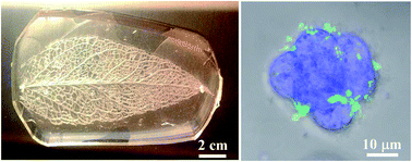
Here, we propose a concept of leaf-inspired artificial microvascular networks (LIAMN) and demonstrate that LIAMN is applicable and advantageous for 3D cell culture. This is shown by developing both leaf-mimicking (Fig. 1a) and leaf-inspired (Fig. 1b) microfluidic perfusion systems to support the growth of HCT116 colon cancer cells in a 3D hydrogel matrix. In particular, by assembling three layers of LIAMN, we show that cells cultured in agarose hydrogel matrix can receive supplying medium from the embedded vascular system and keep growing for at least 14 days. Because the thickness of the hydrogel matrix depends on the number of assembled layers of LIAMN, there is no limitation to achieve much thicker hydrogel matrix for 3D cell culture. Although 2D leaf-mimicking network has been developed previously for cell culture,31 the thickness of the leaf is much smaller than that of 3D hydrogel construct, and thus 2D leaf-mimicking device is marginally effective to deliver culture medium in thick hydrogel construct. In addition, comparing to the majority approaches of 3D cell culture where highly porous scaffolds (normally with less mechanical stiffness) have to be used to ensure the diffusion of nutrients to embedded cells,32 LIAMN not only maintains a high cell viability in less porous agarose gel,33 but also exhibits desired mechanical strength to support hydrogel constructs, which is critical for the construction of artificial organs.34 Last, the approach we developed here combines established models for the development of LIAMN, which provides novel and much needed strategies for the construction of vascular networks for 3D cell culture. Our approach thus opens a new avenue that enables the efficacious engineering of vascular networks in thick hydrogel constructs and provides a novel conceptual and experimental framework for vascular tissue engineering.


image file: c5ra20265e-f1.tif
Fig. 1 Schematics of the fabrication of leaf-mimicking and leaf-inspired microfluidic devices for 3D cell culture. (A) Fabrication process of a leaf-mimicking microfluidic device. A leaf skeleton with pinnate venation (Hevea brasiliensis) is used as the master and molded with cell-containing agarose hydrogel. (B) Fabrication of multilayer leaf-inspired microfluidic device.

To develop leaf-mimicking microfluidic devices, we use the skeleton of leaves with pinnate venation, e.g., rubber tree leaves (Hevea brasiliensis), as the template. Pinnate venation has a main vein that extends from the bottom to the tip of the leaf, from which small veins are branching off. The main vein can serve as the high-capacity supply lines for fast, long-distance water transport,35 whereas the hierarchical structure derived along the central axis into higher order branches (network area) can carry out local dispersion. In addition, pinnate-veined leaves (with an elliptic shape) have a high density of minor veins comparing to parallel- or palmate-veined leaves,36 and thus are expected to have a better hydraulic conductance.37 We then fabricated PDMS-based leaf-mimicking microfluidic devices and studied the hydraulic conductance in such devices (Fig. S1). The results show that, given a relatively high input pressure, high water coverage can be obtained when the outlets of the device are located at the network area replicated from the original leaf. Because we are interested in the development of perfusion systems for 3D cell culture where a high coverage of culture medium in the device is desired, the outlets of the devices in the following studies are always located at the network area.

We next fabricated the leaf-mimicking microfluidic devices using cell-containing agarose and examined the growth of HCT116 colon cancer cells in such devices (Fig. 2a). Briefly, agarose (2 wt%) was mixed with HCT116 cells in a DMEM culture medium (1 × 10⁸ ml−1) and used as the hydrogel matrix to fabricate the agarose-based leaf-mimicking microfluidic device. After the device was fabricated, it was then immersed in a 2 ml DMEM culture medium and cultured for 3 days. In addition, a continuous supply of culture medium through the leaf-mimicking microfluidic channel was applied. We then examined the viability of cells within 200 μm to the channel and found that after 3 days, cells located at the network area, near the 1st order branches and main vein had a viability of 95%, 93%, and 83%, respectively (Fig. 2b). In contrast, the overall viability of cells cultured in agarose constructs with simple straight channels (within 200 μm to the channel) dropped to 60%, whereas the viability of cells located beyond 200 μm from the channel decreased to 35%. Because diffusion-based medium delivery in both devices is approximately the same, the enhanced cell viability in the leaf-mimicking devices suggests that a continuous supply of culture medium and oxygen29 through the leaf-mimicking microfluidic channel is essential to maintain the cell homeostasis in hydrogel. In addition, the high viability of cells located at different locations of the leaf-mimicking devices implies a relatively homogeneous distribution of culture medium in the hydrogel construct, and thus shows the advantages of leaf-based microvascular network for 3D cell culture. It should be noted, however, that because the leaf used here has approximately a two-dimensional structure, e.g., the thickness of the leaf is much smaller than that of its size, leaf-mimicking microfluidic devices are limited to deliver culture medium in thick hydrogel constructs.


image file: c5ra20265e-f2.tif
Fig. 2 HCT116 colon cancer cells in agarose-based leaf-mimicking microfluidic devices. (A) Image of cultured HCT116 cells in the network area of the leaf-mimicking agarose microfluidic devices. Scale bar: 100 μm. (B) Viability of HCT116 cells cultured near the main vein, the 1st order branch, and the network area in 3 days. Agarose matrix with simple straight channels is served as control. Viability of cells located within 200 μm to the channel and beyond is measured.

In order to improve the feasibility and controllability of leaf-based microvascular structures for 3D cell culture, we further develop a leaf-inspired artificial microvascular networks (LIAMN). We combine the Murray's law, area preserving assumption, volume filling assumption, and L-system to determine the key parameters that control the patterns of the leaf-inspired microfluidic devices. Specifically, the degree of branching of channels is determined by L-system, which has been primarily developed for description of the branching model of plants.38 L-system translates generated strings into the derivation of alphabet symbols for illustrating the relationships between plant branches, and thus allows the generation of complex models by using short numbers as input parameters. For example, a typical approach to generate branches in L-system is (A → AB) and (B → A). (A → AB) means that the parent branch A bifurcates into daughter branches A and B leading to the 1th order of the level increase. (B → A) indicates that daughter branch B returns to branch A for further bifurcation, without addition of the order level. By repeating the process, complex branching structures with high orders of levels can be generated.

The radius of branches at different levels, on the other hand, is determined by the Murray's law and area preserving assumption. Most of branching vasculatures including leaf venations and mammalian circulatory and respiratory systems obey the Murray's law, because maximum flow efficiency is found to occur when the law is obeyed.39,40 When flow is laminar and the volumetric flow rate is conserved, Murray's law equalizes the sum of the radii cubed between the parent and bifurcated daughter branches, image file: c5ra20265e-t1.tif, where rdaughter is the radius of daughter branches, and rparent is the radius of parent branches. However, large branches with diameter greater than 1 mm follow closely to the area preserving assumption,41,42 which states that the sum of the square of the radii of the daughter branches (rdaughter) equals the square of the radius of the parent vessels (rparent), image file: c5ra20265e-t2.tif. Area preserving assumption has also been verified by studying the transport efficiency in larger hydraulic architecture like xylem, canopy area, and branches derived from trunk. Therefore, in our study, the area preserving assumption is used when the branch diameter is larger than 1 mm, whereas the Murray's law is applied only for small branches. Last, to determine the length of each branches, we utilize the volume filling assumption, which states that the product of the number of daughter branches and the cube of their length equals the product of their parent branches, Nk × Lk3 = Nk+1 × Lk+13, where Nk and Nk+1 is the number of branches at level k and level k + 1, while the Lk and Lk+1 are their branch length respectively. Assuming the network is composed of identical tubes of equal length, volume filling assumption ensures each of the branch would receive equal supply from the parent branch, and meanwhile maintain a constant flow.43 This assumption has been found well-fit in trees and shrubs, particularly angiosperms and conifers.43,44

Based on the principles discussed above, we have constructed a leaf-inspired microfluidic network with five levels of branches (n = 5). The radius (d) and length (l) of each branch (channel) at specific levels are calculated accordingly (Fig. 3a and Table S1). In addition, two leaf-inspired microfluidic networks are combined together by connecting channels at the 5th order of the network and form a single microfluidic perfusion system, in which two main veins from each network serve as the inlet and outlet respectively (Fig. 3a). A single layer of cell-containing agarose replica with thickness of 300 ± 52 μm is then developed using the leaf-inspired microfluidic perfusion system as template. By assembling three pieces of such agarose replica, we are able to construct 3D multi-layer agarose constructs with a thickness about 1 mm (Fig. 3b). Bright field image of the cross-sectional area of the constructs shows the microfluidic channels at each layer (Fig. 3c). Although some of the channels are partially collapsed (presumably due to the cutting process), aqueous solution such as fluorescein sodium salt solution can be delivered throughout the whole construct (Fig. 3b). Note that inlet and outlets holes were punched throughout all the layers of the agarose device. The tubing was inserted to the top layer such that fluids can flow down vertically to all the inlets in different layers and distribute laterally into the vascular networks at each layer.


image file: c5ra20265e-f3.tif
Fig. 3 Leaf-inspired microfluidics for 3D cell culture. (A) Schematic of the design of leaf-inspired microfluidics. The order of branching level (n), the diameter (d) and the length of branches (l) at each branching level are determined by combining L-system, Murray's law, area preserving assumption, and volume filling assumption. Unit: mm. (B) Assembly of a three-layer agarose microfluidic device for 3D cell culture. Note that fluorescein sodium salt solution is injected into the device to show the designed pattern. Scale bar: 2 mm. (C) Image of the cross-sectional view of the assembled three-layer agarose microfluidic device. Channels in different layers are highlighted using white dot lines. Scale bar: 200 μm. (D) 3D construction of confocal images of HCT116 cells in the three-layer agarose microfluidic device. Cells are stained by nucleus-blue fluorescent dye. Positions of channels are marked by white dot lines. Scale bar: 200 μm. (E) Viability of HCT 116 cells cultured in the three-layer agarose matrix.

Indeed, when fluorescein sodium salt solution is injected into the 3D construct, we find that not only does the dye solution flow through the vascular structure laterally, diffusion between agarose layers is also observed, e.g., the appearance of blurred fluorescence between layers (Fig. 3b). This phenomenon has not been observed in PDMS devices where diffusion of fluorescein into PDMS is negligible (Fig. S2). Because cells encapsulated in the middle of the agarose layer is approximately 150 μm apart from the perfusion channel located at the upper and lower agarose layers, cells can receive oxygen and nutrient from the perfusion channel by diffusion. In fact, cells cultured in the entire 3D agarose construct are located within the distance of 13–89 μm from the nearby channels (Fig. 3d) and will receive supplies by either lateral flow or vertical diffusion. When HCT116 cells are encapsulated in each agarose layer (Fig. 3d) and cultured for 24 hours in the stacked agarose constructs, for example, the viability of cells is 72%, 80% and 85% for top, middle, and bottom layer, respectively (Fig. 3e), implying that the perfusion system is able to effectively deliver the culture medium to cells at each layer. The deviation of cell viability from each layer may arise from the introduction of culture medium, because there are pressure differences between the inlet and different layers, which may result in different medium distributing efficiency between layers. Note that the cell viability is measured in the area of 3rd–5th order branches but throughout the entire hydrogel construct.

To examine the feasibility of the developed LIAMN for long-term cell culture, we have monitored the growth of cells inside the 3D agarose constructs for 14 days. Fig. 4a shows the distribution of cells in the 3D agarose constructs at the beginning of the culture (day 1). After three days, most of the cells start to divide for proliferation, which can be observed by the increased fluorescent intensity of living cells on day 3 and 9 (Fig. 4b and c). Notably, formation of cell spheroids has been observed at day 9 (Fig. 4c). Fig. 4d shows the cell spheroids stained by actin-green and nucleus-blue. Evidently, nucleus forms cluster whereas actin are mostly surrounding at the edge of the spheroid. At day 14, however, dead cells start to appear (Fig. S3), presumably due to the nature of the agarose matrix.33 Nevertheless, the developed LIAMN system has realized the superiority of microfluidics for nutrient supply and removal of metabolic waste through the embedding vascular systems and provides a new approach to obtain long-term spheroid culture.


image file: c5ra20265e-f4.tif
Fig. 4 Growth of HCT116 cells in the developed three-layer leaf-inspired agarose matrix. 3D construction of confocal images of HCT116 cells stained with cell Live/Dead assay at day 1 (A), 3 (B), and 9 (C) of culture. Scale bar: 200 μm. Inset: merged bright-field and fluorescent images of cells at the single cell level. Scale bar: 5 μm. (D) Merged bright-field and fluorescent image of cell spheroids stained with actin-green and nucleus-blue fluorescent dye. Scale bar: 100 μm. Inset: fluorescent image of a single spheroid. Scale bar: 10 μm.

Conclusions

In summary, we have introduced microfluidic approaches to explore direct replication of leaf venation and LIAMN for the construction of complex and hierarchical microvascular networks for 3D cell culture. Our approach begins with leaf-mimicking microfluidic perfusion system fabricated via direct replication of leaf venation structures and shows that such perfusion system can maintain high cell viability for short-term 3D cell culture. We subsequently incorporate the framework of branching models to construct the leaf-inspired microfluidic perfusion systems that support cell growth in 3D hydrogel constructs for at least two weeks. The developed LIAMN thus may open new avenues that enable the efficacious engineering of vascular networks in thick tissue constructs. Furthermore, the current approach also provides a strategy in which an algorithm can be developed to tune geometric factors such that cell growth, nutrient delivery and biological processes can be regulated in a dynamic and time dependent manner in 3D.

Acknowledgements

The authors gratefully acknowledge the support from the Rochester Institute of Technology. We also thank Daniel Phillips for helpful discussion on L-system, and Hyla Sweet and Evan Darling for help on confocal microscopy.

Notes and references

  1. R. P. Visconti, V. Kasyanov, C. Gentile, J. Zhang, R. R. Markwald and V. Mironov, Expert Opin. Biol. Ther., 2010, 10, 409 CrossRef PubMed.
  2. R. Y. Kannan, H. J. Salacinski, K. Sales, P. Butler and A. M. Seifalian, Biomaterials, 2005, 26, 1857 CrossRef CAS PubMed.
  3. F. A. Auger, L. Gibot and D. Lacroix, Annu. Rev. Biomed. Eng., 2013, 15, 177 CrossRef CAS PubMed.
  4. E. C. Novosel, C. Kleinhans and P. J. Kluger, Adv. Drug Delivery Rev., 2011, 63, 300 CrossRef CAS PubMed.
  5. J. Folkman and M. Hochberg, J. Exp. Med., 1973, 138, 745 CrossRef CAS.
  6. K. Alessandri, B. R. Sarangi, V. V. Gurchenkov, B. Sinha, T. R. Kiessling, L. Fetler, F. Rico, S. Scheuring, C. Lamaze, A. Simon, S. Geraldo, D. Vignjevic, H. Domejean, L. Rolland, A. Funfak, J. Bibette, N. Bremond and P. Nassoy, Proc. Natl. Acad. Sci. U. S. A., 2013, 110, 14843 CrossRef CAS PubMed.
  7. S. L. Dahl, A. P. Kypson, J. H. Lawson, J. L. Blum, J. T. Strader, Y. Li, R. J. Manson, W. E. Tente, L. Dibernardo, M. T. Hensley, R. Carter, T. P. Williams, H. L. Prichard, M. S. Dey, K. G. Begelman and L. E. Niklason, Sci. Transl. Med., 2011, 3, 68ra69 Search PubMed.
  8. R. Gauvin, T. Ahsan, D. Larouche, P. Levesque, J. Dube, F. A. Auger, R. M. Nerem and L. Germain, Tissue Eng., Part A, 2010, 16, 1737 CrossRef CAS PubMed.
  9. Y. Du, D. Cropek, M. R. K. Mofrad, E. J. Weinberg, A. Khademhosseini and J. T. Borenstein, in Microfluidics for Biological Applications, ed. W. C. Tian and E. Finehout, Springer, New York, 2008, Ch. 7 Search PubMed.
  10. C. J. Bettinger, E. J. Weinberg, K. M. Kulig, J. P. Vacanti, J. T. Wang, J. T. Borenstein and R. Langer, Adv. Mater., 2006, 18, 165 CrossRef CAS PubMed.
  11. J. T. Borenstein, E. J. Weinberg, B. K. Orrick, C. Sundback, M. R. Kaazempur-Mofrad and J. P. Vacanti, Tissue Eng., 2007, 13, 1837 CrossRef CAS PubMed.
  12. V. Mironov, R. P. Visconti, V. Kasyanov, G. Forgacs, C. J. Drake and R. R. Markwald, Biomaterials, 2009, 30, 2164 CrossRef CAS PubMed.
  13. B. Guillotin and F. Guillemot, Trends Biotechnol., 2011, 29, 183 CrossRef CAS PubMed.
  14. C. Norotte, F. S. Marga, L. E. Niklason and G. Forgacs, Biomaterials, 2009, 30, 5910 CrossRef CAS PubMed.
  15. D. B. Kolesky, R. L. Truby, A. S. Gladman, T. A. Busbee, K. A. Homan and J. A. Lewis, Adv. Mater., 2014, 26, 3124 CrossRef CAS PubMed.
  16. J. S. Miller, K. R. Stevens, M. T. Yang, B. M. Baker, D. H. Nguyen, D. M. Cohen, E. Toro, A. A. Chen, P. A. Galie, X. Yu, R. Chaturvedi, S. N. Bhatia and C. S. Chen, Nat. Mater., 2012, 9, 768 CrossRef PubMed.
  17. L. M. Bellan, S. P. Singh, P. W. Henderson, T. J. Porri, H. G. Craighead and J. A. Spector, Soft Matter, 2009, 5, 1354 RSC.
  18. W. Wu, A. DeConinck and J. A. Lewis, Adv. Mater., 2011, 24, H178 CrossRef PubMed.
  19. J. H. Huang, J. Kim, N. Agrawal, A. P. Sudarsan, J. E. Maxim, A. Jayaraman and V. M. Ugaz, Adv. Mater., 2009, 21, 3567 CrossRef CAS PubMed.
  20. J. H. Huang, J. Kim, Y. Ding, A. Jayaraman and V. M. Ugaz, PLoS One, 2013, 8, e73188 CAS.
  21. N. Annabi, J. W. Nichol, X. Zhong, C. Ji, S. Koshy, A. Khademhosseini and F. Dehghani, Tissue Eng., Part B, 2010, 16, 371 CrossRef CAS PubMed.
  22. M. F. Leong, J. K. C. Toh, C. Du, K. Narayanan, H. F. Lu, T. C. Lim, A. C. A. Wan and J. Y. Ying, Nat. Commun., 2013, 4, 2353 CrossRef PubMed.
  23. C. K. Boyce, Paleobiology, 2005, 31, 117 CrossRef.
  24. J. S. Boyer, Annu. Rev. Plant Physiol., 1985, 36, 473 CrossRef.
  25. L. Sack and N. M. Holbrook, Annu. Rev. Plant Biol., 2006, 57, 361 CrossRef CAS PubMed.
  26. L. Sack, C. M. Streeter and N. M. Holbrook, Plant Physiol., 2004, 134, 1824 CrossRef CAS PubMed.
  27. X. Noblin, L. Mahadevan, I. A. Coomaraswamy, D. A. Weitz, N. M. Holbrook and M. A. Zwieniecki, Proc. Natl. Acad. Sci. U. S. A., 2008, 105, 9140 CrossRef CAS PubMed.
  28. K. S. Gan, S. C. Wong, J. W. H. Yong and G. D. Farquhar, Plant Physiol., 2002, 130, 1008 CrossRef CAS PubMed.
  29. T. Y. Kang, J. M. Hong, J. W. Jung, J. J. Yoo and D. W. Cho, Langmuir, 2013, 29, 701 CrossRef CAS PubMed.
  30. L. Sack, E. M. Dietrich, C. M. Streeter, D. Sanchez-Gomez and N. M. Holbrook, Proc. Natl. Acad. Sci. U. S. A., 2008, 105, 1567 CrossRef CAS PubMed.
  31. J. He, M. Mao, Y. Liu, J. Shao, Z. Jin and D. Li, Adv. Healthcare Mater., 2013, 2, 1108 CrossRef CAS PubMed.
  32. J. W. Haycock, in Methods in Molecular Biology, ed. J. M. Walker, Springer, 2011, Vol. 695, Ch. 1, pp. 1–15 Search PubMed.
  33. S. M. O'Connor, D. A. Stenger, K. M. Shaffer and W. Ma, Neurosci. Lett., 2001, 304, 189 CrossRef.
  34. A. Atala, F. K. Kasper and A. G. Mikos, Sci. Transl. Med., 2012, 4, 160rv12 Search PubMed.
  35. A. Roth-Nebelsick, D. Uhl, V. Mosbrugger and H. Kerp, Ann. Bot., 2001, 87, 553 CrossRef.
  36. U. Niinemets, A. Portsmuth and M. Tobias, Funct. Ecol., 2007, 21, 28 CrossRef PubMed.
  37. A. D. McKown, H. Cochard and L. Sack, Am. Nat., 2010, 175, 447 CrossRef PubMed.
  38. P. Prusinkiewicz, J. Hanan and R. Mech, in Lecture Notes in Computer Science, ed. M. Nagl, A. Schurr and M. Munch, Springer, Netherlands, 1999, Vol. 1779, pp. 395–410 Search PubMed.
  39. T. F. Sherman, J. Gen. Physiol., 1981, 78, 431 CrossRef CAS.
  40. W. Wu, C. J. Hansen, A. M. Aragon, P. H. Geubelle, S. R. White and J. A. Lewis, Soft Matter, 2010, 6, 739 RSC.
  41. Y. Huo and G. S. Kassab, J. R. Soc., Interface, 2012, 9, 190 CrossRef PubMed.
  42. C. A. Price, S. J. C. Knox and T. J. Brodribb, PLoS One, 2013, 8, e85420 Search PubMed.
  43. G. B. West, J. H. Brown and B. J. Enquist, Nature, 1999, 400, 664 CrossRef CAS.
  44. C. A. Price and B. J. Enquist, Funct. Ecol., 2006, 20, 11 CrossRef PubMed.

Footnote

Electronic supplementary information (ESI) available: Cell maintenance, device fabrication, hydraulic efficiency test, calculated parameters for leaf-inspired branching system. See DOI: 10.1039/c5ra20265e

This journal is © The Royal Society of Chemistry 2015