Cu2−xS/graphene oxide nanocomposites for efficient photocatalysis driven by real sunlight

Hongli Chen, Suying Xu, Jiabin Cui and Leyu Wang*
State Key Laboratory of Chemical Resource Engineering, Beijing University of Chemical Technology, Beijing 100029, China. E-mail: lywang@mail.buct.edu.cn; Fax: +86-10-6443-3197; Tel: +86-10-6443-3197

Received 30th September 2015 , Accepted 28th October 2015

First published on 30th October 2015


Abstract

We present Cu2−xS/graphene oxide nanocomposites, which exhibit excellent photocatalytic properties toward photodegradation of organic compounds by real sunlight due to the broadband absorption of Cu2−xS and good electron trapping and shuttling ability of graphene.

Introduction

Among various technologies, the direct conversion of solar energy to chemical energy using photocatalysts has received more and more attention.1,2 Semiconductor photocatalysis is an efficient method for the chemical utilization of solar energy. One prerequisite for generating electron–hole pairs is that the band gap of the semiconductors from valence band (VB) to conduction band (CB) must match well with the energy of the incident illumination.3 Yet, some commonly used semiconductors such as n-type semiconductor photocatalyst, TiO2, has a number of drawbacks including a large band gap (∼3.2 eV), which limits photo-absorption to only the UV region of the solar spectrum. As the UV region represents only ∼5% of solar spectrum, TiO2 is not efficient when sunlight is used to drive the reactions.4 To this end, a variety of approaches have been attempted to improve direct utilization of sunlight in the visible region.3,5 In another aspect, the generated electron/hole pair should be easily and quickly transferred. Owing to its narrower band gap than that of TiO2, hematite (α-Fe2O3) is a promising photocatalyst for the oxygen-evolution half-reaction; however, it suffers from very low mobility of charge carriers and poor catalytic activity.6 Semiconductors that exhibit excellent mobility of charge carriers, such as Si7–8 and GaN9 nanowires, in general exhibit fairly poor catalytic activities. Therefore, the development of nanocomposite catalysts which own both narrow band gap and excellent charge carrier mobility would greatly enhance the photocatalytic activity.

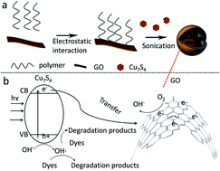
The rational design and control of metal–carbon interface can enhance catalysis,10 then at this point, graphene and related materials such as graphene oxide (GO) have been used to enhance photocatalytic activities. These carbon materials display excellent electronic and mechanical properties, which make them ideal electron-transfer bridges.11,12 Herein, a new type of photocatalyst was prepared by combining Cu7S4 semiconductor with GO (Scheme 1), which demonstrated broadband sunlight absorption and good performance for photodegradation of model compounds (rhodamine, RhB) with excellent reproducibility using real sunlight as irradiation.


image file: c5ra20207h-s1.tif
Scheme 1 Illustration for the formation of Cu7S4@GO NCs and the photodegradation mechanism.

Experimental

Materials and methods

Chloroform, dimethyl sulfoxide (DMSO), NaOH, absolute ethanol, KMnO4, P2O5, K2S2O8, H2SO4, H2O2, HCl, graphite flake, Cu(NO3)2·3H2O were obtained from Beijing Chemical Reagent Company. Methacrylic acid (MAA), styrene (St), and 2,2′-azobis(isobutyronitrile) (AIBN) were supplied by Tianjin Fuchen Chemical Reagents. 1-Allyl-3-methlmidazolium chloride was purchased from Shanghai Flute Cypress Chemical Technology Co. Ltd Dibutyl dithiocarbamate (NNDB) was supplied by Pacific Ocean United (Beijing) Petro-Chemical Co. Ltd All the reagents are of analytical grade and used as received without further purification.

UV-vis-NIR absorption spectra were acquired on a UV-3600 spectrophotometer (Shimadzu) equipped with a plotter unit over the range of wavelength from 300 to 3300 nm. X-ray diffraction (XRD) patterns were measured on a Rigaku SmartLab X-ray diffractometer using Cu Kα radiation (λ = 1.5418 Å) over the range of 2θ from 5° to 90°. Transmission electron microscopy (TEM) images were acquired by using a JEOL JEM-1200EX (200 kV). Roman spectrum was carried out from a Roman-AFM system (Renishaw) with an optical maser wavelength range from 200 to 1000 nm. CEL-HX photoreaction system equipped with a Xe lamp from Beijing Taught Jinyuan Technology Co., Ltd with adjustable diaphragms was used as the irradiation source. Different optical filters were employed to get visible light (420–700 nm), NIR light (>800 nm) and simulated sunlight. The power density was kept the same (1036 mW cm−2) by using optical power meter. The UV-vis-NIR spectrum was measured with powder form under diffuse reflectance mode in an integrating sphere. And the reference compound is BaSO4.

Synthetic procedures

Synthesis of GO. Graphene oxide (GO) was synthesized by a modified Hummers method using expandable graphite flake.13 In a pretreatment process, 8 mL of concentrated H2SO4 was added in a 50 mL beaker and then heated to 90 °C. 1.7 g of K2S2O8 and 1.7 g of P2O5 were then added continuous stirring. Thereafter, the mixture solution was cooled to 80 °C naturally. 2 g of expandable graphite flake was ground with NaCl (50 g) for 5 min to afford tiny graphite flake, in which 250 mL of deionized (DI) water was added, then the tiny graphite flake was obtained by filtration.14 Thereafter, the tiny graphite flake was added to the pre-prepared mixture solution, followed by addition of 330 mL of deionized water, the mixture was kept at 80 °C for 4.5 h and was left to continue stirring overnight. The resulting solid was acquired through filtration and left to dry under ambient conditions on a dish.

In the oxidation step, the pretreated graphite was added to a 1 L flask containing 77 mL of DI H2O, which was put in an ice bath to cool down to 0 °C. Then 10 g of KMnO4 was added slowly so as to maintain the temperature lower than 10 °C. The resulting mixture was kept at 35 °C for 4 h and then at room temperature for another 2 h. Thereafter, the reaction flask was put in ice bath and 150 mL of DI water was added slowly to quench the reaction, and then left to continuously stir for another 2 h. Another 450 mL of DI water was added, quickly followed by addition of 9 mL of 30% H2O2, resulting in a brilliant yellow color appearance. The mixture was centrifuged and washed with 10% HCl solution and then DI water until the gel-like solid was achieved. Finally, the gel-like solid was dispersed in DI water to get the stock solution, the concentration of which was 8 mg mL−1.

Synthesis of positively charged amphiphilic polymer. The positively charged amphiphilic polymer poly-styrene–methacrylic acid–1-allul-3-methylimidazolium chloride (p-St–MAA–AMIM) was prepared according to our previously reported methods.15 First, the monomers styrene (5.1 mL), MAA (46 μL), 1-allyl-2-methylimidazolium chloride (AMIM, 0.368 mg) were added into chloroform (35.0 mL), followed by adding the initiator, 2,2′-azobis(2-methylpropionitrile) (AIBN, 96.0 mg). The mixture was then transferred into a 45 mL Teflon-lined autoclave and heated at 100 °C for 10 h. Then, the polymer was purified by washing with chloroform, precipitating with methanol and centrifuging.
Synthesis of Cu7S4 nanocrystals. The hydrophobic Cu7S4 nanocrystals were prepared by following our previous procedures with minor revision.16–18 First made the precursor Cu(S2CNBut2)2 ready. HS2CNBut2 (20 mg) and Cu(NO3)2·3H2O (0.1 mmol) were mixed in ethanol (1.0 mL) under ultrasonication for 5 min. The resultant green [Cu(S2CNBut2)2] solution was stored at room temperature for later use. 4.0 mL of oleylamine (OAm) and 6.0 mL of 1-octadecene (ODE) was added in a reaction flask with stirring and nitrogen flow. Then heated the mixture to 205 °C followed by injecting 1.0 mL of the as-prepared Cu(S2CNBut2)2 precursor (0.1 mmol). This mixture solution was kept at 190 °C for 20 min and then cooled to 80 °C naturally. The black product was got by precipitating with ethanol and centrifuging and then dispersed in 1.0 mL of chloroform for later use.
Preparation of graphene oxide–polymer complex. In brief, 10 mg of p-St–MAA–AMIM polymer was dissolved in 1 mL of chloroform, then adding to 3 mL of DMSO, followed by addition of 2 mL of GO stock solution. After gently shaking, the complex was precipitated by ethanol and obtained after centrifugation. Finally, 600 μL of chloroform was used to disperse the solid. The AMIM chain on the copolymer has positive charges, while the OH groups on GO render a negative charge surface. Therefore, the graphene oxide–polymer complex was formed through electrostatic interactions.
Preparation of Cu7S4@GO nanocomposites (NCs). Hydrophilic composite nanospheres with various amount of Cu7S4 were obtained through ultrasonication strategy. In a typical case, 3.2 mg of Cu7S4 nanoparticles with an average size of 13 nm, 600 μL of functional copolymer–GO complex were mixed into 1 mL of chloroform. Then, the solution was injected into 10.0 mL of NaOH solution (1 mM) under ultrasonic treatment (300 W). The Cu7S4@GO nanocomposites were got by removing the chloroform at 55 °C for 2 h and centrifuged at 12[thin space (1/6-em)]000 rpm for 10 min. At last, the functional composites were dispersed into DI water and stored for later use. The final concentration of the NCs colloidal solution is 15 mg mL−1. As a control, the NCs without GO were also prepared using the same method.

Results and discussion

The Cu7S4 semiconductor has a broadband absorption (300–3300 nm).16 According to the energy distribution of sunlight, around 54.3%, 38.9% and 6.8% of solar energy at the earth's surface is located in the infrared (760–3000 nm), visible (400–760 nm), and ultraviolet (<400 nm) range, respectively.19,20 Based on this property, we can boost the utilization of solar energy that reaches the earth surface. In addition, the absorbed light energy would induce the electron jumping from valence band (VB) to conduction band (CB),20 which would then be transferred to the combined GO. By taking advantage of the excellent electronic properties of GO, photogenerated electrons could be quickly transferred, resulting in the efficient electron–hole separation.12,21 The photogenerated holes oxidize the hydroxyl groups or water molecules to produce ˙OH radicals while the photogenerated electrons reduce the dissolved oxygen to form superoxide radical anion (˙O2),22 which then reacts with H+ to form the strong oxidation agent ˙OH (Scheme 1).23 The as-formed radicals can oxidize the organic pollutant adsorbed on the surface of the nanocomposites (NCs).24 Another feature is that based on the photothermal properties of Cu7S4, the temperature increased from 30 up to 49 and 77 °C, under the irradiation of real and simulated sunlight, respectively. The increased temperature could also allow electrons to move faster towards the GO,25 promoting the electron–hole separation.

The TEM images (Fig. 1a and b) indicated a nearly monodispersed Cu7S4 nanocrystals with an interplanar distance of 0.194 nm, consistent with the (0,16,0) lattice spacing of anilite Cu7S4,20 which also verified with XRD pattern of Cu7S4 (Fig. 1d). The as-prepared Cu7S4 nanocrystals displayed a broad NIR absorption with maximal absorption around 1500 nm (Fig. 1c). Such broad absorption range would be great useful for sunlight absorption.


image file: c5ra20207h-f1.tif
Fig. 1 TEM images of Cu7S4 (a and b); absorption spectra of hydrophobic Cu7S4, GO, Cu7S4@polymer and Cu7S4@GO NCs (c); the XRD patterns of GO (red line), Cu7S4@GO NCs (blue line) and hydrophobic Cu7S4 (black line).

Given that the GO carries negative charges, an amphiphilic positively charged polymer15 was employed to modify the GO surface beforehand by means of electrostatic interaction. Then the hydrophobic Cu7S4 nanocrystals were wrapped with the as-formed GO–polymer complex to afford Cu7S4@GO NCs. As shown in TEM image (Fig. 2a), Cu7S4 nanocrystals were encapsulated in the GO–polymer complex nanosphere with a rough surface because of GO wrapping. As a control, in the absence of GO, the spherical shape of Cu7S4@polymer NCs was well maintained but the surface was very smooth (Fig. 2b). The different surface roughness preliminarily demonstrates the existence of GO in the NCs. The GO was further proved by Raman spectroscopy. As shown in Fig. 2c, the Raman peaks at ∼1590 cm−1 and ∼1350 cm−1 in the spectrum of NCs are consistent with the D and G peak of GO,26 respectively. The NCs were further characterized via powder X-ray diffraction (XRD) technology (Fig. 1d), which implied the existence of Cu7S4 nanocrystals16,20 and GO.13 After photocatalysis, the initial spherical structures of Cu7S4@GO NCs were well preserved (Fig. 2d), indicating that the NCs were stable in the process of photocatalysis.


image file: c5ra20207h-f2.tif
Fig. 2 TEM images of NCs without (a) and with GO (b); Raman spectra of GO and Cu7S4@GO NCs (c); and TEM image of NCs after photocatalysis (d).

To explore the photocatalytic degradation property of the catalyst, the RhB dye has been chosen as the model compound. The Cu7S4@polymer without GO and Cu7S4@GO NCs were utilized for photodegradation of RhB, respectively. As expected (Fig. 3a), the Cu7S4@GO NCs displayed much enhanced catalytic performance than that of Cu7S4@polymer without GO. After irradiation for 2 h, Cu7S4@GO NCs exhibited excellent activity of 94.7% compared to only 63.6% for Cu7S4@polymer, which may be attributed to easier separation of photogenerated electro–hole pairs in the presence of GO. In addition, the decomposition of RhB could be judged from the colour changes of the solution before and after irradiation treatment (Fig. 3b). It was found that the red colour of RhB disappeared after photodegradation.


image file: c5ra20207h-f3.tif
Fig. 3 (a) Photodegradation evaluation of RhB over NCs without GO and with GO under the irradiation of simulated sunlight; (b) the photos of solution: GO–polymer complex in chloroform (1), Cu7S4@GO NCs colloidal solution (2), Cu7S4@GO NCs colloidal solution mixed with RhB before irradiation treatment (3) and colloidal solution after irradiation treatment (4); (c) photodegradation evaluation of RhB over Cu7S4@GO NCs (15 mg) fabricated with different amount of Cu7S4: 0 mg, 1.6 mg, 3.2 mg, 4.8 mg, 6.4 mg. (d) Photodegradation of RhB over Cu7S4@GO NCs illuminated by visible light, NIR, whole simulated sunlight and real sunlight. C0 and C are the concentration of RhB before and after photodegradation, respectively.

The loading amount of Cu7S4 in the Cu7S4@GO NCs fabrication was also evaluated. Under identical conditions, different amounts (0, 1.6, 3.2, 4.8 and 6.4 mg) of Cu7S4 were adjusted to prepare the NCs. As shown in Fig. 3c, degradation of RhB by Cu7S4@GO NCs was dependent on the amount of Cu7S4NPs. However, there was not much difference when the loading amount was higher than 3.2 mg. For example, under irradiation of 80 min, there was almost no difference between 3.2 mg and 4.8 mg. When the loading further increased to 6.4 mg, merely 3% conversion was increased. Therefore, 3.2 mg of Cu7S4 was used for the following investigation.

Meanwhile, different types of irradiation sources were tested since the photo-induced generation of electron–hole pairs is related to the absorption of photo energy. Under the same power density (1.0 W cm−2), visible light (420–700 nm), NIR light (>800 nm) and whole simulated sunlight were employed and the results were shown in Fig. 3c. The best performance of the photodegradation was found with simulated sunlight either in terms of time or conversion efficiency. Judging from the absorption spectrum of Cu7S4 (Fig. 1c), it is easily found that there is absorption ranging from UV to far NIR region. Thus, the better match between the irradiation source and absorption region of Cu7S4, the more of photons would be absorbed, then the more of electron–hole pairs generated. By using the real sunlight (76 mW cm−2) as irradiation source, these NCs demonstrated fantastic photocatalysis properties (Fig. 3d), indicating their great potential for photodegradation of organic pollutants with large quantities via solar energy rather than the normally used UV lamp.

In another aspect, the repetitive use of a catalyst is highly desirable with concern of its practical applications because of its great potential for ease of separation, continuous processing and catalyst recycling and thereby features green and low-cost.25,27 Therefore, recycling photocatalytic experiments were performed on Cu7S4@GO NCs. As presented in Fig. 4a, the photocatalyst is stable and it can be recovered and reused in multiple cycles for degradation reactions under simulated sunlight irradiation. After being used for fifteen times, it still showed a photodegradation efficiency of 87.99% without obvious decrease. In other words, the Cu7S4@GO NCs reserved activity even with fifteen repeated uses, and the spherical structure was well retained (Fig. 4b).


image file: c5ra20207h-f4.tif
Fig. 4 Recyclability of Cu7S4@GO NCs in photodegradation of RhB (initial concentration of RhB was 10 ppm, Cu7S4@GO NCs 7.5 mg mL−1, the whole volume was 2 mL for each cycle) under simulated sunlight (1.0 W cm−2) (a); TEM image of Cu7S4@GO NCs after 15 cycles of photocatalysis (b).

Conclusions

In summary, the graphene–semiconductor composite nanocatalysts for highly efficient photodegradation of organic compounds have been presented. By combing the broad NIR absorption range of Cu7S4 as well as the excellent electronic properties of GO, the as-prepared Cu7S4@GO NCs displayed an excellent photocatalytic performance even under real sunlight irradiation. Such features hold great potential in pollutant treatment with respect to its facility, high efficiency and cost-effectiveness.

Acknowledgements

This research was supported in part by the National Natural Science Foundation of China (Grant No. 21475007, 21275015 and 21505003). We also thank the support from the “Innovation and Promotion Project of Beijing University of Chemical Technology”, the “Public Hatching Platform for Recruited Talents of Beijing University of Chemical Technology, and the High-Level Faculty Program of Beijing University of Chemical Technology (buctrc201507)”.

Notes and references

  1. H. Tong, S. X. Ouyang, Y. P. Bi, N. Umezawa, M. Oshikiri and J. H. Ye, Adv. Mater., 2012, 24, 229–251 CrossRef CAS PubMed.
  2. S. Bai, J. Jiang, Q. Zhang and Y. J. Xiong, Chem. Soc. Rev., 2015, 44, 2893–2939 RSC.
  3. S. Linic, P. Christopher and D. B. Ingram, Nat. Mater., 2011, 10, 911–921 CrossRef CAS PubMed.
  4. S. Sakthivel and H. Kisch, Angew. Chem., Int. Ed., 2003, 42, 4908–4911 CrossRef CAS PubMed.
  5. R. E. Blankenship, D. M. Tiede, J. Barber, G. W. Brudvig, G. Fleming, M. Ghirardi, M. R. Gunner, W. Junge, D. M. Kramer, A. Melis, T. A. Moore, C. C. Moser, D. G. Nocera, A. J. Nozik, D. R. Ort, W. W. Parson, R. C. Prince and R. T. Sayre, Science, 2011, 332, 805–809 CrossRef CAS PubMed.
  6. I. Cesar, K. Sivula, A. Kay, R. Zboril and M. Graetzel, J. Phys. Chem. C, 2009, 113, 772–782 CAS.
  7. J. R. Maiolo, B. M. Kayes, M. A. Filler, M. C. Putnam, M. D. Kelzenberg, H. A. Atwater and N. S. Lewis, J. Am. Chem. Soc., 2007, 129, 12346–12347 CrossRef CAS PubMed.
  8. Y. D. Hou, B. L. Abrams, P. C. K. Vesborg, M. E. Bjorketun, K. Herbst, L. Bech, A. M. Setti, C. D. Damsgaard, T. Pedersen, O. Hansen, J. Rossmeisl, S. Dahl, J. K. Norskov and I. Chorkendorff, Nat. Mater., 2011, 10, 434–438 CrossRef CAS PubMed.
  9. J. Goldberger, R. R. He, Y. F. Zhang, S. W. Lee, H. Q. Yan, H. J. Choi and P. D. Yang, Nature, 2003, 422, 599–602 CrossRef CAS PubMed.
  10. Z. C. Zhang, B. Xu and X. Wang, Chem. Soc. Rev., 2014, 43, 7870–7886 RSC.
  11. N. Zhang, Y. H. Zhang and Y. J. Xu, Nanoscale, 2012, 4, 5792–5813 RSC.
  12. I. V. Lightcap, T. H. Kosel and P. V. Kamat, Nano Lett., 2010, 10, 577–583 CrossRef CAS PubMed.
  13. D. C. Marcano, D. V. Kosynkin, J. M. Berlin, A. Sinitskii, Z. Z. Sun, A. Slesarev, L. B. Alemany, W. Lu and J. M. Tour, ACS Nano, 2010, 4, 4806–4814 CrossRef CAS PubMed.
  14. X. M. Sun, Z. Liu, K. Welsher, J. T. Robinson, A. Goodwin, S. Zaric and H. J. Dai, Nano Res., 2008, 1, 203–212 CrossRef CAS PubMed.
  15. M. Bai, X. L. Bai and L. Y. Wang, Anal. Chem., 2014, 86, 11196–11202 CrossRef CAS PubMed.
  16. J. B. Cui, R. Jiang, S. Y. Xu, G. F. Hu and L. Y. Wang, Small, 2015, 11, 4183–4190 CrossRef CAS PubMed.
  17. S. Huang, J. Liu, Q. He, H. L. Chen, J. B. Cui, S. Y. Xu, Y. L. Zhao, C. Y. Chen and L. Y. Wang, Nano Res., 2015 DOI:10.1007/s12274-015-0905-9.
  18. J. B. Cui, S. Y. Xu, C. Guo, R. Jiang, T. D. James and L. Y. Wang, Anal. Chem., 2015 DOI:10.1021/acs.analchem. 5b03652.
  19. S. Cho, M. J. Lee, M. S. Kim, S. Lee, Y. K. Kim, D. H. Lee, C. W. Lee, K. H. Cho and J. H. Chung, J. Dermatol. Sci., 2008, 50, 123–133 CrossRef CAS PubMed.
  20. J. B. Cui, Y. J. Li, L. Liu, L. Chen, J. Xu, J. W. Ma, G. Fang, E. B. Zhu, H. Wu, L. X. Zhao, L. Y. Wang and Y. Huang, Nano Lett., 2015, 11, 4183–4190 CAS.
  21. N. J. Bell, H. N. Yun, A. J. Du, H. Coster, S. C. Smith and R. Amal, J. Phys. Chem. C, 2011, 115, 6004–6009 CAS.
  22. K. Rajeshwar, M. E. Osugi, W. Chanmanee, C. R. Chenthamarakshan, M. V. B. Zanoni, P. Kajitvichyanukul and R. Krishnan-Ayer, J. Photochem. Photobiol. C-Photochem. Rev., 2008, 9, 171–192 CrossRef CAS.
  23. E. Casbeer, V. K. Sharma and X. Z. Li, Sep. Purif. Technol., 2012, 87, 1–14 CrossRef CAS.
  24. T. T. Lim, P. S. Yap, M. Srinivasan and A. G. Fane, Crit. Rev. Environ. Sci. Technol., 2011, 41, 1173–1230 CrossRef CAS.
  25. Z. X. Gan, X. L. Wu, M. Meng, X. B. Zhu, L. Yang and P. K. Chu, ACS Nano, 2014, 8, 9304–9310 CrossRef CAS PubMed.
  26. H. B. Feng, R. Cheng, X. Zhao, X. F. Duan and J. H. Li, Nat. Commun., 2013, 4, 1539 CrossRef PubMed.
  27. Y. E. Wu, D. S. Wang and Y. D. Li, Chem. Soc. Rev., 2014, 43, 2112–2124 RSC.

This journal is © The Royal Society of Chemistry 2015