Protoporphyrin incorporated alginate hydrogel: preparation, characterization and fluorescence imaging in vivo

Xia Dong , Chang Wei, Tianjun Liu and Feng Lv*
Tianjin Key Laboratory of Biomedical Materials, Institute of Biomedical Engineering, Chinese Academy of Medical Sciences & Peking Union Medical College, Tianjin 300192, PR China. E-mail: lvfeng2002@163.com; Fax: +86-22-87893236; Tel: +86-22-87893236

Received 18th September 2015 , Accepted 26th October 2015

First published on 27th October 2015


Abstract

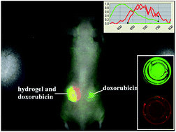
Fluorescence imaging provides a non-invasive tool for locating, monitoring and tracking implanted biomaterials in situ. Since alginate hydrogels have been widely applied as scaffolds for tissue engineering, delivery carriers or extracellular matrices, the in vivo status of alginate hydrogels is necessary and important to their applications. Herein, a protoporphyrin incorporated alginate hydrogel was prepared using PEG as a linker. The structure and properties were investigated with rheological analysis, thermogravimetric analysis, and UV-visible and fluorescence spectrophotometry. Hydrogel erosion and drug delivery in vivo were monitored and tracked using a multispectral fluorescence imaging system with nude mice as models. The results show that the protoporphyrin incorporated alginate hydrogel exhibits fluorescence ability in vivo with good biocompatibility. With the guidance of fluorescence imaging, the in vivo status of hydrogels can be reflected in situ. Protoporphyrin based biomaterials have potential for application in in vivo monitoring and tracking using fluorescence imaging.


1. Introduction

As a representative implanted biomaterial with a hydrophilic polymer network, hydrogels are widely applied in the fields of soft tissue engineering, drug delivery, surgical implants and so on.1–3 The success of implanted biomaterials depends on the synchronization of the material’s status in vivo and the therapeutic effects. It is important and essential to understand the in vivo status and processes of metabolism, distribution and degradation, which are relative to the environmental influences of biotissue. There are various techniques to investigate the in vivo status and processes including thermogravimetric analysis (TGA), 1H-NMR spectroscopy, gel permeation chromatography (GPC), high-performance liquid chromatography (HPLC), Fourier transform infrared spectroscopy (FTIR), histological analysis and immunohistochemical analysis.4–7 However, these methods are inherently destructive to samples in vitro or ex vivo and do not allow for an accurate volume assessment about the information on the functional status in situ. Accordingly, there is a great need for the development of a non-invasive and real-time tool to implement the monitoring and assessing of biomaterials in situ.

Imaging technologies in situ have been developed as a strategic priority for the monitoring of implanted biomaterials because of their real-time, non-destructive, longitudinal, quantitative and three dimensional analyses.8,9 Traditional imaging modalities, including ultrasonography (US), computed tomography (CT), SPECT and magnetic resonance imaging (MRI), have shown a broad range of applications in the evaluation of biomaterials in vivo.10–12 In addition, fluorescence imaging has attracted increasing attention as a potential and advanced tool for online non-destructive biomaterial characterization owing to its easy setup, low cost, high sensitivity, low-energy radiation, non-invasiveness and ability for long-term observation.13,14 For example, fluorescence imaging was expanded to long-term in vivo glucose monitoring with fluorescent hydrogel fibers or microbeads by Heo and Shibata.15,16 Selvam and Liu reported that biomaterial-associated inflammation can be monitored with minimally invasive and longitudinal fluorescence imaging.17,18 This can detect the reactive oxygen species released by inflammatory cells in response to an implant. Zhang et al. investigated fluorescent biomaterials for bone tissue engineering and monitored bone regrowth replacing the implant in vivo using fluorescence imaging.19 Especially, multispectral fluorescence imaging can track two or more fluorescent probes simultaneously to monitor the biological fate of biomaterials and track drug delivery, which is a conspicuous advantage compared to other imaging modalities.20 In order to further develop fluorescent biomaterials for imaging in vivo, fluorescent tagging is the key basis for fluorescence imaging.

Porphyrin compounds have been considered as fluorescent tags due to their large visible and near infrared absorptions, molar extinction constants, acceptable fluorescence quantum yields and excellent biocompatibilities.21,22 Fluorescence imaging with porphyrin attracts our research interest and several glucose conjugated porphyrin compounds have been investigated for in vivo imaging.23,24 Among porphyrin compounds, protoporphyrin is a special porphyrin compound with an important physiological function as the main ingredient of hemoglobin, which brings favorable biocompatibility, exceeding other synthetic porphyrin compounds. Protoporphyrin compounds generally are generated as ideal oxygen carriers or photodynamic therapy agents,25,26 while their application in fluorescence imaging as fluorescent tags was considerably constrained because of aggregation from π-stacking and hydrophobic interactions in aqueous media, which directly leads to faint fluorescence. Therefore, protoporphyrin based biomaterials face a potential challenge for in vivo monitoring and tracking using fluorescence imaging.

As alginate is a natural type of polysaccharide compound, it gives the advantage of beneficial biocompatibility. Alginate hydrogels have been widely applied as scaffolds for tissue engineering, delivery carriers or extracellular matrices.27,28 In the present study, a protoporphyrin incorporated alginate (PPOR-alginate) hydrogel was prepared with PEG as a linker. The structure and properties were investigated with rheological analysis, thermogravimetric analysis (TGA), and UV-visible and fluorescence spectrophotometry. Hydrogel erosion and drug delivery in vivo were monitored and tracked using a multispectral fluorescence imaging system with nude mice as models.

2. Experimental section

2.1 Materials

Protoporphyrin (≥95%, Aladin) was provided by Shanghai Jingchun biotech corporation. Poly(ethylene glycol) (PEG, Mn = 1000, Merck) was vacuum-dried at 60 °C for 12 hours before use. Sodium alginate (AR) was provided by Shanghai Jingchun biotech corporation. Other reagents were all of analytic reagent (AR) grade.

Nude mice (seven weeks old, 20–25 g) were used. All the animal experiments were performed in compliance with the Guiding Principles for the Care and Use of Laboratory Animals, Peking Union Medical College, China. The animals had free access to food and water.

2.2 Synthesis of the PPOR-alginate copolymer

The PPOR-alginate copolymer was prepared according to Fig. 1. PEG 1000 (4 g) was reacted with protoporphyrin (40 mg) in DMF (20 mL) at room temperature for 24 hours under catalysis by 1-(3-dimethylaminopropyl)-3-ethylcarbodiimide hydrochloride (EDC) and 4-dimethylaminopryidine (DMAP). The reacted solution was washed with water, precipitated with cool ether and dried under vacuum to give the crude protoporphyrin-conjugated PEG. Then it was purified to remove the PEG molecules using dialysis. Next, protoporphyrin-conjugated PEG (0.5 g) and sodium alginate (0.5 g) were reacted under catalysis by EDC and DMAP in water solution (50 mL) at room temperature for 24 hours. The mixture was then precipitated with methanol ether, filtered and dried to provide the PPOR-alginate copolymer.
image file: c5ra19285d-f1.tif
Fig. 1 Synthetic route of protoporphyrin incorporated alginate.

2.3 Characterization of the PPOR-alginate copolymer

Infrared spectra were recorded using FTIR on a Nicolet 2000 instrument from 4000 to 400 nm−1 with an attenuated total reflectance (ATR) device. The copolymer films underwent infrared spectra analysis with ATR. 1H-NMR spectra were recorded on a VARIAN INOVA instrument at 500 MHz using D2O as solvent and TMS as an internal reference.

2.4 Gelation response time and swelling behavior of the hydrogel

The calcium PPOR-alginate hydrogel was prepared through the crosslinking of CaCl2 in sodium PPOR-alginate solution. Rheological measurements about the gelation response time of the hydrogel were carried out using a rheometer (MCR 302, Anton-paar, Austria). The copolymer aqueous solution (2 wt%) was placed between vertebral plates of 20 mm diameter, and then was added to a CaCl2 solution to form a hydrogel. The storage modulus (G′) and loss modulus (G′′) were measured under an angular frequency of 6.28 Hz. TGA (Q500, TA instruments, USA) was used to analyze the swelling behavior of the calcium PPOR-alginate hydrogel over a temperature range from 20 to 150 °C under a nitrogen atmosphere at a heating and cooling rate of 5 °C min−1.

2.5 Optical measurements in vitro

UV-vis spectra of the calcium PPOR-alginate film were obtained with a solid sample using a UV/VIS spectrometer (Lambda 35, PerkinElmer, USA). The fluorescence imaging of the hydrogel in vitro was performed using an in vivo imaging system (Maestro EX, CRI, USA).

2.6 Morphology of the hydrogel before injection and after erosion

Scanning electron microscopy (SEM) (S4800, Hitachi, Japan) was employed to observe the morphology of the hydrogel. The samples were chosen before injection and after the erosion of the hydrogel for 21 days. They were frozen in liquid nitrogen and lyophilized for 72 hours, then were observed after gold sputtering.

2.7 Cytotoxicity assessment

Murine fibroblast cell line L929 cells were cultured in Roswell Park Memorial Institute 1640 medium (HyClone Laboratories, Inc., Logan, UT, USA) supplemented with 10% fetal bovine serum, 2 mM L-glutamine, 100 units per mL penicillin, and 100 μg mL−1 streptomycin, and incubated at 37 °C in a humidified incubator with 5% CO2. The viability of the L929 cells after 24 hours of incubation with different concentrations of the PPOR-alginate copolymer (25, 50, 100, 200, and 400 μg mL−1) was assessed with a Cell Counting Kit-8 (Dojindo Molecular Technologies, Inc., Kumamoto, Japan), with untreated cells serving as the experimental control. The cell viability was presented as the ratio of the OD450 of the PPOR-alginate copolymer-treated cells to that of the untreated cells. Six wells were measured for each test.

2.8 Multispectral fluorescence imaging for drug delivery from the hydrogel

Multispectral imaging was carried out to track the carrier and drug using the Maestro in vivo imaging system from CRI. A water soluble fluorescent drug, doxorubicin, was chosen as a model drug. The excitation wavelength was set at 535 nm or 595 nm based on the difference in the fluorescent compounds. The drug and carrier can be distinguished according to the difference in excitation and emission. The Maestro software was used to separate the spectral species from the cube file and overlay the single compound with green and red. The unmixed grayscale images of single components from the drug can be calculated quantitatively. The in vivo imaging was recorded to track the release of the drug for 5 days.

2.9 Fluorescence tracking for degradation in vivo and organ distribution ex vivo

Nude mice were randomly assigned to a subcutaneous injection group or a control group (n = 3 for each group). In the experimental group, 100 μL of an aqueous solution of sodium PPOR-alginate copolymer and 10 μL of CaCl2 solution at a concentration of 2% were injected to form a calcium PPOR-alginate hydrogel in the subcutaneous tissue of the back. The in vivo imaging was recorded after administration from 0 to 21 days. At predetermined time points, the mice were anesthetized by an intraperitoneal injection of chloral hydrate at a concentration of 4%. Imaging was done using a CRI imaging system with an exposure time of 400 ms. The excitation wavelength was set at 595 nm and the emission wavelength was chosen from 635 nm to 800 nm. At the end of the imaging, the anesthetized mice were sacrificed and imaging of the organs was done to evaluate the distribution of fluorescent materials. Fluorescence images of organs were analyzed using the CRI Analysis Software. After imaging, the organ tissues were immediately immersed into phosphate-buffered saline with 4% formaldehyde at pH 7.4 and 4 °C for 24 hours. Then, they were stained using hematoxylin–eosin after immobilization and sectioned.

3. Results and discussion

3.1 Preparation and structural characterization of the protoporphyrin incorporated alginate copolymer

Protoporphyrin incorporated alginate was synthesized with simple and convenient crosslinking as seen in Fig. 1. Based on the cross-linking of protoporphyrin and PEG, the alginate segments were linked to protoporphyrin using PEG as a linker. The introduction of the PEG molecule can avoid the single molecule aggregation of protoporphyrin, and then the fluorescence of protoporphyrin can be applied to track and monitor the hydrogel. Generally, porphyrin hydrogels also can be prepared by physical encapsulation or surface absorption and porphyrin tends to be released from the hydrogel as an active drug without enough stability from the backbone of the hydrogel.29,30 While in order to track the hydrogel in situ, protoporphyrin can not be cut off from chemically cross-linked porphyrin hydrogels with superordinary stability after conjugation with a chemical covalent bond. Because protoporphyrin and the polymer are covalently linked to each other, the change of tag can stand in direct correlation to the degradation of the polymer.

The PPOR-alginate copolymer is a red compound with the typical appearance of porphyrin. The chemical structure of the PPOR-alginate copolymer was characterized by FT-IR and 1H-NMR spectroscopy. As shown in Fig. S1, the FTIR spectra of protoporphyrin, alginate and PPOR-alginate, the characteristic peaks of the alginate and PEG segments are shown in the spectra of the two copolymers. The peaks at 3400, 2900, 1600 and 1100 cm−1 are the signals of the –OH, –CH2, –CO and –C–O–C bands, respectively. Although porphyrin has its characteristic peaks of –COOH and C[double bond, length as m-dash]C, its weak signals of a lower ratio in the PPOR-alginate copolymer can not be observed with the overlay of the other characteristic peaks. The 1H-NMR spectra further verify the structure of the PPOR-alginate copolymer. As seen in the spectrum of PPOR-alginate (Fig. S2), the characteristic peaks from 3.5 ppm to 4.2 ppm are attributed to the protons of the saccharide unit in the chain of alginate. The signal of –CH2CHO– at 3.53 ppm is the characteristic peak of the PEG unit. Besides, there are two minor peaks at 6.6 ppm and 7.8 ppm, which are the characteristic peaks of protoporphyrin. They signify the vinyl Hβ trans to porphyrin and the Hα trans to porphyrin, respectively. Other characteristic peaks cannot be observed due to their low signals. All these signals confirm the successful synthesis of the PPOR-alginate copolymer.

3.2 Optical characterization of the protoporphyrin incorporated alginate copolymer and hydrogel in vitro

The absorption spectra of calcium alginate and its derivates can only be detected using solid samples because they are water insoluble solid gels. As shown in the UV-vis spectrum of the calcium PPOR-alginate copolymer (Fig. S3), the typical absorption peaks of porphyrin compounds are displayed with an intense Soret band at 420 nm and weak wide Q-bands from 540 nm to 680 nm in the near-infrared region. The intensities and widths of the characteristic absorption bands are different to other porphyrin copolymers in water solution. Water solutions of protoporphyrin copolymers generally show a sharp peak at 420 nm and two weak wide Q-bands at 540 nm and 600 nm in the near-infrared region. The change of porphyrin peaks in the porphyrin polymer mainly comes from the molecular status of the porphyrin polymer. The Q-band absorption of the PPOR-alginate copolymer is suitable for in vivo imaging because the optical signal of shorter wavelength is rapidly attenuated in biotissue. In order to meet the requirements for in vivo imaging, with low autofluorescence and background interference, a longer wavelength is more beneficial for in vivo imaging.

The fluorescence imaging in vitro of the calcium PPOR-alginate copolymer and protoporphyrin water solution is as shown in Fig. 2. The intense fluorescence of the calcium PPOR-alginate copolymer can be seen while the water solution of protoporphyrin has little emission due to molecular aggregation. Generally, porphyrin compounds tend to aggregate due to π-stacking and hydrophobic interactions with the self-quenching of fluorescence in water solution. But after modification with a macromolecular chain, a high density of protoporphyrin is spatially enforced to prevent molecular self-quenching. Accordingly, the calcium PPOR-alginate copolymer shows the obvious emission of a porphyrin compound. Other porphyrin-cross-linked hydrogels also agree with this phenomenon.31 The emission of the PPOR-alginate copolymer makes it suitable for in vivo imaging.


image file: c5ra19285d-f2.tif
Fig. 2 Fluorescence imaging in vitro (A) and photograph of the hydrogel (B).

3.3 Gelation response time and swelling behavior of the hydrogel

The gelation response time of the calcium PPOR-alginate hydrogel was measured using rheological analysis (Fig. S4). The change in elastic modulus (G′) and viscous modulus (G′′) reflect the sol–gel transition of the PPOR-alginate hydrogel with the introduction of calcium ions. Before the cross linking of the calcium ions, the elastic modulus (G′) of PPOR-alginate is lower than the viscous modulus (G′′), which signifies the sol state of the copolymer. But with the addition of calcium ions, the elastic modulus (G′) and viscous modulus (G′′) are increased conspicuously and immediately, and the viscous modulus (G′′) was exceeded by the elastic modulus (G′). This demonstrates that the gelation response time of alginate–PEG-PPOR is less than 5 seconds with a fast sol–gel transition. The swelling behavior of the hydrogel was evaluated with the evaporation of water in the hydrogel by TGA. With the increase in the temperature, the water in the hydrogel is evaporated firstly and calcium PPOR-alginate still remains. According to the weight change of the hydrogel from the curve of TGA (Fig. S5), the weight of the hydrogel has a reduction of 97.82% from the evaporation of water, and calcium PPOR-alginate has a remnant of 2.18%. The result suggests that the swelling ratio of the calcium PPOR-alginate hydrogel is about 45 fold.

3.4 Biocompatibility of the protoporphyrin-incorporated alginate copolymer

Although each ingredient of the calcium PPOR-alginate hydrogel has been proved to have good biocompatibility and low toxicity, the cell biocompatibility evaluation of PPOR-alginate as a biomedical material is indispensable. The cellular survival rate was measured using the Cell Counting kit-8 assay (Fig. 3). The results show that the copolymer solution did not cause obvious cell toxicity over the concentration range from 25 to 200 μg mL−1; even 24 hours of exposure to 400 μg mL−1 PPOR-alginate hydrogel does not lead to significantly decreased cell viability (more than 70%). It offers excellent biocompatibility because of the intrinsic nature of the raw materials.
image file: c5ra19285d-f3.tif
Fig. 3 Biocompatibility of the protoporphyrin-incorporated alginate copolymer using the CCK-8 method.

3.5 Multispectral fluorescence imaging for drug delivery from the hydrogel

Based on the fact that the spectrum is different for each specific fluorescent material, multispectral fluorescence imaging can track two or more fluorescent probes simultaneously. This is a unique function that other imaging techniques can not provide. A multicolor composite image can be generated to distinguish different labels using highly contrasting colors to represent the location of each probe. Accordingly, multispectral fluorescence imaging can be used for monitoring and tracking the biological fate of biomaterials and drug delivery.32–34 The location and status of the drug and carrier can be provided clearly and simultaneously. As an anti-cancer drug with fluorescence signals, doxorubicin can be monitored in a fluorescent protoporphyrin incorporated alginate hydrogel using multispectral fluorescence imaging in vivo. Due to the fluorescence difference between protoporphyrin incorporated alginate hydrogel and doxorubicin, they can be obviously distinguished as red and green respectively by the multispectral fluorescence technique, (Fig. 4). As shown in the in vivo imaging of the drug delivery (Fig. 5), free doxorubicin is rapidly distributed and metabolized after 24 hours without persistent retention at the administration site, such that the fluorescence of doxorubicin decreases obviously. While in the site with the drug-loaded hydrogel, the fluorescence intensity of doxorubicin decreases gradually with continued diffusion due to the drug release, the fluorescence signal still remained after delivery for 5 days. This shows a conspicuous sustained release in comparison with free doxorubicin. The in situ process of drug release from hydrogels can be viewed evidently by multicolor imaging. Multispectral analysis provides the ability to locate the drug and carrier respectively and separates the autofluorescence signals from the specific labels.
image file: c5ra19285d-f4.tif
Fig. 4 Multispectral fluorescence imaging for the location of the hydrogel (red) and doxorubicin (green) (inset: fluorescence spectra and imaging of the hydrogel and doxorubicin).

image file: c5ra19285d-f5.tif
Fig. 5 Fluorescence analysis of drug delivery from the hydrogel; a representative of one of three from each group is given.

Multispectral fluorescence imaging provides a more objective evaluation for a drug delivery system. Fluorescence imaging in vivo has shown its ability to track the release of drugs because of its advantage of being able to monitor for a long time.35,36 Due to limiting conditions, general evaluation in vitro tends to not be highly accurate for the release effect in vivo, including the analysis of blood samples by HPLC or the radioactive detection of labeled drugs. Moreover, these methods require a much greater number of animals than the in vivo fluorescence imaging method while they still do not bring improved quality of data. Here, according to the fluorescence difference between PPOR-alginate and doxorubicin, the release and location can be obviously distinguished using the multispectral fluorescence technique.

3.6 Fluorescence tracking for degradation in vivo

In order to monitor and track the implanted hydrogel in vivo, whole animal fluorescence imaging was performed on nude mice using subcutaneous injection in the back. The hydrogel can be located in the targeted area or by surgical resection with fluorescence image guiding in vivo. As shown in Fig. 6, the intense fluorescence signals of the hydrogel can be observed in the emission range from 630 nm to 800 nm at the excitation wavelength of 595 nm. The excitation and emission wavelengths can affect the quality of fluorescence imaging. Since the biological chromophore hemoglobin and other biological components including water and lipids will bring weak background interference in the near infrared region, the emission range from 630 nm to 800 nm is a suitable optical window for in vivo imaging at the excitation wavelength of 595 nm.
image file: c5ra19285d-f6.tif
Fig. 6 Fluorescence imaging and locating of the calcium PPOR-alginate hydrogel; a representative of one of three in each group is given.

Moreover, the erosion of the hydrogel was also monitored from the total fluorescence decay using a non-invasive CRI imaging system. Fluorescence imaging of living animals was performed in mice for three weeks (Fig. 7). By the comparison of the fluorescence images from a period of 0 to 21 days, the fluorescence signals of the hydrogel decrease gradually with the permeation and distribution of the hydrogel. After permeation for 4 days, the fluorescence of the hydrogel shrinks obviously. The fluorescence signal can remain at less than 10% of the total fluorescence after two weeks. But after degradation and metabolism for 21 days, the hydrogel displays very faint fluorescence in contrast with the prior fluorescence. From the comparison of the fluorescence imaging, these data reveal that the erosion rate of the hydrogel is rapid in the first 4 days after injection. The definite judgement of the hydrogel erosion demonstrates the potential for the strategic adjustment of the composition and structure to meet specific requirements. Actually, such a model of subcutaneous administration would partly predict the in vivo erosion kinetics of newly synthesized hydrogel materials. As the subcutaneous space of a mouse has a limited fluid volume, it is inevitably different from the other tissue. For example, the intraperitoneal cavity is significantly larger with a higher volume of fluids than the subcutaneous tissue. Thus, the erosion of the hydrogel may be varied with the implant site.


image file: c5ra19285d-f7.tif
Fig. 7 Fluorescence imaging of the calcium PPOR-alginate hydrogel in vivo at different times; a representative of one of three in each group is given (left: hydrogel group; right: control).

In fact, the tracking and monitoring of the material status in vivo tend to be challenging. The material status and fate varies with the dimensions, crosslinking, composition and environmental conditions. Although the structure and composition of materials in vitro could be coherent with those in vivo, the environment of biotissue in vivo can not be represented by that in vitro. Fluorescence incorporated biomaterials provide an advanced and effective tool for the tracking and monitoring of biomaterials. Fluorescence tracking in vivo for the degradation of implanted biomaterials can not only reduce the number of samples, but also obtain multiple-time-point information by the consecutive tracking of one sample. Moreover, multiple tags can enable independent tracking and correlation of drug release, material erosion or the fate of cells and materials within tissue-engineered formulations. Here, a preliminary investigation is performed about the drug release and materials erosion of an alginate hydrogel, then a more detailed study needs to elucidate further the interaction between cells, drugs and materials.

The clinical fluorescence imaging agents mainly include indocyanine green and methylene blue, which exhibit obvious effects for fluorescence labeling and imaging,37,38 while their applications tend to be seriously limited owing to their disadvantages, including complex synthesis, high cost and low quantum efficiency. Apart from these, conventional fluorescent agents including rhodamine compounds and lucifer yellow are usually applied for the labelling of implanted hydrogels due to the convenience of dosage and preparation.39,40 Compared with other fluorescent dyes, porphyrins provide feasibility and superiority for in vivo imaging as fluorescence tags because of their excellent biocompatibility. The presence of porphyrin in the polymer backbone not only avoids the breakage of fluorescent tags and ensures a feasible fluorescence efficiency but also decreases the adverse effects on biotissue from fluorescent dyes. Among porphyrin compounds, the development of protoporphyrin as a fluorescence tag may face a challenge due to fluorescence quenching from molecular aggregation. In our fluorescent hydrogel, the protoporphyrin conjugated polymer gives acceptable fluorescence from the molecular disaggregation of PEG and alginate. It establishes an innovative method for implants with fluorescence imaging in vivo.

3.7 Organ distribution ex vivo and morphology of the hydrogel

To further elucidate the organ distribution and the status of the hydrogel, the ex vivo fluorescence signals of key organs including the heart, liver, spleen, lung, kidney, and skin of the administering site were collected after the mice were sacrificed after three weeks. In the subcutaneous tissue of the experimental mice, the undegraded hydrogel still obviously exists under the skin with a strong fluorescence ex vivo, while there are only low fluorescence signals in other organs (Fig. 8). This demonstrates that the hydrogel mainly permeates the tissue with a slow metabolism process.
image file: c5ra19285d-f8.tif
Fig. 8 Organ distribution of the calcium PPOR-alginate hydrogel.

SEM was employed to observe the morphology of the residual hydrogel situated under the skin in order to investigate the structure of the hydrogel after erosion. The surface of the residual hydrogel shows inhomogeneous cracks and links while the initial hydrogel presents a compact structure (Fig. 9). This reflects that the hydrogel is eroded by the action of enzymes and other biomolecules. Besides, the in vivo biocompatibility and safety of the hydrogel was assessed by histological analysis of biotissue and key organs. There are no significant inflammatory reactions and histopathological changes to the skin of the administering site according to the HE staining shown in Fig. 10. This suggests the good biocompatibility and biosafety of the hydrogel in vivo because there are no obvious histopathological changes or abnormal damage to the key organs.


image file: c5ra19285d-f9.tif
Fig. 9 SEM of the hydrogel (A) and degraded hydrogel (B).

image file: c5ra19285d-f10.tif
Fig. 10 Histological sections of major organs after the subcutaneous administration of the calcium PPOR-alginate hydrogel (A–F) and major organs of the control group (G–L) (×40) (A and F: heart; B and H: liver; C and I: spleen; D and J: lung; E and K: kidney; F and L: skin).

4. Conclusion

In summary, a protoporphyrin incorporated alginate hydrogel was successfully prepared through the conjugation of alginate and protoporphyrin using PEG as a linker. With the guidance of fluorescence imaging, the in vivo status of the hydrogel can be reflected in situ. The protoporphyrin incorporated alginate hydrogel exhibits fluorescence ability in vivo with good biocompatibility. Protoporphyrin based biomaterials will have a potential application for in vivo monitoring and tracking by fluorescence imaging.

Acknowledgements

This work was supported by the National Natural Science Foundation of China (No. 31200732) and the Natural Science Foundation of Tianjin, China (No. 14JCYBJC17400).

References

  1. K. Deligkaris, T. S. Tadele, W. Olthuis and A. van den Berg, Sens. Actuators, B, 2010, 147, 765–774 CrossRef CAS.
  2. C. He, S. W. Kim and D. S. Lee, J. Controlled Release, 2008, 127, 189–207 CrossRef CAS PubMed.
  3. Y. Li, J. Rodrigues and H. Tomas, Chem. Soc. Rev., 2012, 41, 2193–2221 RSC.
  4. Y. C. Fu, T. F. Fu, H. J. Wang, C. W. Lin, G. H. Lee, S. C. Wu and C. K. Wang, Acta Biomater., 2014, 10, 4583–4596 CrossRef CAS PubMed.
  5. J. S. Loo, C. P. Ooi and F. Y. Boey, Biomaterials, 2005, 26, 1359–1367 CrossRef CAS PubMed.
  6. C. Rentsch, W. Schneiders, S. Manthey, B. Rentsch and S. Rammelt, Biomatter, 2014, 4, e27993 CrossRef PubMed.
  7. A. Subramanian, U. M. Krishnan and S. Sethuraman, BioMed Res. Int., 2013, 2013, 390518 Search PubMed.
  8. A. A. Appel, M. A. Anastasio, J. C. Larson and E. M. Brey, Biomaterials, 2013, 34, 6615–6630 CrossRef CAS PubMed.
  9. S. Y. Nam, L. M. Ricles, L. J. Suggs and S. Y. Emelianov, Tissue Eng., Part B, 2015, 21, 88–102 CrossRef PubMed.
  10. S. F. Fischerauer, T. Kraus, X. Wu, S. Tangl, E. Sorantin, A. C. Hanzi, J. F. Loffler, P. J. Uggowitzer and A. M. Weinberg, Acta Biomater., 2013, 9, 5411–5420 CrossRef CAS PubMed.
  11. S. F. Othman, E. T. Curtis, S. A. Plautz, A. K. Pannier, S. D. Butler and H. Xu, NMR Biomed., 2012, 25, 452–463 CrossRef PubMed.
  12. L. Solorio, B. M. Babin, R. B. Patel, J. Mach, N. Azar and A. A. Exner, J. Controlled Release, 2010, 143, 183–190 CrossRef CAS PubMed.
  13. J. Rao, A. Dragulescu-Andrasi and H. Yao, Curr. Opin. Biotechnol., 2007, 18, 17–25 CrossRef CAS PubMed.
  14. Y. Zhang and J. Yang, J. Mater. Chem. B, 2013, 1, 132–148 RSC.
  15. Y. J. Heo, H. Shibata, T. Okitsu, T. Kawanishi and S. Takeuchi, Proc. Natl. Acad. Sci. U. S. A., 2011, 108, 13399–13403 CrossRef CAS PubMed.
  16. H. Shibata, Y. J. Heo, T. Okitsu, Y. Matsunaga, T. Kawanishi and S. Takeuchi, Proc. Natl. Acad. Sci. U. S. A., 2010, 107, 17894–17898 CrossRef CAS PubMed.
  17. W. F. Liu, M. Ma, K. M. Bratlie, T. T. Dang, R. Langer and D. G. Anderson, Biomaterials, 2011, 32, 1796–1801 CrossRef PubMed.
  18. S. Selvam, K. Kundu, K. L. Templeman, N. Murthy and A. J. Garcia, Biomaterials, 2011, 32, 7785–7792 CrossRef CAS PubMed.
  19. Q. Zhang, V. N. Mochalin, I. Neitzel, I. Y. Knoke, J. Han, C. A. Klug, J. G. Zhou, P. I. Lelkes and Y. Gogotsi, Biomaterials, 2011, 32, 87–94 CrossRef CAS PubMed.
  20. L. Zhou and W. S. El-Deiry, J. Nucl. Med., 2009, 50, 1563–1566 CrossRef PubMed.
  21. C. Vijay Kumar, L. Cabau, E. N. Koukaras, G. D. Sharma and E. Palomares, Nanoscale, 2015, 7, 179–189 RSC.
  22. Y. Zhang and J. F. Lovell, Theranostics, 2012, 2, 905–915 CrossRef CAS PubMed.
  23. F. Lv, X. He, L. Lu, L. Wu and T. Liu, J. Porphyrins Phthalocyanines, 2011, 15, 217–222 CrossRef CAS.
  24. M. Wu, Z. W. Yu, Y. Liu, D. F. Feng, J. J. Yang, X. B. Yin, T. Zhang, D. Y. Chen, T. J. Liu and X. Z. Feng, ChemBioChem, 2013, 14, 979–986 CrossRef CAS PubMed.
  25. J. C. Kennedy and R. H. Pottier, J. Photochem. Photobiol., B, 1992, 14, 275–292 CrossRef CAS.
  26. E. Tsuchida, K. Sou, A. Nakagawa, H. Sakai, T. Komatsu and K. Kobayashi, Bioconjugate Chem., 2009, 20, 1419–1440 CrossRef CAS PubMed.
  27. S. J. Bidarra, C. C. Barrias and P. L. Granja, Acta Biomater., 2014, 10, 1646–1662 CrossRef CAS PubMed.
  28. T. K. Giri, D. Thakur, A. Alexander, Ajazuddin, H. Badwaik and D. K. Tripathi, Curr. Drug Delivery, 2012, 9, 539–555 CrossRef CAS.
  29. C. Brady, S. E. Bell, C. Parsons, S. P. Gorman, D. S. Jones and C. P. McCoy, J. Phys. Chem. B, 2007, 111, 527–534 CrossRef CAS PubMed.
  30. S. Patachia, R. M. Ion, S. Varga and M. Rinja, J. Optoelectron. Adv. Mater., 2007, 9, 1816–1820 CAS.
  31. F. Lv, L. Mao and T. Liu, Mater. Sci. Eng., C, 2014, 43, 221–230 CrossRef CAS PubMed.
  32. S. Hoffmann, L. Vystrcilova, K. Ulbrich, T. Etrych, H. Caysa, T. Mueller and K. Mader, Biomacromolecules, 2012, 13, 652–663 CrossRef CAS PubMed.
  33. A. Schadlich, S. Kempe and K. Mader, J. Controlled Release, 2014, 179, 52–62 CrossRef PubMed.
  34. A. Schadlich, T. Naolou, E. Amado, R. Schops, J. Kressler and K. Mader, Biomacromolecules, 2011, 12, 3674–3683 CrossRef PubMed.
  35. S. Kim, J. H. Kim, O. Jeon, I. C. Kwon and K. Park, Eur. J. Pharm. Biopharm., 2009, 71, 420–430 CrossRef CAS PubMed.
  36. H. Zhou, C. Hernandez, M. Goss, A. Gawlik and A. A. Exner, Curr. Drug Targets, 2015, 16, 672–682 CrossRef CAS PubMed.
  37. B. E. Schaafsma, J. S. Mieog, M. Hutteman, J. R. van der Vorst, P. J. Kuppen, C. W. Lowik, J. V. Frangioni, C. J. van de Velde and A. L. Vahrmeijer, J. Surg. Oncol., 2011, 104, 323–332 CrossRef CAS PubMed.
  38. E. M. Sevick-Muraca, Annu. Rev. Med., 2012, 63, 217–231 CrossRef CAS PubMed.
  39. L. Moller, A. Krause, I. Bartsch, A. Kirschning, F. Witte and G. Drager, Macromol. Symp., 2011, 309/310, 222–228 CrossRef.
  40. W. Wang, J. Liu, C. Li, J. Zhang, A. Dong and D. Kong, J. Mater. Chem. B, 2014, 2, 4185–4192 RSC.

Footnotes

Electronic supplementary information (ESI) available. See DOI: 10.1039/c5ra19285d
These authors contributed equally to this work and should be considered co-first authors.

This journal is © The Royal Society of Chemistry 2015
Click here to see how this site uses Cookies. View our privacy policy here.