Improving thermo-electrochemical cell performance by constructing Ag–MgO–CNTs nanocomposite electrodes

Weijin Qian*, Mengjie Li, Lihong Chen, Jianghui Zhang and Changkun Dong*
Institute of Micro-nano Structure & Optoelectronics, Wenzhou University, Wenzhou 325035, P. R. China. E-mail: weijinqian@wzu.edu.cn; dck@wzu.edu.cn; Fax: +86 57786689011; Tel: +86 57786689067

Received 17th September 2015 , Accepted 30th October 2015

First published on 30th October 2015


Abstract

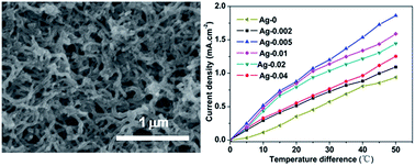
The application of carbon nanotubes (CNTs) as a thermo-electrochemical cell (TEC) electrode is still difficult due to their weak contact with the substrate during the electrophoretic deposition (EPD) method. In this study, by doping the suspension of the CNTs with Mg2+ and Ag powder, Ag–MgO–CNT nanocomposites were successfully prepared on a stainless steel (SS) substrate using the EPD method. The products were confirmed using characterization by scanning electron microscopy, X-ray diffraction, energy-dispersive X-ray and X-ray photoelectron spectroscopy. The TEC performance of the Ag–MgO–CNTs nanocomposite electrodes was significantly improved due to their higher conductivity, thermal conductivity and improved adhesion between the composite film and the SS substrate, depending on the concentrations of the Ag powder. The results suggest that constructing Ag–MgO–CNTs nanocomposite electrodes can effectively enhance the performance of CNTs-based TECs, which might be a promising way for energy harvesting using CNTs-based TECs prepared via the EPD technique.


1 Introduction

To effectively solve the current energy problem, one of the most possible ways is to improve the efficiency of energy conversion by harnessing waste heat. Thermocells, usually called thermo-electrochemical cells (TECs), are the most effective method to convert thermal energy directly to electrical energy. The sustainable energy sources that supply TECs are mainly obtained from waste heat, e.g. waste streams from industry, vehicles exhaust gases, geothermal energy, and data storage systems.1,2

Upon comparison with other solid thermal energy harvesting devices,3–6 TECs become a promising alternatives for harnessing waste heat due to their ease of design, sustained operation, and low cost.1 To make TECs more practical, the electrode materials need to be selected with low cost and relatively high conversation efficiency.1,7 Traditional catalytic materials, such as platinum and palladium, have been used as TEC electrodes because of their high surface catalytic activity in oxidation and reduction reactions.8 However, the high cost and low conversion efficiency have hindered their development. In recent years, carbon nanomaterials have been considered as ideal candidates for TEC electrodes because of their fast electron transfer ability with the potassium ferri/ferrocyanide redox couple.1,2,9–16 However, it is difficult to obtain a high output power and conversation efficiency for carbon nanomaterials composed of a single-component. Nanocomposites can exhibit intriguing properties due to the synergetic effect of their different components, which are beneficial for the practical applications of TECs.7,16 For example, Romano et al. reported that carbon nanotube–reduced graphene oxide composites can achieve a significantly higher conversation efficiency when compared with pristine CNTs due to their faster kinetics and larger electroactive surface area.7 In addition, the composite electrodes have a higher conductivity and specific surface area, which can also result in better properties for the TECs constructed using the composite electrodes.7,16

The electrophoretic deposition (EPD) technique has been widely used to synthesize CNTs-based composites due to its low requirement for the substrate's shape, less time-consuming, large-scale production and low cost.17 Usually, the charging agent, such as Mg(NO3)2, is added into the electrophoretic suspension to improve the adhesion between the CNTs film and the substrate, which is very significant for its practical application.18,19 In addition, the charged ions can bring the CNTs to the anode to form the homogeneous film on the substrate.19,20 However, the existence of Mg2+ decreases the conductivity of the CNTs due to the formation of MgO after the heat treatment step.18,19 Ag–CNTs composites can improve the conductivity and thermal conductivity when compared with pristine CNTs21–23 and CNTs coated with Ag particles have also improved the electrochemical properties of CNTs.24–26

Therefore, doping CNTs with Mg2+ and Ag is expected to provide superior TEC performance in the nanocomposites. In this study, we have attempted to improve the TEC performance of CNTs by doping the electrophoretic suspension of CNTs with Mg2+ and Ag powder. The Ag–MgO–CNTs nanocomposite electrodes were constructed using the EPD method and the nanocomposite electrodes present significantly improved TEC performance when compared with their undoped counterparts, suggesting a promising way for the energy harvesting using CNTs-based TECs prepared via the EPD technique.

2 Experimental

2.1 Synthesis

The Ag–MgO–CNTs nanocomposites were synthesized on a stainless steel (SS) substrate via the EPD method. First, the SS substrates were pretreated with acetone, ethanol and purified water for 20 min. Multi-walled carbon nanotubes (MWNTs, Shenzhen Nanotech Port Co. Ltd) were washed with acetone and filtered with purified water, then sonicated in nitric acid for about 20 hours to obtain carboxylic MWNTs.17 The carboxylic MWNTs, MgCl2 (99.5%, Aladdin, 0.03 g L−1, see SI-1 in ESI) and silver powder (99.9%, Aladdin) were dispersed in ethanol and sonicated for about 1 hour to form a suspension. The SS substrate and the counter electrode were immersed into the suspension. After deposition, the products were subjected to an annealing process in a furnace at 700 °C and the Ag–MgO–CNTs nanocomposites were obtained. The TEC performance of the composites can be optimized by adjusting the concentration of Ag in the suspension. The as-prepared composites were denominated as Ag–MgO–CNTs-x, where x represents the concentration of Ag powder.

2.2 Characterization

The morphology of the products was observed by scanning electron microscopy (SEM; Hitachi S-4800). The species of the products were verified by X-ray diffraction (XRD; GmbH SMART APEX) and composition analysis was performed by energy-dispersive X-ray analysis (EDS) and X-ray photoelectron spectroscopy (XPS; PHI 5000 VersaProbe).

Tensile tests were conducted using an Instron 3343 instrument to evaluate the adhesion between the films (including the pristine CNTs and the Ag–MgO–CNTs nanocomposites) and the SS substrates. First, the sample was fixed with a clamp and subsequently wrapped with the tape. During the test, the tape grabbing film was pulled away until the film peeled off from the SS substrate.

Four tungsten needles (about 50 μm in diameter) were fixed in line at equal distance. The sample was first scraped in part to expose the bare SS substrate for the electrical contact test, then it was placed on the platform in contact with the top four needles, and its position could be adjusted to leave the composites film or the CNTs part between the middle two needles. Current was supplied through the outside two needles, and the voltage can be obtained using the two middle needles.

2.3 TEC testing

The TEC performance of the products, such as the short-circuit current (Isc) and the open-circuit potential (voc), was tested in a U-shaped device. The distance between the two test electrodes was 7 cm and the electrode area was 0.36 cm2. A 0.4 M potassium ferri/ferrocyanide (Aladdin) aqueous solution was used as the electrolyte. The temperatures of the hot and cold sides were controlled using heater tape and a recirculating water chiller, respectively. The temperature readings of the two sides were both measured using OMEGA thermocouple probes. The potential and current were obtained using a KEITHLEY 2440 multimeter.

3 Results and discussion

The typical morphologies of the samples are shown in Fig. 1. From the SEM images (Fig. 1a–f), the pristine CNTs sample, with diameters of 30–50 nm, exhibited entanglements (Fig. 1a). As shown in Fig. 1b and c, the surface morphology of the CNTs did not show any obvious change with a lower concentration of Ag. However, upon increasing the content of Ag (Fig. 1d and e), the surface of the CNTs was covered by agglomerated Ag particles and the surface pastes became more obvious. When the concentration of Ag was increased up to 0.04 g L−1 (Fig. 1f), the surface of the CNTs was almost completely covered by the Ag paste due to the excessive existence of Ag powder, which might result in a decrease in the specific surface area of the CNTs.
image file: c5ra19182c-f1.tif
Fig. 1 SEM images of pristine CNTs and the Ag–MgO–CNTs formed with different concentrations of Ag powder. (a) Pristine CNTs, (b–f) samples obtained by doping 0.002, 0.005, 0.01, 0.02, and 0.04 g L−1 of Ag in the suspension, respectively. Note: the concentration of CNTs and Mg2+ were kept constant at 0.1 and 0.03 g L−1 respectively.

XRD and EDS characterizations were applied to confirm the species and compositions of the products. XRD (Fig. 2a) showed the typical reflection peaks at 26.4°, 38.2° and 64.5°, corresponding to the (002) crystallographic planes of the CNTs27,28 and (111), (220) planes of Ag.22,29 The other four crystallographic planes correspond to SS(110), SS(200), SS(200) and SS(211).30 It is worth mentioning that the reflection peaks of MgO were not observed by XRD, which might be due to the existence of amorphous MgO.31 The EDS result (Fig. 2b) showed the signals for Fe, Cr, C, O, Mg and Ag, as expected. The signals of Fe and Cr are from the stainless steel substrate. The O signal was mainly from MgO due to the heat treatment and MgO can improve the adhesiveness between the composite film and the SS substrate. The Ag signal was from the Ag powder. The results indicate that the products include CNTs and Ag species.


image file: c5ra19182c-f2.tif
Fig. 2 (a) XRD and (b) EDS results of the Ag–MgO–CNTs-0.01 nanocomposite.

Further characterization by XPS showed the expected signals from C, O, Mg and Ag for the nanocomposites, as shown in Fig. 3 (also see the ESI, Fig. S2 and Table S1). For the C 1s spectrum (Fig. 3a), a major peak from the C–C/C[double bond, length as m-dash]C bonds was observed at 284.6 eV. In addition, minor peaks from the C–O and C[double bond, length as m-dash]O bonds were observed at 286.2 and 289.2 eV, respectively.32 As shown in Fig. 3b, the peak from Mg–O bonds was detected at 1303.9 eV for Mg 1s, which was higher than the peak of metallic Mg (Mg 1s at ∼1303 eV).33 For the O 1s spectrum (Fig. 3c), three peaks at 530.1, 531.7 and 533.3 eV were assigned as the O–Mg, O–C and O[double bond, length as m-dash]C bonds, respectively.32,34,35 As shown in Fig. 3d, the binding energies (BE) of the Ag 3d3/2 and 3d5/2 appear at 374.2 eV and 368.2 eV, respectively, corresponding to the BE of the metallic silver.36,37 XPS characterization confirmed the existence of MgO and Ag species in the product.


image file: c5ra19182c-f3.tif
Fig. 3 XPS spectra of the Ag–MgO–CNTs-0.01 sample prepared via EPD. (a) C 1s; (b) Mg 1s; (c) O 1s; and (d) Ag 3d. Note: the peak for C 1s at 284.6 eV was used for calibration.

Tensile tests were conducted to investigate the function of the CNTs-based films on the adhesion between the films and the SS substrate. We performed the tensile tests to measure this adhesion by mechanically pulling away the CNT-based films from the SS substrate (see Experimental section). As shown in Fig. 4a, the stress curve for the pristine CNTs shows a maximum stress of 0.26 MPa, when doped with Ag powder, the maximum stress of the nanocomposites increased up to 0.32, 0.97, 0.67, 0.62 and 0.48 MPa, corresponding to Ag contents of 0.002, 0.005, 0.01, 0.02 and 0.04 g L−1, respectively, showing clearly the adhesion enhancement with the existence of Ag. Usually, CNTs prepared by EPD have high electrical resistance due to the weak contact between the CNTs film and SS substrate.38 In our experiment, the Mg2+ and Ag powder were added in the CNTs suspension to decrease the electrical resistance of the CNTs electrode. A four-probe device (see Experimental section) was applied to study the electrical resistance of the pristine CNTs and the Ag–MgO–CNTs nanocomposites. As shown in Fig. 4b, the resistance of the pristine CNTs electrode was measured to be 80.2 Ω, whereas the resistance of Ag–MgO–CNTs nanocomposite electrodes was measured to be 57.9, 10.0, 19.9, 29.8 and 39.2 Ω, corresponding to Ag concentrations of 0.002, 0.005, 0.01, 0.02 and 0.04 g L−1. The results indicate that the surface resistance of the CNTs electrode can be enhanced with the existence of Ag, in agreement with the results of the tensile tests. The resistance of Ag-0.005 was smaller than Ag-0.01, Ag-0.02 and Ag-0.04, mainly due to two reasons as follows. First, the adhesion of the Ag-0.005 sample shows the largest value when compared with the other samples (see Fig. 4a), indicating the good surface contact between the Ag-0.005 sample and the SS substrate. Second, the existence of excessive Ag leads to the agglomeration of the Ag particles in the samples (see Fig. 1d–f), which may not be beneficial for the improvement of the conductivity due to the weak synergetic effect of the CNTs-based nanocomposites.


image file: c5ra19182c-f4.tif
Fig. 4 (a) Tensile tests and (b) four-probe current–voltage measurements of the pristine CNTs and the Ag–MgO–CNTs nanocomposites.

If TECs are continuously operated in an open environment for a long time, the concentration of the electrolyte would be changed due to evaporation of the solution, resulting in the instability of the TEC performance. However, TECs in a closed system can operate with long-term stability.1 In this study, the U-shaped TECs (Fig. 5a) in a closed system were applied to investigate the TEC performance. As shown in Fig. 5b, the open circuit voltage (voc) and the temperature difference (ΔT) show a linear relationship.


image file: c5ra19182c-f5.tif
Fig. 5 (a) The U-shaped setup for the TEC performance measurements, (b) Seebeck coefficient measurements for the 0.4 M ferro/ferricyanide redox couple, (c) Jsc versus temperature difference between the two test electrodes and (d) Pmax versus temperature difference.

The Seebeck coefficient of the redox couple was usually employed using 0.4 M potassium ferro/ferricyanide due to its high Seebeck coefficient and large exchange current.1,7 By linear fitting the data, the Seebeck coefficient was obtained as ∼1.42 mV K−1, in agreement with the literature.1,15 Fig. 5c shows that the current densities (Jsc) improved upon increasing the temperature difference for the pristine CNTs and the nanocomposites, and the Jsc of the Ag–MgO–CNTs composite electrodes were much higher than that found for the pristine CNTs electrode at the same temperature difference, which contributed to the better conductivity, thermal conductivity, and adhesion between the composite films and the substrate. As for the Ag–MgO–CNTs nanocomposite electrodes, the Ag–MgO–CNT-0.005 nanocomposite shows the best TEC performance, which might be due to the better conductivity, adhesion between the film and the SS substrate, and the higher specific surface area. When the temperature difference climbed to 50 °C, the Jsc and JscT reached 9.4 A m−2 and 0.19 A m−2 K−1 for the CNTs electrode, as well as 18.6 A m−2 and 0.37 A m−2 K−1 for Ag–MgO–CNTs-0.005 composite electrode, respectively.

To evaluate the performance of the TECs, the maximum output power (Pmax) and the relative power conversion efficiency (ηr) are two important parameters. Pmax can be described as 0.25voc × Isc. ηr can be expressed as ηr = η/(ΔT/Th).1,13

image file: c5ra19182c-t1.tif
where A is the cross-sectional area of the electrodes, k represents the thermal conductivity of the redox couple, ΔT and d are the temperature difference and the distance between the test electrodes, respectively, η is the power conversion efficiency and Th is the temperature of the hot side. The Pmax value improves upon increasing the temperature difference from 5 to 50 °C (Fig. 5d). The Pmax and ηr values for the Ag–MgO–CNT-0.005 electrode are 12.06 μW and 0.6%, respectively, 100% higher than that found for the CNTs electrode, contributed to the better conductivity and lower thermal resistance at the electrode/substrate junction.1,7 When compared with other nanocomposite electrodes, such as carbon nanotube–reduced graphene oxide (CNTs–rGO) and carbon nanotube-activated carbon textiles (C-ACT) (see the ESI, Table S2),7,16 the TEC performance of Ag–MgO–CNTs-0.005 was not very excellent due to the high thermal resistance of the CNTs electrode. To achieve optimized output energy from the CNTs-based TEC, the temperature loss between the CNTs electrodes should be considered.1 To solve this problem, one of the most effective ways is to minimize the thermal resistance of the CNTs electrodes. In our experiment, the thermal resistance at the MWNTs film/substrate junction was 0.0611 cm2 K W−1 with a CNTs electrode thickness of 500 μm, which was higher than that previously reported.1,39 Further research should be devoted to improving the performance of the CNTs-based TEC by decreasing the thermal resistance of the junction, e.g. try to improve the thermal conductivity of the junction by reducing the electrodes thickness or selecting single wall CNTs as the electrode.1,40 In addition, taking into account the low ηr of the CNTs-based TEC, it is necessary to design series or flowing TECs.1,11

4 Conclusions

In summary, Ag–MgO–CNTs nanocomposites have been successfully prepared using the EPD method and have been confirmed by different characterization methods. The TEC performance of the Ag–MgO–CNTs nanocomposite electrodes shows significant improvement due to the higher conductivity, thermal conductivity and better adhesion between the composite films and the SS substrate, depending on the concentrations of the Ag powder added. The results indicate that constructing Ag–MgO–CNTs nanocomposite electrodes can effectively improve the TEC performance of CNTs, which might offer a promising way for promoting energy harvesting using CNTs-based TECs prepared via the EPD technique.

Acknowledgements

This study was financially supported by the National Science Foundation of China (No. 11274244, 51302193).

Notes and references

  1. R. C. Hu, B. A. Cola, N. Haram, J. N. Barisci, S. Lee, S. Stoughton, G. Wallace, C. Too, M. Thomas, A. Gestos, M. E. D. Cruz, J. P. Ferraris, A. A. Zakhidov and R. H. Baughman, Nano Lett., 2010, 10, 838–846 CrossRef CAS PubMed.
  2. T. J. Kang, S. L. Fang, M. E. Kozlov, C. S. Haines, N. Li, Y. H. Kim, Y. S. Chen and R. H. Baughman, Adv. Funct. Mater., 2012, 22, 477–489 CrossRef CAS.
  3. C. B. Vining, Nat. Mater., 2009, 8, 83 CrossRef CAS PubMed.
  4. T. Mancini, P. Heller and B. J. Butler, J. Sol. Energy Eng., 2003, 125, 135 CrossRef.
  5. M. Ujihara, G. P. Carman and D. G. Lee, Appl. Phys. Lett., 2007, 91, 093508 CrossRef.
  6. D. A. W. Barton, S. G. Burrow and L. R. Clare, J. Vib. Acoust., 2010, 132, 021009 CrossRef.
  7. M. S. Romano, N. Li, D. Antiohos, J. M. Razal, A. Nattestad, S. Beirne, S. L. Fang, Y. S. Chen, R. Jalili, G. G. Wallace, R. Baughman and J. Chen, Adv. Mater., 2013, 25, 6602–6606 CrossRef CAS PubMed.
  8. T. I. Quickenden and Y. Mua, J. Electrochem. Soc., 1995, 142, 3985 CrossRef CAS.
  9. T. J. Abraham, D. R. MacFarlane and J. M. Pringle, Chem. Commun., 2011, 47, 6260 RSC.
  10. T. J. Abraham, N. Tachikawa, D. R. MacFarlane and J. M. Pringle, Phys. Chem. Chem. Phys., 2014, 16, 2527 RSC.
  11. P. F. Salazar, S. Kumar and B. A. Cola, J. Appl. Electrochem., 2014, 44, 325–336 CrossRef CAS.
  12. T. J. Abraham, D. R. MacFarlane and J. M. Pringle, J. Chem. Phys., 2011, 134, 114513 CrossRef PubMed.
  13. S. Manda, A. Saini, S. Khaleeq, R. Patal, B. Usmani, S. Harinipriya, B. Pratiher and B. Roy, J. Mater. Res. Technol., 2013, 2, 165–181 CrossRef CAS.
  14. M. F. El-Kady, V. Strong, S. Dubin and R. B. Kaner, Science, 2012, 335, 1326 CrossRef CAS PubMed.
  15. L. Tang, Y. Wang, Y. Li, H. Feng, J. Lu and J. Li, Adv. Funct. Mater., 2009, 19, 2782 CrossRef CAS.
  16. H. Im, H. G. Moon, J. S. Lee, I. Y. Chung, T. J. Kang and Y. H. Kim, Nano Res., 2014, 7, 443–452 CrossRef CAS.
  17. A. R. Boccaccini, J. Cho, J. A. Roether, B. J. C. Thomas, E. J. Minay and M. S. P. Shaffer, Carbon, 2006, 44, 3149–3160 CrossRef CAS.
  18. A. A. Talin, K. A. Dean, S. M. O'Rourke, B. F. Coll, M. Stainer and R. Subrahmanyan, US Pat., 6902658, 2005.
  19. S. Oh, J. Zhang, Y. Cheng, H. Shimoda and O. Zhou, Appl. Phys. Lett., 2004, 84, 3738–3740 CrossRef CAS.
  20. H. Zhao, H. Song, Z. Li, G. Yuan and Y. Jin, Appl. Surf. Sci., 2005, 251, 242–244 CrossRef CAS.
  21. L. F. Chen, H. Q. Xie and W. Yu, J. Mater. Sci., 2012, 4, 5590–5595 CrossRef.
  22. R. X. Dong, C. T. Liu, K. C. Huang, W. Y. Chiu, K. C. Ho and J. J. Lin, ACS Appl. Mater. Interfaces, 2012, 4, 1449–1455 CAS.
  23. F. Xin and L. Li, Composites, Part A, 2011, 42, 961–967 CrossRef.
  24. P. Yang, W. Wei, C. Tao, B. Xie and X. Chen, Microchim. Acta, 2008, 162, 51 CrossRef CAS.
  25. G. Y. Gao, D. J. Guo, C. Wang and H. L. Li, Electrochem. Commun., 2007, 9, 1582–1586 CrossRef CAS.
  26. D. J. Guo and H. L. Li, Carbon, 2005, 43, 1259–1264 CrossRef CAS.
  27. N. Jha and S. Ramaprabhu, J. Appl. Phys., 2009, 106, 084317 CrossRef.
  28. H. K. Kim, K. C. Roh, K. Kang and K. B. Kim, RSC Adv., 2013, 3, 14267–14272 RSC.
  29. R. Mendoza-Résendez, A. Gómez-Treviño, E. D. Barriga-Castro, N. O. Núnez and C. Luna, RSC Adv., 2014, 4, 1650–1658 RSC.
  30. A. K. de, D. C. Murdock, M. C. Mataya, J. G. Speer and D. K. Matlock, Scr. Mater., 2004, 50, 1445–1449 CrossRef CAS.
  31. S. K. Mahadeva, J. C. Fan, A. Biswas, K. S. Sreelatha, L. Belova and K. V. Rao, Nanomaterials, 2013, 3, 486–497 CrossRef CAS.
  32. T. I. T. Okpalugo, P. Papakonstantinou, H. Murphy, J. McLaughlin and N. M. D. Brown, Carbon, 2005, 43, 153–161 CrossRef CAS.
  33. J. S. Corneille, J. W. He and D. W. Goodman, Surf. Sci., 1994, 36, 269–278 CrossRef.
  34. X. B. Yan, T. Xu, S. R. Yang, H. W. Liu and Q. J. Xue, J. Phys. D: Appl. Phys., 2004, 37, 2416–2424 CrossRef CAS.
  35. G. Carta, N. E. Habra, L. Crociani, G. Rossetto, P. Zanella, A. Zanella, G. Paolucci, D. Barreca and E. Tondello, Chem. Vap. Deposition, 2007, 13, 185–189 CrossRef CAS.
  36. G. A. Gelves, B. Lin, U. Sundararaj and J. A. Haber, Adv. Funct. Mater., 2006, 16, 2423–2430 CrossRef CAS.
  37. S. H. Lee, C. C. Teng, C. M. Ma and I. Wang, J. Colloid Interface Sci., 2011, 364, 1–9 CrossRef CAS PubMed.
  38. Y. R. Chen, H. Jiang, D. B. Li, H. Song, Z. M. Li, X. J. Sun, G. Q. Miao and H. F. Zhao, Nanoscale Res. Lett., 2011, 6, 537 CrossRef PubMed.
  39. B. A. Cola, J. Xu, C. Cheng, X. Xu, H. Hu and T. S. Fisher, J. Appl. Phys., 2007, 101, 054313 CrossRef.
  40. M. Fujii, X. Zhang, H. Q. Xie, H. Ago, K. Takahashi, T. Ikuta, H. Abe and T. Shimizu, Phys. Rev. Lett., 2005, 95, 065502 CrossRef PubMed.

Footnote

Electronic supplementary information (ESI) available. See DOI: 10.1039/c5ra19182c

This journal is © The Royal Society of Chemistry 2015
Click here to see how this site uses Cookies. View our privacy policy here.