
Improved mechanical and tribological properties of bismaleimide composites by surface-functionalized reduced graphene oxide and MoS2 coated with cyclotriphosphazene polymer
Zhengyan Chen,
Hongxia Yan*,
Tianye Liu,
Song Niu and
Jiayi Ma
Department of Applied Chemistry, School of Science, Northwestern Polytechnical University, Xi’an, Shaanxi 710129, China. E-mail: hongxiayan@nwpu.edu.cn; Fax: +86 29 88431657
First published on 3rd November 2015
Abstract
Surface-functionalized reduced graphene oxide and MoS2 hybrid nanosheets (rGO/MoS2) were obtained with a poly-(cyclotriphosphazene-co-4,4′-diaminodiphenylmethane) (PZD) polymer coating by a one-pot noncovalent method. The PZD/rGO/MoS2 hybrid nanoparticles were then chosen as fillers to improve the mechanical and tribological properties of bismaleimide (BMI) resin. The results showed that suitable addition of PZD/rGO/MoS2 could greatly enhance not only the mechanical and tribological properties but also the thermal stability. A low friction coefficient of 0.06 and volume wear rate of 1.80 × 10⁻⁶ mm3 (N m)−1 with 0.4 wt% PZD/rGO/MoS2 were obtained. This is mainly attributed to the unique layered structure of PZD/rGO/MoS2 hybrid nanoparticles, the enhanced toughness of the composites, good interfacial adhesion and compatibility between PZD/rGO/MoS2 and the BMI matrix, as well as the synergistic effect between nanosheets of rGO and MoS2.
1 Introduction
Bismaleimide (BMI) is a leading class of thermosetting polyimides based on low molecular weight building blocks and terminated by reactive groups which undergo polymerization by thermal or catalytic means.1 It is a material widely used in some of the most important areas, ranging from military programs, such as the Air Force, to electronic engineering.2,3 However, the cured resin is extremely brittle because of its high cross-link density, resulting in its poor mechanical property and friction performance. Therefore, it has been a hot point of research to modify and increase the friction performance of BMI resins.As is well known, lubrication is one of the most effective approaches to reduce friction and wear in engineering.4,5 Two-dimensional graphene nanosheets and graphene-based materials have attracted significant attention in recent years due to their excellent material properties.6–9 Owing to the unique structure of graphene, it has excellent thermal, electrical and beneficial mechanical properties.10–12 Especially, the graphene surface, formed by sp2 bonded carbon atoms, is atomically flat and free of dangling bonds, which makes it an ideal starting template for other 2D materials.13 In recent years, graphene and modified graphene have attracted increasing interest as fillers for polymer nanocomposites in base-lubricant materials, such as poly(vinyl chloride), polyimide and BMI resin, to improve their friction and wear properties.14,15 Wang et al.16 prepared multi-layer graphene filled poly(vinyl chloride) composites and discovered that the presence of multi-layer graphene could greatly decrease the friction coefficient and wear rate of the composites. Min et al.17 synthesized graphene oxide/polyimide nanocomposites using in situ polymerization and found that the composites exhibited better tribological properties under seawater-lubricated conditions.
Recently, the versatility and success of graphene have also led many researchers to investigate other two-dimensional nanomaterials, among which more attention has been paid to the typical layered transition metal dichalcogenides, in particular, MeX2 (Me = Mo, W, Nb; X = S, Se, Te),18,19 which have an analogous structure to graphene. In particular, MoS2 is a typical layered transition metal sulfide composed of three layers: a Mo layer sandwiched between S bilayers, in which each layer consists of a covalently bonded S–Mo–S hexagonal quasi-two-dimensional network, with weak van der Waals stacking between the layers.20–22 MoS2 has been particularly important for solid lubrication or as an additive as “the king of lubrication” for a long time. It is well known that nanosized MoS2 usually has better tribological properties, either in friction reduction or wear resistance, than microsized and bulk MoS2.23
Since both MeX2 and graphene have a similar microstructure and morphology, heterolayered graphene/MeX2 composites, which maximize structural compatibility, may synergize the MeX2 nanosheets and graphene interaction, resulting in favorable outcomes greater than the sum of the individual components.24–27 Therefore, significant efforts have been turned to fabricate graphene/MeX2 composites. Yao et al.28 prepared a sample of multilayer graphene and WS2, which exhibited a lower friction coefficient and wear rate; Li et al.29 developed a facile and effective hydrothermal method to prepare MoSe2 nano-flowers on reduced graphene oxide sheets, and the composites as additives showed good friction and wear properties. However, to our knowledge, there is no literature so far investigating graphene/MoS2 hybrid nanoparticles as fillers in the application of friction resin matrix composites.
Polyphosphazenes are a versatile class of hybrid organic–inorganic materials possessing a backbone of alternating nitrogen and phosphorous atoms with remarkable properties and multiple applications.30,31 Surface functionalization of conventional fillers using polyphosphazenes has been carried out to modify the resins to improve the interfacial properties of composites.32 In this study, a simple noncovalent side-wall functionalization of rGO/MoS2 hybrids using poly-(cyclotriphosphazene-co-4,4′-diaminodiphenylmethane) (PZD) is reported. Subsequently, the PZD/rGO/MoS2 hybrid nanoparticles were added as a solid lubricant and curing agent in BMI resin to fabricate PZD/rGO/MoS2/BMI composites by a casting method (Fig. 1). The as-fabricated composites exhibited excellent mechanical and tribological properties, as well as thermal stability.
 | ||
| Fig. 1 The synthesis route of PZD functionalized rGO/MoS2. | ||
2 Material and methods
2.1. Reagents and materials
MoS2 (99%, particle size < 2 μm, #234842 Sigma-Aldrich) and NaCl (≥99.5%, #S7653 Sigma-Aldrich) were used as received. Natural graphite flakes (325 mesh) were obtained from Qingdao Hensen Graphite Co., Ltd. The graphene oxide (GO) nanosheets were produced from natural graphite flakes by a modified Hummers method.33 Hexachlorotriphosphazene (HCCP), 4,4′-diaminodiphenylmethane (DDM) and triethylamine (TEA) were purchased from Aladdin Chemistry Co., Ltd. N-Methylpyrrolidone (NMP), ethanol, tetrahydrofuran (THF), ammonia water and hydrazine hydrate were purchased from Tianjin Tianli Chemical Reagents Co. Ltd. The BMI was provided by the Rongchang Ning research group at Northwestern Polytechnical University. Diallyl Bisphenol A (DBA) and 4,4′-bismaleimidodiphenylmethane (BDM) were purchased from Sigma-Aldrich. All reagents were of analytical grade and used as received without further purification.2.2. Experimental section
![[thin space (1/6-em)]](https://www.rsc.org/images/entities/char_2009.gif) :7, grinding for 2 h with a rotation rate of 560 rpm. The obtained solid mixture was thoroughly washed several times using deionized water to remove NaCl, and then dried under vacuum at 60 °C for 8 h to obtain the exfoliated MoS2 nanosheets (exf-MoS2). Then, 0.2 g of exf-MoS2 nanosheets and 0.4 g of GO were dissolved in NMP and dispersed with ultrasound disintegration. Subsequently, the mixture was transferred to a 250 mL three-mouth flask containing a mechanical stirrer and was vigorously stirred at 25 °C for 2 days. Then, two drops of concentrated hydrochloric acid were added to the reaction mixture, which was stirred in the sealed flask for 1 day at 80 °C. The black product was collected by centrifugation with deionized water and absolute ethanol three times, freeze-dried for further reaction, and labelled as GO/MoS2.
:7, grinding for 2 h with a rotation rate of 560 rpm. The obtained solid mixture was thoroughly washed several times using deionized water to remove NaCl, and then dried under vacuum at 60 °C for 8 h to obtain the exfoliated MoS2 nanosheets (exf-MoS2). Then, 0.2 g of exf-MoS2 nanosheets and 0.4 g of GO were dissolved in NMP and dispersed with ultrasound disintegration. Subsequently, the mixture was transferred to a 250 mL three-mouth flask containing a mechanical stirrer and was vigorously stirred at 25 °C for 2 days. Then, two drops of concentrated hydrochloric acid were added to the reaction mixture, which was stirred in the sealed flask for 1 day at 80 °C. The black product was collected by centrifugation with deionized water and absolute ethanol three times, freeze-dried for further reaction, and labelled as GO/MoS2.Then, the obtained GO/MoS2 was dispersed in 180 mL of distilled water through ultrasonication for 30 min. Subsequently, the mixture was transferred to a 250 mL three-mouth flask containing a mechanical stirrer and a reflux-condenser, adding in 2.5 mL of hydrazine hydrate and 7.5 mL of ammonia water, and was heated to 98 °C for 6 h. After the reaction, the resulting product, abbreviated as rGO/MoS2, was filtered and washed with distilled water and ethanol several times, and then dried under vacuum at 60 °C for 12 h.
:4 were heated to 140 °C in a glass beaker and kept at this temperature until totally melted. Then a suitable amount of rGO/MoS2 was added into the melted BMI resin and stirred for about 30 min to disperse uniformly. Subsequently, the mixture was put into a pre-heated mold with release agent, followed by degassing at 150 °C for about 1 h in a vacuum oven. After that, the mixture was cured following the schedule of 150 °C/2 h + 180 °C/2 h + 220 °C/4 h. The post curing process was 250 °C/4 h. Finally, the mold was cooled to room temperature and demolded to get the samples of PZD/rGO/MoS2/BMI composites.2.3. Characterization
The X-ray diffraction (XRD) patterns of the samples were recorded on a Bruker D8 ADVANCE X-ray diffractometer with Cu Kα radiation (λ = 0.15405 nm). The 2θ angular regions between 5° and 85° were investigated with a scanning rate of 0.02° s−1. High resolution transmission electron microscopy (HRTEM) images were obtained with a JEOL JEM-200CX microscope operating at 200 kV. X-ray photo-electron spectroscopy (XPS, Thermal Scientific K-Alpha XPS spectrometer) was used to investigate the surface elemental composition of the as-prepared samples. The analysis was performed under a 1027 Torr vacuum with an AlKα X-ray source with a power of 200 W. Fourier transform infrared (FT-IR) spectra of the samples were recorded between 400 and 4000 cm−1 with a resolution of 2 cm−1 on a Nicolet FT-IR 5700 spectrometer (USA). Scanning electron micrographs (SEM) were obtained on a HITACHIS-570 instrument. Raman spectra were recorded on a Renishaw Invia Plus Raman microscope using a 633 nm argon ion laser.Impact strength was determined according to GB/T 2571-1995. Samples were cut into strips of (80 ± 0.2) × (10 ± 0.2) × (4 ± 0.2) mm3 by a cutting machine. Flexural strength was measured according to GB/T 2570-1995. Samples were cut into strips of (80 ± 0.2) × (15 ± 0.2) × (4 ± 0.2) mm3. The friction and wear tests were performed according to GB 3960-83 (Chinese Standard) on a test machine (M-200, load 196 N, rotation speed 200 rpm) under dry-sliding conditions. The thermal gravimetric analysis (TGA) tests were performed by using a Perkin Elmer TGA-7 (USA) at a heating rate of 10 °C min−1 in an argon atmosphere from 50 to 800 °C.
3 Results and discussion
Fig. 2 shows the XRD patterns of bulk MoS2, exf-MoS2 and rGO/MoS2 nanoparticles. All of the sharp diffraction peaks of bulk MoS2 can be attributed to the hexagonal phase (JCPDS no. 37-1492). The strong (002) peak with a d-spacing of 0.62 nm signifies a well-stacked layered structure along the c axis.35 After exfoliation, both restacked MoS2 and rGO/MoS2 show a much shorter (002) peak, indicating a decrease of crystallite size and the number of layers along the c axis.36 It is noteworthy that the peaks of the exf-MoS2 and MoS2/rGO hybrids shift greatly to the left, both appearing at 12.35°. According to the Bragg equation, the distance for d (002) of MoS2 in the exf-MoS2 and MoS2/rGO hybrids was calculated to be 0.71 nm. Additionally, the rGO/MoS2 nanoparticles still retain the position of the diffraction peaks of MoS2, and the new diffraction peak of rGO at 2θ ≈ 24° can be detected. The XRD results imply that the interlayer distance of MoS2 is enlarged after the exfoliation process, and that the thickness of MoS2 layers can be further reduced in rGO/MoS2 hybrids due to the presence of rGO.37 | ||
| Fig. 2 (a) XRD patterns of bulk MoS2, exf-MoS2 and rGO/MoS2 nanoparticles; (b) magnified XRD pattern of the rGO/MoS2 nanoparticles. | ||
In order to investigate the rGO/MoS2 and PZD functionalization of rGO/MoS2, XPS was employed. Fig. 3a shows the survey spectra of rGO/MoS2 and PZD/rGO/MoS2. In the XPS spectrum of rGO/MoS2, three obvious peaks are observed at 286.0, 399.1 and 532.1 eV, corresponding to C 1s, N 1s and O 1s, respectively. Moreover, the binding energy of 229.2 and 162.8 eV, which is ascribed to Mo 3d and S 2p, respectively, is observed. These results mentioned above indicate that rGO/MoS2 is synthesized successfully. Compared to the rGO/MoS2 spectrum, the XPS spectrum of PZD/rGO/MoS2 shows a significant amount of C 1s, which is ascribed to the 4,4′-diaminodiphenylmethane coating. In addition, new peaks at 129.7, 190.9 and 200.0 eV correspond to P 2p, P 2s and Cl 2p, respectively, which are attributed to the hexachlorotriphosphazene coating. The XPS spectrum of PZD/rGO/MoS2 indicates that rGO/MoS2 has been successfully functionalized with the cyclotriphosphazene polymer containing phosphorus and nitrogen.
 | ||
| Fig. 3 XPS spectra of (a) rGO/MoS2 and PZD/rGO/MoS2; (b) C 1s; (c) Mo 3d; (d) S 2p; (e) P 2p of PZD/rGO/MoS2. | ||
In detail, the C 1s XPS peak-fitting (Fig. 3b) shows four peaks at 284.5, 285.1, 285.9 and 287.5 eV, which correspond to an sp2-hybridized C![[double bond, length as m-dash]](https://www.rsc.org/images/entities/char_e001.gif) C double bond, sp3-hybridized C–C single bond, carbon in a C–O single bond and carbon in a CO double bond, respectively. There are two doublets of Mo-3d signals (Fig. 3c), the peaks of Mo 3d5/2 and Mo 3d3/2 with binding energies of 229.2 and 232.4 eV, respectively, are assigned to MoS2. Meanwhile a small S 2s peak is located at a slightly lower binding energy of 226.4 eV (Fig. 3d). And the binding energies of 162.1 and 163.2 eV correspond to S 2p3/2 and S 2p1/2, respectively. Additionally, in Fig. 3e, the peaks attributed to the binding energy for the P–Cl bond, PN bond and P–N–C bond are observed at 132.98, 133.7 and 133.9 eV, respectively. The XPS spectra indicate that the cyclotriphosphazene-co-4,4′-diaminodiphenylmethane polymer has been successfully coated onto the rGO/MoS2 surface.
C double bond, sp3-hybridized C–C single bond, carbon in a C–O single bond and carbon in a CO double bond, respectively. There are two doublets of Mo-3d signals (Fig. 3c), the peaks of Mo 3d5/2 and Mo 3d3/2 with binding energies of 229.2 and 232.4 eV, respectively, are assigned to MoS2. Meanwhile a small S 2s peak is located at a slightly lower binding energy of 226.4 eV (Fig. 3d). And the binding energies of 162.1 and 163.2 eV correspond to S 2p3/2 and S 2p1/2, respectively. Additionally, in Fig. 3e, the peaks attributed to the binding energy for the P–Cl bond, PN bond and P–N–C bond are observed at 132.98, 133.7 and 133.9 eV, respectively. The XPS spectra indicate that the cyclotriphosphazene-co-4,4′-diaminodiphenylmethane polymer has been successfully coated onto the rGO/MoS2 surface.
FT-IR spectra of the as-prepared GO and PZD/rGO/MoS2 nanoparticles are displayed in Fig. 4a. The characteristic peaks of GO appear at 3442, 1643 and 1040 cm−1, which are ascribed to –OH, CC and C–O vibrations, respectively. Furthermore, the peak of PZD/rGO/MoS2 at 1643 cm−1 corresponds to CC vibrations, indicating the reduction of GO. By contrast, after coating the cyclotriphosphazene polymer on the surface of rGO/MoS2, the characteristic peaks at 1554 and 1380 cm−1, which are attributed to the N–H bending vibration and the C–N stretching vibration of (Ph)–NH or (Ph)–NH2, respectively, are observed.38 The above signals are ascribed to DDM units. Meanwhile, the new peaks at 1173, 998, 900 and 610 cm−1 are attributed to the asymmetric stretching vibration of the PN and the P–N groups of the cyclophosphazene ring, to the P–N stretching vibration of the new P–NH–(Ph) band, and to the P–Cl absorption of the cyclophosphazene ring,39 respectively. These results also provide evidence of successfully coating the cyclotriphosphazene polymer onto the surface of rGO/MoS2.
 | ||
| Fig. 4 (a) FT-IR spectra of as-prepared GO and PZD/rGO/MoS2 nanoparticles; (b) Raman spectra of GO, bulk MoS2 and rGO/MoS2. | ||
Raman spectroscopy is applied to investigate the different microstructures of the as-prepared GO, bulk MoS2 and rGO/MoS2. As shown in Fig. 4b, the two dominant peaks of pristine MoS2 at 376 and 403 cm−1 correspond to the E12g and A1g modes of the hexagonal MoS2, respectively.40 The E12g mode accords with the in-layer displacement of Mo and S atoms, while the A1g mode involves the out-layer symmetric displacement of S atoms along the c axis.41 Besides the predominant MoS2 peaks, two other Raman peaks at 1349 and 1596 cm−1, which are attributed to the D and G bands of rGO, can be detected in rGO/MoS2. The D band is ascribed to the disorder and defects of rGO, while the G band is attributed to the vibration of sp2 carbon atoms. The relative intensity ratio ID/IG of GO is calculated to be 0.82, while the ID/IG in the rGO/MoS2 sample is calculated to be 1.19. The calculated ID/IG value of the rGO/MoS2 nanoparticles has greatly increased compared to that of GO, which is attributed to the reduction of GO.
To better understand the microstructure and morphology of the rGO/MoS2 and PZD/rGO/MoS2 nanoparticles, we performed TEM and HRTEM. It can be clearly seen that bulk MoS2 (Fig. 5a) displays a perfect layered structure with the d(002) = 0.62 nm, which is consistent with the XRD analysis for the hexagonal lattice of the MoS2 phase. And after hybridization, as labeled in Fig. 5b and c, the rGO/MoS2 hybrids are well fabricated layer-by-layer, the exf-MoS2 is well dispersed in the rGO, and the interlayer distance of the rGO/MoS2 hybrids is 0.71 nm, much larger than that of bulk MoS2, which is consistent with the XRD results. Compared to the rGO/MoS2 hybrids, some grey sheets on the surface of the PZD/rGO/MoS2 nanoparticles are observed in Fig. 5d, which can be attributed to the cyclotriphosphazene polymer coated onto the surface of rGO/MoS2.
 | ||
| Fig. 5 TEM (b and d) and HRTEM (a and c) images, (a) bulk MoS2; (b and c) rGO/MoS2; (d) PZD/rGO/MoS2 nanoparticles. | ||
The dependency of the impact and flexural strength of the PZD/rGO/MoS2/BMI composites on the content of PZD/rGO/MoS2 is shown in Fig. 6a and b. It can be clearly seen that the appropriate amount of PZD/rGO/MoS2 can properly improve the impact and flexural strength of the neat BMI resin. The impact and flexural strength increase continuously with the addition of PZD/rGO/MoS2, which reach the maximum values of 15.98 kJ m−2 and 179.32 MPa with 0.6 wt% fillers, increased by 21.52% and 32.12% in comparison to those of the neat BMI resin (the impact and flexural strength of the neat BMI resin are 13.15 kJ m−2 and 135.72 MPa, respectively). This is mainly ascribed to the following reasons: (1) there is a synergistic effect between the exf-MoS2 and rGO, in addition, polyphosphazene is a kind of inorganic–organic polymer which can improve the compatibility with BMI resin, thus the unique structure of PZD/rGO/MoS2 hybrids can increase dispersibility in the BMI matrix, the improved dispersibility is the most important factor for affecting the impact and flexural strength of the composites;42 (2) –NH2 groups in PZD/rGO/MoS2 can react with carbon–carbon double bonds of the BMI resin, resulting in an improved interfacial bonding strength between PZD/rGO/MoS2 and the resin matrix.43 However, when the content of fillers exceeds 0.6 wt%, the impact and flexural strength of the composites decrease and are even lower than those of the neat BMI resin. This phenomenon can be explained in that excessive PZD/rGO/MoS2 hybrid nanoparticles can agglomerate in the matrix, therefore, the advantages of PZD/rGO/MoS2 are not fully realized.44
 | ||
| Fig. 6 Impact strength (a) and flexural strength (b) of composites with different PZD/rGO/MoS2 content. | ||
In order to further confirm the effect of PZD/rGO/MoS2 on the toughness of the BMI resin, SEM images of the fracture surfaces of the neat BMI resin and PZD/rGO/MoS2/BMI composites taken from impact tests are shown in Fig. 7a and b. The fracture surface of the neat BMI resin is slick, exhibiting a typical brittle feature. While with the addition of 0.6 wt% PZD/rGO/MoS2 into the BMI resin, the fracture surface of the composite is indented and a large amount of ductile sunken areas exist, exhibiting a typical rough feature, which can absorb large amounts of energy of fracture and put off the micro-crack propagation. In addition, we can clearly see that there are no obvious aggregates on the fracture surface of the 0.6 wt% PZD/rGO/MoS2/BMI composite, indicating that PZD/rGO/MoS2 fillers are well compatible with the BMI resin matrix in appropriate amounts. The features of the fracture surfaces of the composites are consistent with the improved impact strength of the composites.
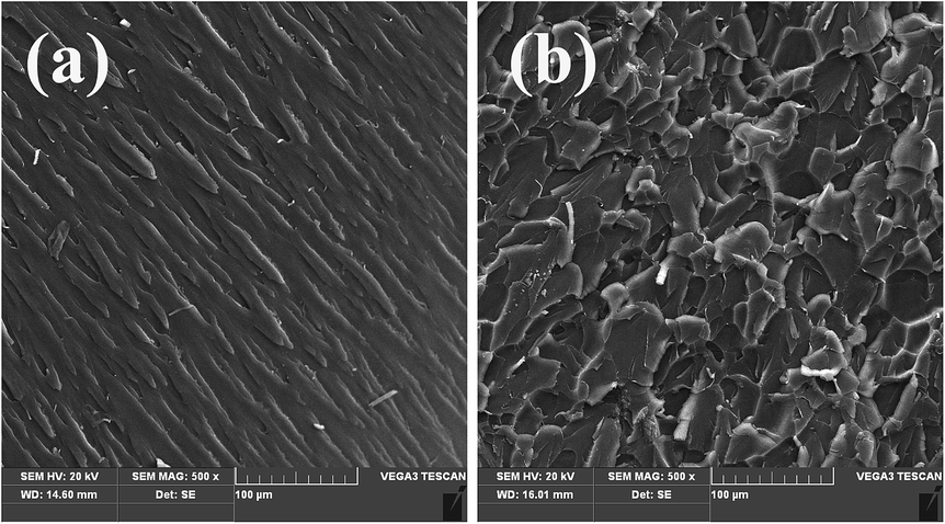 | ||
| Fig. 7 SEM images of the fracture surfaces of (a) the neat BMI and (b) the composite with 0.6 wt% PZD/rGO/MoS2. | ||
Fig. 8a shows the change curves of friction coefficients of the PZD/rGO/MoS2/BMI composites as a function of PZD/rGO/MoS2 content for the steady-state sliding against a steel counterpart under dry conditions. It can be clearly seen that the neat BMI resin and the PZD/rGO/MoS2/BMI composites all have a high friction coefficient in the initial stage of friction, which is attributed to the fact that the real contact area between the rigid friction pairs and the composites is relatively small, and the composites showed plastic deformation under shear stress during the dry-sliding friction, resulting in a rapid increase of the friction coefficient. Over time, the friction coefficient values of the PZD/rGO/MoS2/BMI composites decrease more sharply when the PZD/rGO/MoS2 content is below 0.8 wt% (the friction coefficient is as low as about 0.06), which is mainly attributed to the fact that the PZD/rGO/MoS2/BMI composites are easier to deform under tangential stress than the neat BMI resin. On the other hand, a dense transfer film is formed on the surface of the steel counterpart, providing a low-strength junction at the interface and making the friction mainly occur between the composites and the transfer film, resulting in lower friction coefficients of the composites. However, with a further increase of the concentration, the friction coefficient has increased a little but is still much lower than that of the neat BMI resin, which is attributed to45 the excessive PZD/rGO/MoS2 agglomerates of BMI resin in the contact zone, which create more microcracks in the composites under high load, thus the load-carrying capability of the composites decreases, resulting in the deformation of the composite increasing during the wear process.46
 | ||
| Fig. 8 Frictional coefficient (a) and volume wear rate (b) of the composites with different PZD/rGO/MoS2 content. | ||
Fig. 8b shows the volume wear rate of the composites with different PZD/rGO/MoS2 content. It can be observed that the volume wear rate decreases drastically with the addition of PZD/rGO/MoS2, indicating that the composites have excellent wear resistance when sliding against the steel counterpart. When the content of PZD/rGO/MoS2 is 0.4 wt%, the volume wear rate of the composite reaches the lowest value of 1.80 × 10⁻⁶ mm3 (N m)−1, decreasing as much as 89% compared to that of the BMI resin, of which the volume wear rate is 16.35 × 10⁻⁶ mm3 (N m)−1. While when the filler content is high enough (>0.6 wt%), the volume wear rate of composites increases but is still much lower than that of the neat BMI resin, which can be ascribed to the agglomerates of the excessive PZD/rGO/MoS2 nanoparticles in the matrix. In our work, the high wear resistance of the composites is mainly attributed to the enhanced toughness of the composites and high self-lubricating performance of the rGO and exf-MoS2 hybrid nanosheets.
It can be seen from these results that the wear performance of the PZD/rGO/MoS2/BMI composites is related to their mechanical properties. When the PZD/rGO/MoS2 nanoparticles were added to the BMI resin matrix, the mechanical properties of the composites increase and the wear properties decrease, while the tribological behavior of the composites is dependent on not only the mechanical properties45 but also on the bonding strength between PZD/rGO/MoS2 and the BMI resin as well as the transfer film on the surface of the steel counterpart. It was concluded that the optimal mechanical properties do not coincide with the optimal tribological properties.47
To investigate the worn surface morphology of the neat BMI resin and the composite with 0.4 wt% PZD/rGO/MoS2, SEM micrographs are shown in Fig. 9a and b. We can clearly see that there are plenty of deep scratches and a large-size wear debris left on the surface of the neat BMI resin (Fig. 9a), indicating a high wear rate and low wear resistance because of the brittle fracture of the neat BMI when sliding against the steel counterpart, and its wear mechanism mainly follows an abrasive wear mechanism. Compared to the worn surface of the neat BMI resin, the wear surface of the 0.4 wt% PZD/rGO/MoS2/BMI composite is much milder and has few scales, exhibiting a high wear resistance of the composite, and its wear mechanism primarily follows an adhesive wear mechanism, which is mainly attributed to the enhanced toughness of the composites and high self-lubricating performance of rGO and exf-MoS2. This phenomenon can be explained by good interfacial interaction and compatibility between the PZD/rGO/MoS2 nanoparticles and the BMI resin; furthermore, when the content of the fillers is appropriate, composites can form a dense transfer film on the surface of the steel counterpart, which can decrease the friction and wear between the composites and the steel counterpart, making the friction mainly occur between the composites and the transfer film. These explanations are in good agreement with the results described above that the 0.4 wt% PZD/rGO/MoS2/BMI composite possesses the highest wear resistance.
 | ||
| Fig. 9 SEM images of the wear surface of (a) the neat BMI, (b) 0.4 wt% PZD/rGO/MoS2/BMI composites. | ||
The transfer films of the neat BMI resin and the composite with 0.4 wt% PZD/rGO/MoS2 are shown in Fig. 10a and b, respectively. The SEM image of the steel counterpart surface of the neat BMI resin has a large amount of notches, indicating that the neat BMI composite cannot form a uniform and dense transfer film under the dry sliding conditions. On the other hand, it can be clearly seen that the steel counterpart surface of the PZD/rGO/MoS2/BMI composite with 0.4 wt% PZD/rGO/MoS2 becomes milder and has few notches. These SEM images are consistent with the lower friction coefficient and wear rate of the 0.4 wt% PZD/rGO/MoS2/BMI composite, suggesting that the appropriate amount of PZD/rGO/MoS2 can improve the reducing-friction and wear-resistance properties of the neat BMI resin.
 | ||
| Fig. 10 SEM images of the steel counterpart surface of (a) the neat BMI, (b) 0.4 wt% PZD/rGO/MoS2/BMI composites. | ||
The thermal properties of the neat BMI resin and the composite with 0.6 wt% PZD/rGO/MoS2 were measured using TGA (as shown in Fig. 11). The initial thermal decomposition temperature of the neat BMI resin and the composite is high and approximately the same. However, the char yield of the 0.6 wt% composite at 800 °C is 31.36%, an increase of as much as 11.36% compared to that of the neat BMI resin (28.16%), indicating that the addition of PZD/rGO/MoS2 can improve the thermal properties of the BMI resin. These excellent thermal properties can protect the composites from damage caused by high heat during the wear process.
 | ||
| Fig. 11 TGA curves of the neat BMI and 0.6 wt% PZD/rGO/MoS2/BMI composite. | ||
4 Conclusions
The PZD/rGO/MoS2 hybrid nanoparticles were prepared by a one-pot noncovalent method, and then were incorporated into BMI resin as additive to fabricate PZD/rGO/MoS2/BMI composites. The mechanical, thermal and tribological properties of the composites can be improved by the suitable addition of PZD/rGO/MoS2. When the addition amount is 0.6 wt%, the composite shows the maximum impact and flexural strength, which are increased by as much as 21.52% and 32.12%, respectively, compared to those of the neat BMI resin. Furthermore, the PZD/rGO/MoS2/BMI composite exhibits the lowest friction coefficient of about 0.06 and volume wear rate of 1.80 × 10⁻⁶ mm3 (N m)−1 with 0.4 wt% of PZD/rGO/MoS2, indicating that the presence of the rGO/MoS2 hybrid nanosheets can greatly improve the reducing-friction and wear-resistance properties. This is mainly ascribed to the unique layered structure of the PZD/rGO/MoS2 hybrid nanoparticles, the enhanced toughness of the composites, good interfacial adhesion and compatibility between PZD/rGO/MoS2 and the BMI matrix, as well as the synergistic effect between nanosheets of exf-MoS2 and rGO.Acknowledgements
This work is financially sponsored by the Seed Foundation of Innovation and Creation for Graduate Students in Northwestern Polytechnical University (Z2015028), the PhD Programs Foundation of the Ministry of Education of China (20136102110049) and the Doctorate Foundation of Northwestern Polytechnical University (CX201429), innovative training program for college students (201510699257).Notes and references
- S. Stankovich, D. A. Dikin, G. H. B. Dommett, K. M. Kohlhaas, E. J. Zimney, E. A. Stach, R. D. Piner, S. B. T. Nguyen and R. S. Ruoff, Nature, 2006, 442, 282–286 CrossRef CAS PubMed.
- N. Guo, D. Hu, H. Wang, R. Wang and Y. Xiong, Polym. Bull., 2013, 70, 3031–3040 CrossRef CAS.
- M. Liu, Y. Duan, Y. Wang and Y. Zhao, Mater. Des., 2014, 53, 466–474 CrossRef CAS.
- K. K. Mahesh, F. M. B. Fernandes, R. J. C. Silva and G. Gurau, Phys. Procedia, 2010, 10, 22–27 CrossRef CAS.
- C. Gao, Y. Wang, D. Hu, Z. Pan and L. Xiang, J. Nanopart. Res., 2013, 15, 301–307 Search PubMed.
- K. S. Novoselov, A. K. Geim, S. Morozov, D. Jiang, Y. Zhang, S. Dubonos, I. Grigorieva and A. Firsov, Science, 2004, 306, 666–669 CrossRef CAS PubMed.
- K. Novoselov, A. K. Geim, S. Morozov, D. Jiang, M. Katsnelson, I. Grigorieva, S. Dubonos and A. Firsov, Nature, 2005, 438, 197–200 CrossRef CAS PubMed.
- A. Ferrari, J. Meyer, V. Scardaci, C. Casiraghi, M. Lazzeri, F. Mauri, S. Piscanec, D. Jiang, K. Novoselov, S. Roth and A. Geim, Phys. Rev. Lett., 2006, 97, 187401 CrossRef CAS PubMed.
- R. Nair, P. Blake, A. Grigorenko, K. Novoselov, T. Booth, T. Stauber, N. Peres and A. Geim, Science, 2008, 320, 1308 CrossRef CAS PubMed.
- H. Wang, G. Xie, M. Fang, Z. Ying, Y. Tong and Y. Zeng, Composites, Part B, 2015, 79, 444–450 CrossRef CAS.
- J. Wintterlin and M. L. Bocquet, Surf. Sci., 2009, 603, 1841–1852 CrossRef CAS.
- N. R. Wilson, P. A. Pandey, R. Beanland, R. J. Young, I. A. Kinloch, L. Gong, Z. Liu, K. Suenaga, J. P. Rourke, S. J. York and J. Sloan, ACS Nano, 2009, 3, 2547–2556 CrossRef CAS PubMed.
- Y. Shi, W. Zhou, A. Y. Lu, W. Fang, Y. H. Lee, A. L. Hsu, S. M. Kim, K. K. Kim, H. Y. Yang, L. J. Li, J. C. Idrobo and J. Kong, Nano Lett., 2012, 12, 2784–2791 CrossRef CAS PubMed.
- J. Song, F. Luo, X. Hu, Q. Zhao, J. Qiu and Z. Xu, J. Phys. D: Appl. Phys., 2011, 44, 1–9 Search PubMed.
- Y. K. Yang, C. E. He, W. J. He, L. J. Yu, R. G. Peng, X. L. Xie, X. B. Wang and Y. W. Mai, J. Nanopart. Res., 2011, 13, 5571–5581 CrossRef CAS.
- H. Wang, G. Xie, Z. Zhu, Z. Ying and Y. Zeng, Composites, Part A, 2014, 67, 268–273 CrossRef CAS.
- C. Min, P. Nie, H. Song, Z. Zhang and K. Zhao, Tribol. Lett., 2014, 80, 131–140 CrossRef CAS.
- K. Novoselov, D. Jiang, F. Schedin, T. Booth, V. Khotkevich, S. Morozov and A. Geim, Proc. Natl. Acad. Sci. U. S. A., 2005, 102, 10451–10453 CrossRef CAS PubMed.
- R. Mas-Balleste, C. Gomez-Navarro, J. Gomez-Herrero and F. Zamora, Nanoscale, 2011, 3, 20–30 RSC.
- R. Tenne, L. Margulis, M. Genut and G. Hodes, Nature, 1992, 360, 444–446 CrossRef CAS.
- Y. Li, Z. Zhou, S. Zhang and Z. Chen, J. Am. Chem. Soc., 2008, 130, 16739–16744 CrossRef CAS PubMed.
- M. Osada and T. Sasaki, J. Mater. Chem., 2009, 19, 2503–2511 RSC.
- G. Tang, J. Zhang, C. Liu, D. Zhang, Y. Wang, H. Tang and C. Li, Ceram. Int., 2014, 40, 11575–11580 CrossRef CAS.
- X. Huang, Z. Yin, S. Wu, X. Qi, Q. He, Q. Zhang, Q. Yan, F. Boey and H. Zhang, Small, 2011, 7, 1876–1902 CrossRef CAS PubMed.
- S. Guo and S. Dong, Chem. Soc. Rev., 2011, 40, 2644–2672 RSC.
- M. Xu, T. Liang, M. Shi and H. Chen, Chem. Rev., 2013, 113, 3766–3798 CrossRef CAS PubMed.
- S. Z. Butler, S. M. Hollen, L. Cao, Y. Cui, J. A. Gupta, H. R. Gutierrez, T. F. Heinz, S. S. Hong, J. Huang and A. F. Ismach, ACS Nano, 2013, 7, 2898–2926 CrossRef CAS PubMed.
- J. Yao, X. Shi, W. Zhai, A. M. M. Ibrahim, Z. Xu, L. Chen, Q. Zhu, Y. Xiao, Q. Zhang and Z. Wang, Tribol. Lett., 2014, 56, 573–582 CrossRef CAS.
- H. Li, L. Chen, Y. Zhang, X. Ji, S. Chen, H. Song, C. Li and Tang, Cryst. Res. Technol., 2014, 49, 204–211 CrossRef CAS.
- C. Y. Yuan, S. Y. Chen, C. H. Tsai, Y. S. Chiu and Y. W. Chen-Yang, Polym. Adv. Technol., 2005, 16, 393–399 CrossRef CAS.
- H. R. Allcock, M. F. Welker and M. Parvez, Chem. Mater., 1992, 4, 296–307 CrossRef CAS.
- M. Zhang, H. Yan, X. Yang and C. Liu, RSC Adv., 2014, 4, 45930–45938 RSC.
- J. Zhu, M. Chen, H. Qu, X. Zhang, H. Wei, Z. Luo, H. A. Colorado, S. Wei and Z. Guo, Polymer, 2012, 53, 5953–5964 CrossRef CAS.
- O. Y. Posudievsky, O. A. Khazieieva, V. V. Cherepanov, G. I. Dovbeshko, A. G. Shkavro, V. G. Koshechko and V. D. Pokhodenko, J. Mater. Chem. C, 2013, 1, 6411–6415 RSC.
- K. Chang and W. Chen, ACS Nano, 2011, 5, 4720–4728 CrossRef CAS PubMed.
- E. Aharon, A. Albo, M. Kalina and G. L. Frey, Adv. Funct. Mater., 2006, 16, 980–986 CrossRef CAS.
- K. Chang and W. Chen, J. Mater. Chem. A, 2011, 21, 17175–17184 RSC.
- W. Wei, X. Huang, K. Chen, Y. Tao and X. Tang, RSC Adv., 2012, 2, 3765–3771 RSC.
- A. Elass, G. Vergoten, P. Dhamelincourt and R. Becquet, Electron. J. Theor. Chem., 1997, 2, 11–23 CrossRef CAS.
- K. Zhang, H.-J. Kim, X. Shi, J.-T. Lee, J.-M. Choi, M.-S. Song and J. H. Park, Inorg. Chem., 2013, 52, 9807–9812 CrossRef CAS PubMed.
- Y. Liu, L. Jiao, Q. Wu, Y. Zhao, K. Cao, H. Liu, Y. Wang and H. Yuan, Nanoscale, 2013, 5, 9562–9567 RSC.
- S. T. K. Bindu, A. B. Nair, B. T. Abraham, P. M. S. Beegum and E. T. Thachil, Polymer, 2014, 55, 3614–3627 CrossRef.
- H. Yan, S. Li, Y. Jia and X. Ma, RSC Adv., 2015, 5, 12578–12582 RSC.
- J. Y. Wang, S. Y. Yang, Y. L. Huang, H. W. Tien, W. K. Chin and C. C. M. Ma, J. Mater. Chem., 2011, 21, 13569–13575 RSC.
- Q. Lin, L. Qu, Q. Lü and C. Fang, Polym. Test., 2013, 32, 330–337 CrossRef CAS.
- C. Liu, H. Yan, Z. Chen, L. Yuan and T. Liu, J. Mater. Chem. A, 2015, 3, 10559–10565 CAS.
- Y. Xu, W. Hong, H. Bai, C. Li and G. Shi, Carbon, 2009, 47, 3538–3543 CrossRef CAS.
| This journal is © The Royal Society of Chemistry 2015 |