A comparative investigation of carbon black (Super-P) and vapor-grown carbon fibers (VGCFs) as conductive additives for lithium-ion battery cathodes

Inseong Cho a, Jaecheol Choib, Kyuman Kima, Myung-Hyun Ryou*a and Yong Min Lee*a
aDepartment of Chemical and Biological Engineering, Hanbat National University, 125 Dongseodaero, Yuseong-gu, Daejeon 305-719, Republic of Korea. E-mail: yongmin.lee@hanbat.ac.kr; mhryou@hanbat.ac.kr; Fax: +82-42-821-1692; Tel: +82-42-821-1549 Tel: +82-42-821-1534
bIntelligent Polymer Research Institute, ARC Centre of Excellence for Electromaterials Science, AIIM Facility, Innovation Campus, University of Wollongong, Wollongong, NSW 2522, Australia

Received 16th September 2015 , Accepted 29th October 2015

First published on 29th October 2015


Abstract

To investigate the synergistic effect of different types of conductive additives on the cathode performance of lithium-ion batteries, various types of cathode materials containing different ratios of vapor-grown carbon fibers (VGCFs) and carbon black (Super-P) are investigated. The pillar-like morphology of the VGCFs enabled them to efficiently connect to the active materials and hence, the highest electrical conductivity of LiCoO2 and LiFePO4 (both of which are composed of primary particles) was achieved with the VGCFs. On the other hand, for LiNi0.6Co0.2Mn0.2O2, composed of micro-sized secondary particles embedded with nano-sized primary particles, improved electrical conductivity was achieved with a mixture of VGCF and Super-P via synergistic action.

Introduction

Lithium cobalt oxide (LiCoO2, LCO) was introduced as the first cathode material for commercial lithium-ion batteries (LIBs) in 1991 by SONY because of its high working voltage (4.4–4.6 V vs. Li/Li+), excellent capacity retention, good rate capability, and ease of preparation for mass production.1–7 Although the LCO cathode still dominates the LIB market, the scarcity and consequent expense of cobalt, safety issues, and toxicity limit its use in portable electric devices like cell phones, laptops, and cameras.2,4,8 Alternative cathode materials, including layer-structured LiMO2, spinel-structured LiM2O4, and olivine-structured LiMPO4, where ‘M’ represents one or more transition metal elements, have been intensively investigated as a means of satisfying the demands of large-scale applications like electric vehicles (EVs) and energy storage systems (ESSs).2,3,9

Ternary transient metal component systems of Li–Ni–Co–Mn–O (NCM; LiNixMnyCozO2 with x + y + z = 1), first introduced by Ohzuku's group in 2001, represent an attractive cathode material for large-scale applications. These systems offer the advantages of high energy density (originating from the high operation potentials), lower toxicity, lower cost, and high safety performance.5,10,11 However, NCMs suffer from poor rate capability and cycling performance at high current densities owing to their low electronic conductivities.7,12–14

Thus, there is still room to improve the rate capability of the electrodes while maintaining the original nature of the active materials. This can be achieved in two ways: (1) by controlling the physical properties of the electrodes, such as the density and thickness and (2) by using conductive additives.15–26

Constructing a well-distributed conductive network that connects each active material particle is a highly important approach to overcoming the inherent limits in the performance of the active materials; even more so when the electrode composites become thicker.24 A range of carbon materials such as amorphous carbon, carbon nanotubes (CNTs), graphene, vapor-grown carbon fibers (VGCFs), and carbon black (Super-P) have been studied as conductive additives,15–17,19,23,25,27,28 among which, the well-distributed network-like carbon fibers such as CNTs and VGCFs help reduce the electron conducting resistance. For this reason, increases in both the utilization of active materials and the rate performance have been achieved.16,17,19,28–31 Herein, we describe the synergistic effect of VGCFs and representative commercial Super-P on the electrochemical performance of NCM (LiNi0.6Co0.2Mn0.2O2) cathodes as a function of the VGCF-to-Super-P ratio. In contrast with other control cathode materials like LCO and lithium iron phosphate (LiFePO4, LFP) where the VGCF exhibited the best electrical conductivity and electrochemical performance, the mixture of VGCF and Super-P produced the best results for the NCM cathodes.

Experimental

Electrode preparation

Cathodes were prepared by coating an N-methyl-2-pyrrolidone (NMP, Sigma-Aldrich USA) based slurry consisting of 90 wt% active materials, 5 wt% conductive additive (Super-P and/or VGCF), and 5 wt% polyvinylidene fluoride (PVdF, KF-1300, Kureha, Japan) binder onto aluminum foil (15 μm, San-A Aluminium, South Korea). In the case of Super-P/VGCF, the weight ratio between Super-P and VGCF was kept at 2.5 wt% for each electrode. Super-P and VGCF were purchased from Timcal (Switzerland) and Showa Denko K.K. (Japan), respectively. Three active materials were used: (i) LiCoO2 (LCO, KD-10, Umicore), (ii) LiFePO4 (LFP, Sud-Chemie), and (iii) LiNi0.6Co0.2Mn0.2O2 (NCM, L&F Material Co., Ltd). The cast slurry was dried in a convection oven at 130 °C for 1 h and then roll-pressed to achieve the targeted densities (LCO = 3.0 g cm−3, LFP = 2.0 g cm−3, NCM = 2.4 g cm−3) and thickness (LCO = 70 μm, LFP = 70 μm, NCM = 70 μm) by using a gap-control-type roll pressing machine (CLP-2025, CIS, Republic of Korea). The mass loading of the cathodes were 21.3, 14.3, and 16.9 mg cm−2 for LCO, LFP, and NCM, respectively.

Cell assembly

Each cathode employing LCO, LFP, or NCM was punched into a disk shape (diameter = 12 mm) and assembled into 2032-type coin half cells in an Ar-filled glove box, where the dew point was maintained at less than −80 °C. The coin half cells were consisted of Li-metal (450 μm, diameter = 16.2 mm, Honjo Metal Co., Japan) as the counter electrodes and polyethylene (PE) separators (thickness = 20 μm, diameter = 18 mm, ND420, Asahi Kasei E-materials, Japan) that were soaked with the liquid electrolyte (1.15 M lithium hexafluorophosphate (LiPF6) in EC/EMC (30/70 by vol)).

Electrochemical testing

After assembly, the coin cells were stored for 12 h before the electrochemical measurements. Cyclic voltammograms (CVs) were recorded over different potential ranges (LCO = 3.0–4.2 V vs. Li/Li+, LFP = 2.5–3.6 V vs. Li/Li+, NCM: 3.0–4.3 V vs. Li/Li+) at a scanning rate of 0.1 mV s−1. For cycle performance evaluation, the unit cells were cycled over different potential ranges (LCO = 3.0–4.2 V vs. Li/Li+, LFP = 2.5–3.6 V vs. Li/Li+, NCM: 3.0–4.3 V vs. Li/Li+) in constant current (CC) mode in both the charging and discharging processes at a constant current density C/10 (0.304, 0.218, and 0.301 mA cm−2 for LCO, LFP, and NCM, respectively) and the subsequent 3 cycles were performed at C/5 (0.608, 0.436, and 0.602 mA cm−2 for LCO, LFP, and NCM, respectively) using a charge/discharge cycler (PNE Solution, Korea) at 25 °C. The cycle performance was evaluated at C/2 (CC in the discharge process and constant current/constant voltage (CC/CV) in the charge process within the same voltage ranges). The rate capability was evaluated by increasing the discharging current densities: (i) LCO: from C/5 to 10C (C/5, C/2, 1C, 2C, 3C, 5C, 8C, and 10C), (ii) LFP: from C/5 to 20C (C/5, C/2, 1C, 2C, 3C, 5C, 7C, 10C, 15C, and 20C), (iii) NCM: from C/5 to 10C (2C, 3C, 5C, 8C, and 10C). The cells were discharged in CC mode while maintaining a charging current density of C/5 in constant current/constant voltage mode.

Characterization

A field-emission scanning electron microscope (FE-SEM, S4800, Hitachi, Japan) was used to characterize the surface morphologies. The electrical conductivity of each cathode was determined using a linear four-probe measurement system (CMT-SR1000N, Chang Min Tech, Korea).32,33 All specimens used for the measurement were disk-shaped pellets consisting of the prepared cathodes on the polyester film (diameter = 12 mm), which were placed on non-conductive glass.

Results and discussion

Fig. 1 shows the surface morphologies of the composite cathode materials (LCO, LFP, and NCM) employing different conductive additives (Super-P, Super-P/VGCF, and VGCF). Super-P has a powdery morphology with an average particle size of about 40 nm, while VGCF has a pillar-like morphology with an average particle diameter and length of ∼150 nm and ∼15 μm, respectively. Accordingly, with increasing amount of VGCF in the cathode composite, the number of fiber-like structures connecting the active materials also increased. On the other hand, due to the point-contact of Super-P with the active material, electron transfer is limited to directly connected adjacent active materials. Considering the dimensional differences between the conductive additives, the use of VGCF rather than Super-P seems an obvious choice to form a well-connected conductive network among the active materials.
image file: c5ra19056h-f1.tif
Fig. 1 Scanning electron microscope (SEM) images of cathodes with various conductive additives (Super-P, Super-P/VGCF, and VGCF) for (a–c) LCO, (d–f) LFP, and (g–i) NCM.

Fig. 2 shows the estimated electrical conductivity of each cathode system. For the LCO and LFP cathodes, the electrical conductivity improved with an increase in the amount of fiber-like conductive additive, i.e., VGCF, leading to respective 3.4-fold and 13-fold improvements relative to the conductivity of the LCO cathode employing Super-P (Super-P = 0.505 S cm−1, Super-P/VGCF = 1.366 S cm−1, VGCF = 1.721 S cm−1), and LFP cathode (Super-P = 0.094 S cm−1, Super-P/VGCF = 0.381 S cm−1, VGCF = 1.230 S cm−1), respectively. On the other hand, the NCM cathode exhibited the highest electrical conductivity for the VGCF/Super-P system, followed by VGCF (Super-P = 0.285 S cm−1, Super-P/VGCF = 1.403 S cm−1, VGCF = 0.796 S cm−1). Over repeated trials, we verified that these unexpected results were reproducible.


image file: c5ra19056h-f2.tif
Fig. 2 Electrical conductivity of cathodes with various conductive additives (Super-P, Super-P/VGCF, and VGCF) for LCO, LFP, and NCM.

We propose that these results are attributed to the morphological differences of the active materials. As demonstrated in Fig. 1, NCM is composed of micrometer-sized spherical secondary particles comprising sub-micrometer primary particles (the secondary particles are ∼10 μm in size while the primary particles have diameters of ∼50 nm). LCO and LFP are composed of micrometer-sized (LCO) and sub-micrometer-sized (LFP) primary solid particles. This is because of the inherent poor electrical conductivity of NCM.5,13,34 When the particles are scaled down from micro-meter to nano-dimensions, both the conductive pathway and the diffusion length are reduced, leading to enhanced rate capability and capacity.35 In contrast, micrometer-sized, secondary particles guarantee good stability and ease of fabrication. The hierarchical nano/micro structures of NCM represent a rational choice for exploiting the advantages of both micro-sized assemblies and nanometer-sized building blocks.

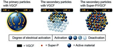
The differences in the morphologies of the active materials might result in different electrical conduction pathways along the active materials. As demonstrated in Fig. 3a, once the fiber-like conductive additive (VGCF) comes into contact with the primary particles, it builds an “expressway” for electron transfer and thus facilitates electron transfer across the particles. In contrast, considering the poor electrical conductivity of the NCM primary particles, even if VGCF forms contacts with the nano/micro hierarchical NCM particles, electron transfer would be limited only to the directly connected adjacent particles (Fig. 3b). To achieve an integrated conductive network across the entire range of primary particles within a secondary NCM particle, the nano-sized Super-P should be well dispersed and be placed between neighboring primary particles, to build a “local road” of electron transfer to facilitate electron transfer among the entire assembly of particles (as described in Fig. 3c). Such morphological features were verified by the SEM images in Fig. 1. Consequently, the use of VGCF and Super-P induces synergistic improvement of the electrical conduction of the NCM cathode.


image file: c5ra19056h-f3.tif
Fig. 3 Schematic illustration of electrical activation of the cathode active materials associated with conductive additive: (a) primary particle with VGCF, (b) secondary particle with VGCF, and (c) secondary particle with Super-P/VGCF.

The electrochemical parameters such as the CV, cycle performance, and rate capability of each cathode system were estimated. Fig. 4 shows the cyclic voltammograms of LCO, LFP, and NCM as a function of the conductive additives. As the VGCF ratio increased, the redox peak profile of LCO and LFP became more spiculate, while NCM produced the sharpest peak in the case of Super-P/VGCF which is well consistent with the electrical conductivity data for the cathodes presented in Fig. 2.19 This might be attributed to the polarization that arises from the increased electrode resistance.


image file: c5ra19056h-f4.tif
Fig. 4 Cyclic voltammograms of the unit cells with various conductive additives for (a) LCO, (b) LFP, and (c) NCM (scan rate = 0.1 mV s−1).

As shown in Fig. 5, regardless of the type of cathode material (LCO, LFP, and NCM), the cycle performance and the rate capability were in accordance with the electrical conductivity of the cathode. Cathodes with higher electrical conductivity exhibited better capacity retention during the cycle performance and rate capability tests. For the LCO and LFP cathodes, the VGCF showed the best performance, while in case of the NCM, the Super-P/VGCF combination produced the best performance as follows: (1) during the cycle performance test, Super-P = 9.6%, Super-P/VGCF = 39.3%, VGCF = 68.7% after 70 cycles for the LCO cathode, Super-P = 15.5%, Super-P/VGCF = 25.9%, VGCF = 61.4% for the LFP cathode, and Super-P = 70.9%, Super-P/VGCF = 75.9%, VGCF = 56.2% after 70 cycles for the NCM cathode. (2) During the rate capability test, Super-P = 17.7%, Super-P/VGCF = 13.7%, VGCF = 50.4% at the 35th cycle (8C) for the LCO cathode, Super-P = 0.1%, Super-P/VGCF = 72.7%, VGCF = 76.9% at the 25th cycle (3C) for the LFP cathode, and Super-P = 48.8%, Super-P/VGCF = 70.9%, VGCF = 23.5% at the 15th cycle (5C) for the NCM cathode.


image file: c5ra19056h-f5.tif
Fig. 5 Cycle performance and rate capability of the unit cells for (a and b) LCO, (c and d) LFP, and (e and f) NCM employing different types of conductive additives (Super-P, Super-P/VGCF, and VGCF).

Conclusions

The effect of the VGCF-to-Super-P ratio on the properties of various types of cathodes, including LCO, LFP, and NCM, was investigated. Regardless of the size of the active materials, the highest electrical conductivity was obtained with VCGF for the cathodes composed of primary particles (i.e., LCO and LFP), whereas the highest electrical conductivity was achieved with the Super-P/VGCF mixture for the cathodes composed of secondary particles (NCM). Well-dispersed, powdery Super-P facilitates electron transfer over constituent primary particles in the nano/micro hierarchical structures of NCM. The superior performance of the unit cells was consistent with the electrical conductivity trends for the cathodes. For all the studied cathodes, cathodes with higher electrical conductivity showed improved cycle performance and rate capability.

Acknowledgements

This work was supported by the Human Resource Training Program for Regional Innovation and Creativity through the Ministry of Education and National Research Foundation of Korea (NRF-2014H1C1A1066977) and the Commercializations Promotion Agency for R&D Outcomes (COMPA) funded by the Ministry of Science, ICT and Future Planning (MISP).

Notes and references

  1. M. Armand and J.-M. Tarascon, Nature, 2008, 451, 652–657 CrossRef CAS PubMed.
  2. M. S. Whittingham, Chem. Rev., 2004, 104, 4271–4302 CrossRef CAS PubMed.
  3. T. Ohzuku and R. J. Brodd, J. Power Sources, 2007, 174, 449–456 CrossRef CAS.
  4. C. Venkateswara Rao, A. Leela Mohana Reddy, Y. Ishikawa and P. M. Ajayan, ACS Appl. Mater. Interfaces, 2011, 3, 2966–2972 Search PubMed.
  5. T. H. Kim, J. S. Park, S. K. Chang, S. Choi, J. H. Ryu and H. K. Song, Adv. Energy Mater., 2012, 2, 860–872 CrossRef CAS.
  6. G. Liu, L. Wen and Y. Liu, J. Solid State Electrochem., 2010, 14, 2191–2202 CrossRef CAS.
  7. Y.-K. Sun, Z. Chen, H.-J. Noh, D.-J. Lee, H.-G. Jung, Y. Ren, S. Wang, C. S. Yoon, S.-T. Myung and K. Amine, Nat. Mater., 2012, 11, 942–947 CrossRef CAS PubMed.
  8. T. Ohzuku and Y. Makimura, Chem. Lett., 2001, 744–745 CrossRef CAS.
  9. C. Daniel, D. Mohanty, J. Li and D. L. Wood, Review on Electrochemical Storage Materials and Technology: AIP Conference Proceedings, 2014 Search PubMed.
  10. T. Ohzuku and Y. Makimura, Chem. Lett., 2001, 642–643 CrossRef CAS.
  11. X. Zhang, W. Jiang, A. Mauger, F. Gendron and C. Julien, J. Power Sources, 2010, 195, 1292–1301 CrossRef CAS.
  12. S. Jang, S.-H. Kang, K. Amine, Y. Bae and Y.-K. Sun, Electrochim. Acta, 2005, 50, 4168–4173 CrossRef CAS.
  13. F. Wu, M. Wang, Y. Su, S. Chen and B. Xu, J. Power Sources, 2009, 191, 628–632 CrossRef CAS.
  14. Y.-C. K. Chen-Wiegart, Z. Liu, K. T. Faber, S. A. Barnett and J. Wang, Electrochem. Commun., 2013, 28, 127–130 CrossRef CAS.
  15. B. Jin, H.-B. Gu and K.-W. Kim, J. Solid State Electrochem., 2008, 12, 105–111 CrossRef CAS.
  16. B. Jin, H.-B. Gu, W. Zhang, K.-H. Park and G. Sun, J. Solid State Electrochem., 2008, 12, 1549–1554 CrossRef CAS.
  17. R. Yuge, N. Tamura, T. Manako, K. Nakano and K. Nakahara, J. Power Sources, 2014, 266, 471–474 CrossRef CAS.
  18. G. Sun, B. Jin, G. Sun, E. Jin, H.-B. Gu and Q. Jiang, J. Appl. Electrochem., 2011, 41, 99–106 CrossRef CAS.
  19. B. Jin, E. M. Jin, K.-H. Park and H.-B. Gu, Electrochem. Commun., 2008, 10, 1537–1540 CrossRef CAS.
  20. J. Jeong, H. Lee, J. Choi, M.-H. Ryou and Y. M. Lee, Electrochim. Acta, 2015, 154, 149–156 CrossRef CAS.
  21. B. Son, M.-H. Ryou, J. Choi, T. Lee, H. K. Yu, J. H. Kim and Y. M. Lee, ACS Appl. Mater. Interfaces, 2013, 6, 526–531 Search PubMed.
  22. J. Choi, B. Son, M.-H. Ryou, S. H. Kim, J. M. Ko and Y. M. Lee, J. Electrochem. Sci. Technol., 2013, 4, 27–33 CrossRef CAS.
  23. Z.-D. Huang, B. Zhang, Y.-B. He, S.-W. Oh, Y. Yu and J.-K. Kim, J. Electrochem. Soc., 2012, 159, A2024–A2028 CrossRef CAS.
  24. Q. Lin and J. N. Harb, J. Electrochem. Soc., 2004, 151, A1115–A1119 CrossRef CAS.
  25. K. Sheem, Y. H. Lee and H. S. Lim, J. Power Sources, 2006, 158, 1425–1430 CrossRef CAS.
  26. X. Li, F. Kang and W. Shen, Electrochem. Solid-State Lett., 2006, 9, A126–A129 CrossRef CAS.
  27. V. Rao, Y. Ishikawa and P. Ajayan, ACS Appl. Mater. Interfaces, 2011, 3, 2966–2972 Search PubMed.
  28. M. Endo, Y. Kim, T. Hayashi, K. Nishimura, T. Matusita, K. Miyashita and M. Dresselhaus, Carbon, 2001, 39, 1287–1297 CrossRef CAS.
  29. M.-S. Wu, J.-T. Lee, P.-C. J. Chiang and J.-C. Lin, J. Mater. Sci., 2007, 42, 259–265 CrossRef.
  30. X. Li, F. Kang, X. Bai and W. Shen, Electrochem. Commun., 2007, 9, 663–666 CrossRef CAS.
  31. X.-M. Liu, Z. Dong Huang, S. Woon Oh, B. Zhang, P.-C. Ma, M. M. Yuen and J.-K. Kim, Compos. Sci. Technol., 2012, 72, 121–144 CrossRef CAS.
  32. S. W. Oh, S. T. Myung, S. M. Oh, K. H. Oh, K. Amine, B. Scrosati and Y. K. Sun, Adv. Mater., 2010, 22, 4842–4845 CrossRef CAS PubMed.
  33. I. H. Son, J. H. Park, S. Kwon, S. Park, M. H. Rümmeli, A. Bachmatiuk, H. J. Song, J. Ku, J. W. Choi and J.-M. Choi, Nat. Commun., 2015, 6, 1–7 Search PubMed.
  34. H.-S. Kim, M. Kong, K. Kim, I.-J. Kim and H.-B. Gu, J. Power Sources, 2007, 171, 917–921 CrossRef CAS.
  35. P. G. Bruce, B. Scrosati and J. M. Tarascon, Angew. Chem., Int. Ed., 2008, 47, 2930–2946 CrossRef CAS PubMed.

Footnote

These authors contributed equally to this work.

This journal is © The Royal Society of Chemistry 2015
Click here to see how this site uses Cookies. View our privacy policy here.