
Largely enhanced fracture toughness of an immiscible polyamide 6/acrylonitrile–butadiene–styrene blend achieved by adding chemically modified graphene oxide
Wenbin Huang,
Tingting Zhang,
Jinghui Yang*,
Nan Zhang,
Ting Huang and
Yong Wang*
Key Laboratory of Advanced Technologies of Materials (Ministry of Education), School of Materials Science and Engineering, Southwest Jiaotong Universtiy, Erhuan Road, North I, No. 111, Chengdu, Sichuan 610031, China. E-mail: yangjinghui_84@163.com; yongwang1976@163.com; Tel: +86 28 87602714 Tel: +86 28 87603042
First published on 20th November 2015
Abstract
In this work, chemically modified graphene oxide was successfully prepared by emulsion polymerization of styrene, leading to grafting polystyrene (PS) onto graphene oxide (GO). Different contents of polystyrene grafted graphene oxide (PS–GO) were incorporated into immiscible polyamide 6/acrylonitrile–butadiene–styrene (PA6/ABS) blend and it was expected that PS–GO could tune the morphology and improve mechanical property. The mechanical testing showed a great improvement on ductility of polymer blends, in which the elongation at break increased by nearly 400% and the impact strength increased by nearly 200% with only 0.5 wt% PS–GO. The underlying mechanism for toughening was carefully discussed via investigations on effects of PS–GO on morphology, chain mobility as well as interfacial interaction. The morphology changes of the blend with PS–GO show slight increase of continuity of ABS. The fracture morphologies showed that the addition of PS–GO induced enhanced interfacial adhesion, exhibiting finer fracture morphology. DMA results verified the enhanced interfacial interaction between ABS and PA6 with the addition of PS–GO. Furthermore, the results demonstrated the interface localization of PS–GO in PA6/ABS. Combined with these observations, it was suggested that the PS–GO located at interface of immiscible blends PA6/ABS and enhanced the interfacial adhesion via the dual interactions with two components, in which one was the electronic stacking interaction between grafted PS on PS–GO and ABS while the other one was the interaction between polar groups on PS–GO and PA6, finally resulting in a great improvement on ductility.
1. Introduction
Polymer blending is an effective and economical way to develop new materials with synergistic properties, and has attracted a great number of scientists and researchers.1 By varying the composition of polymers or tailoring processing methods, a variety of morphologies and its resultant properties can be achieved. However, the unfavorable enthalpy of mixing two polymers often leads to macro phase separation of polymer blends, which further results in weak interfacial adhesion with few chain entanglements. The resultant mechanical properties, especially for toughness or ductility, are deteriorated.2,3 Hence, improving the interface adhesion is important to achieve the exceptional properties via blending two polymers. The classical approach to tailor the interfacial adhesion is to incorporate copolymers which act as emulsifiers/surfactants to lower the interfacial tension, resulting in an interfacial enhancement or compatibilization of polymer blends.4,5Recently, the addition of nanofillers to an immiscible blend has become a new pathway to tailor the morphology of polymer blends and has also aroused great interests.6–8 Firstly, the selective adsorption of polymer chains on nanofillers can rebuild the thermodynamic states of polymer blends, leading to a variety of morphologies; secondly, the localization of nanofillers at interface can retard the coalescence of phase domain to further stabilize the phase structures. Besides these effects, the nanofillers impart attractive properties, such as extra-high modulus and strength, excellent conductivity, and optical and magnetic functions. Among these nanofillers, graphene and its derivatives, as new types of two-dimensional fillers, have attracted a great deal of interest. They are widely applied for the strengthening and toughening the polymer materials because of their intrinsic excellent properties9,10 and enhanced interfacial adhesion which is contributed by the large aspect ratio and wrinkles of “soft” graphene.11 For example, Rafiee et al. firstly reported considerably enhanced fracture toughness of graphene filled epoxy composites. The toughness of graphene filled epoxy showed an increase with only 0.125 wt% graphene. The toughening mechanism was ascribed to the effective crack deflections induced by enhanced specific surface areas and two-dimensional geometry of graphenes.12 Specially, graphene oxide (GO), which has been extensively investigated as promising precursors for the mass production of graphene, exhibits a unique type of building block with hydrophilic oxidative debris on the edge and hydrophobic domains on the basal plane.11,13,14 Therefore, GO exhibits amphiphilic feature, and is applied in polymer blended materials as surfactants or emulsifiers. Feng et al. firstly incorporated GO into an immiscible PA6/polyphenylene oxide (PPO) blends, and compatibilization of blends can be realized due to the electronic stacking interaction between GO sheets and PPO as well as the hydrogen bonding between oxidized groups and PA6.15 In a similar way, Feng et al. demonstrated that GO covalently functionalized with polypropylene (PP) chains was potent compatibilizers for PP/PPO blends, because the PP chains grafted on GO could strengthen the interfacial entanglement between GO and nonpolar PP.16 Finer morphologies and higher ductility of PS/polymethyl methacrylate (PMMA) was induced by the GO sheets grafted with the P(St-co-MMA) copolymer.17 With the development of chemical functionalization, the GO with high reactivity can be effectively decorated by a variety of chemical groups, and followed by reduction to obtain various chemically grafted graphene.18–20 Based on the emergency of GO decorated by various functional groups, graphene and its derivatives based polymer nanocomposites have been extensively investigated.21–23
Immiscible blends of PA6 and acrylonitrile–butadiene–styrene (ABS) are of commercial significance in industrial products. However, inherent immiscibility between ABS and PA6 limits their application in developing new materials, especially interfacial adhesion is still a weak point. As we mentioned above, graphene and its derivatives are good candidates for improving interactions between two polymers due to the “amphiphilic” effects originated from possible interaction between chemically modified graphene and polymer pairs. In this way, polystyrene (PS) grafted graphene oxide is chemically designed to strengthen interfacial adhesion of the immiscible blends PA6/ABS. It is expected that in the blend composites, PS chains on the edge is proposed to strengthen the interaction between PS–GO and ABS; and PA6 could form hydrogen bonding with oxidized groups on the PS–GO. It is demonstrated that upon only 0.5 wt% PS–GO was incorporated into PA6/ABS, the elongation at break as well as impact strength shows great improvement. The underlying toughening mechanisms are carefully discussed in a viewpoint of interfacial adhesion induced by chemically modified reduced graphene oxide.
2. Experimental
2.1 Materials
All the materials used in this study are commercially available. PA6 (TP4208) with a melt flow rate (MFR) of 35.5 g/10 min (225 °C/2.16 kg) was obtained from Zig Sheng Industrial Co., Ltd., PR China. ABS (PA757) with MFR of 1.8 g/10 min (200 °C/5 kg) was supplied by CHIMEI CORPORATION. Graphite powder with an average particle size of 10–20 μm and a purity of >95% were purchased from Qingdao Heilong Graphite Co., Ltd. Graphene oxide (GO) were prepared from natural graphite powder by oxidation with KMnO4 in concentrated H2SO4 according to modified Hummers method.24 All other chemicals were obtained as analytical grade products and used without further purification.2.2 Fabrication
![[thin space (1/6-em)]](https://www.rsc.org/images/entities/char_2009.gif) :50, and the content of PS–GO was varied from 0 to 1 wt%. The sample notation was defined as P5A5Gx, where x represented the content of PS–GO in the blend composites. For example, P5A5G0.5 represented that PS–GO content was 0.5 wt%. For comparison, the binary PA6/ABS (50/50 wt%) blend, which was named as P5A5, was also prepared through the completely same processing procedures as was done for the blend composites.
:50, and the content of PS–GO was varied from 0 to 1 wt%. The sample notation was defined as P5A5Gx, where x represented the content of PS–GO in the blend composites. For example, P5A5G0.5 represented that PS–GO content was 0.5 wt%. For comparison, the binary PA6/ABS (50/50 wt%) blend, which was named as P5A5, was also prepared through the completely same processing procedures as was done for the blend composites.2.3 Characterization
3. Results and discussion
3.1 Preparation and characterization of PS–GO
In order to evaluate the grafting efficiency, TEM was applied to observe the morphology of PS–GO. The TEM images (Fig. 1a) of the PS–GO distinctly reveal that synthesized polystyrene with a width of several couples of nanometers are attached along the edges of the stacked nanosheets with thickness of several nanometers. The similar morphology can be found with a similar ellipsoidal structure in PS grafted graphene.25 FTIR spectra analysis was performed to confirm the chemical components of the PS–GO. Fig. 1b illustrates the FTIR spectra of the rGO, and PS–GO. Both the two curves of the two samples exhibit characteristic peaks at 3500 cm−1, 1650 cm−1 and 1100 cm−1. The band at 3500 cm−1 is attributed to the presence of free or associated hydroxyl groups and the broad peak at 1100 cm−1 derives from the associated C–O stretching vibrations, both of which are from the adsorbed bound water or the unreduced hydroxyl groups on the rGO. The band located at 1650 cm−1 is assigned to the C![[double bond, length as m-dash]](https://www.rsc.org/images/entities/char_e001.gif) C stretching vibrations in carboxyl and skeleton. As for the PS–GO, the newly emerged peaks located at 1580, 1490, 1446, 750, 530 cm−1 correspond to absorptions of the benzene ring of PS segments, while the peak at 2922 cm−1 arises from the attachment of additional methylene groups. It is obviously seen from the FTIR spectra that the PS chains are attached on the rGO. It should be noted that during the preparation of PS–GO, the self-polymerized PS and residual monomer have been carefully washed and removed. Hence, all the characterization of PS–GO is for the grafted PS on rGO. The underlying mechanism for functionalization is derived from the in situ emulsion polymerization and subsequent reduction of graphene oxide. During the emulsion polymerization, the surfactant micelles were firstly adsorbed onto the edge of graphene oxide nanosheets which were full of oxygen-containing groups; styrene monomers were attached on the hydrophobic end of surfactant, and then initiator was applied to initiate the emulsion polymerization.19
C stretching vibrations in carboxyl and skeleton. As for the PS–GO, the newly emerged peaks located at 1580, 1490, 1446, 750, 530 cm−1 correspond to absorptions of the benzene ring of PS segments, while the peak at 2922 cm−1 arises from the attachment of additional methylene groups. It is obviously seen from the FTIR spectra that the PS chains are attached on the rGO. It should be noted that during the preparation of PS–GO, the self-polymerized PS and residual monomer have been carefully washed and removed. Hence, all the characterization of PS–GO is for the grafted PS on rGO. The underlying mechanism for functionalization is derived from the in situ emulsion polymerization and subsequent reduction of graphene oxide. During the emulsion polymerization, the surfactant micelles were firstly adsorbed onto the edge of graphene oxide nanosheets which were full of oxygen-containing groups; styrene monomers were attached on the hydrophobic end of surfactant, and then initiator was applied to initiate the emulsion polymerization.19
 | ||
| Fig. 1 (a) TEM photo of PS–GO; (b) FTIR spectra of rGO and PS–GO. | ||
Fig. 2 shows thermogravimetric curves from the rGO, polystyrene and PS–GO. As for polystyrene, the decomposition starts at 350 °C. The mass loss of rGO starts at 200 °C, which is attributed to the pyrolysis of oxygen-containing groups such as hydroxyl, carboxyl etc. The PS–GO exhibits two characteristic mass losses, one appears at 200 °C and the other one starts at 350 °C, corresponding to the pyrolysis of oxygen-containing groups and decomposition of PS, respectively. Combining with FTIR, TGA and TEM results, it is obviously found that PS is successfully grafted onto the surface of graphene sheets; although a small amount of oxygen containing groups are still attached on the graphene surface. It should be noted that reduction could not completely remove the polar groups, hence a small amount of oxygen containing groups are still unremoved.
 | ||
| Fig. 2 TGA curves of the rGO, PS and PS–GO. | ||
Raman spectroscopy is a powerful tool for describing the carbonaceous materials with chemical functionalization or physical wrapping via distinguishing ordered and disordered crystal structures of carbon. Fig. 3 shows the Raman spectra of rGO and PS–GO to evaluate the structures of rGO before and after functionalization. The main features of graphene in the Raman spectra are G peak at 1591 cm−1 and D peak at 1336 cm−1. The G peak originates from the in-plane vibration of sp2 carbon atoms while the D peak is assigned to the some structure defects such as localized sp3 carbon atoms from oxygen containing functional groups, vacancies and topological defects, which may benefit the chemical grafting of polymers to graphene nanosheets. It can be observed that the two curves for rGO and PS–GO are similar in terms of the shapes and positions of G and D peaks. It is necessary to note that the peak intensity ratios I(D)/I(G) of rGO and PS–GO are 1.25 and 1.18, respectively. This result can also be explained if new graphitic domains are created that are higher in number after grafting for PS–GO.26 Such disorders and defects are also reflected in the red-shifted D peak (such as from 1336 cm−1 to 1333 cm−1 in PS–GO) and the red-shifted (such as from 1591 cm−1 to 1584 cm−1 in PS–GO) of PS–GO compared with rGO. According to Rao,27 the G band position varies from sample to sample because of the difference in the number of layers, so the red-shifted G peak may be attributed to that the G-band position decreases with an increasing number of layers in their solid states.28 The red-shifted D peak may be associated with PS chains chemically bonding to rGO. On the other hand, the substantial structure of the carbon network in rGO and PS–GO has been maintained after PS grafting onto the edge of graphene nanosheets.
 | ||
| Fig. 3 Raman spectra of rGO and PS–GO. | ||
For a further confirmation, the XRD patterns of rGO and PS–GO were recorded in Fig. 4. The (002) diffraction peak of rGO is assigned at about 24°, and the interlayer spacing is about 0.37 nm. Concerning about the PS–GO, the (002) diffraction peak is moved forward to 21.4° with corresponding spacing of 0.41 nm. The XRD results illustrate that attachment of PS onto the edge of PS–GO nanosheets can disturb the van der Waals interaction of stacked PS–GO layers, exfoliate the PS–GO layers and furthermore enlarge the spacing of the nanosheets. Combined with the results shown above, it should be mentioned that some oxygen-containing groups for PS–GO are still unremoved as shown above. Hence, the GO sheets were partially reduced in order that the amounts of oxygen containing groups were lowered and the strong polarity of GO was avoided. In this case, the PS–GO show “amphiphilic” characteristic features, which means unremoved oxygen containing groups exhibit the possibility to interact with polar polymers or polymers containing some functional groups29 while the grafted PS would like to entangle with polymers containing benzene rings or carbon structures via intermolecular interaction, which could be an important driving force to tailor the morphology of immiscible blends, especially for the compatibilization of immiscible blends. Based on these predictions, polymer blend comprised of polar polymer PA6 and ABS containing PS segments was chosen as our research target. Importantly, PA6/ABS is of great potential in industrial and commercial fields, therefore, investigations on the effects of PS–GO on PA6/ABS is of great significance.
 | ||
| Fig. 4 XRD spectra of rGO and PS–GO. | ||
3.2 Mechanical property of ternary composites
The elongation at break is an important factor to directly judge toughness of polymer blends. The strain–stress curves sheds light on the load vs. deformation features of the blend composites. Fig. 5a displays the representative strain–stress behaviors of the various blended composites. It can be found that PA6/ABS with and without PS–GO exhibit similar deformation behavior containing elastic deformation, yielding and fracture. Elongation at break of the blend without PS–GO is only 11%; while it is evident from Fig. 5a that addition of PS–GO has increased the ductility. When 0.3 and 0.5 wt% PS–GO were incorporated into blends, the elongation at break increased to 25% and 42% respectively indicating that these blends have a greatly improved ductility. However, a decrease of elongation at break can be found possibly due to the aggregation of 1 wt% PS–GO. For a clear illustration, the tensile strength, modulus and elongation at break of samples with PS–GO are respectively shown in Fig. 5b. As for blend composites with PS–GO, great improvement on elongation at break can be achieved without any loss of tensile strength and modulus. Even the tensile strength and modulus exhibit slight increase which should be attributed to the reinforcing effect of PS–GO. On the other hand, seen from Fig. 5c, it is found that with increasing the concentration of PS–GO, the impact strength increases from 9.0 kJ m−2 to 21 kJ m−2 when 0.5 wt% PS–GO are incorporated into polymer blends. Similar to the elongation at break, when 1 wt% PS–GO are incorporated into polymer blends, aggregates of PS–GO cause the decrease of impact strength. The increase on impact strength reveals the presence of PS–GO in immiscible blend PA6/ABS is also benefit for the energy adsorption during impact strength, and a further study concerning about effects of PS–GO on the crack growth during the impact testing are needed in a future work. | ||
| Fig. 5 (a) Typical strain–stress curves of samples and (b) the corresponding tensile properties; (c) variation of impact strength of PA6/ABS/PS–GO blend composites versus PS–GO content. | ||
As described above, the common toughening methods for the immiscible blend PA6/ABS reported in the literatures are mainly related to the addition of copolymer of other component, such as carbon nanotubes (CNTs). To better understand the toughening effect of PS–GO in the immiscible PA6/ABS blend, a comparison between our results and other results reported in the literatures are carried out as shown in Fig. 6, in which CNT, EMA–GMA (ethylene methyl acrylate–glycidyl methacrylate), and EnBACO–MAH (ethylene–n-butyl acrylate–carbon monoxide–maleic anhydride) were utilized to modify PA6/ABS blends to improve the interfacial adhesion and achieve the desired improvement on mechanical properties.30,31 Among all these fillers or components, it is clearly seen that our PS–GO exhibits the most effective toughening on PA6/ABS blends; in contrast, CNTs, EMA–GMA and EnBACO–MAH did not show any positive role on the improvement of toughness. It is clear that great improvement on fracture toughness and ductility is obtained by PS–GO, the underlying mechanism needs to be clarified.
 | ||
| Fig. 6 Elongation at break of PA6/ABS with the addition of different fillers for comparison. | ||
3.3 Toughening mechanism
Morphology of polymer blends is one of the decisive factors that influence the final properties. Fig. 7 shows the morphologies of PA6/ABS blends with different contents of PS–GO. For a clear observation, the ABS component was removed using chemically etching of THF; therefore, the dark domain corresponds to the removed ABS and the gray domain is the PA6. All the samples indicate that ABS phase disperse in the PA6 matrix. It should be noted that the weight ratio of PA6 and ABS is 50:50, and the morphology of PA6/ABS is in the intermediate state between sea–island and co-continuous structure. Seen from Fig. 7, more elongated or connected ABS domain could be differentiated in polymer blend composites with increasing the content of PS–GO, although no significant change on phase morphology can be observed. The continuity of PA6 domain, calculated by Image J1.47n software,32 which was used to transform the SEM images with the same magnification into numerical values, exhibits a gradual increase with increasing the content of PS–GO as show in Fig. 8. As for the PA6/ABS blends, the gray domain with the continuity of 69% can be found. The continuity of PA6 is gradually increased to 76.2%, 75.0% and 86.7% when 0.3, 0.5, 1.0 wt% PS–GO are present in the blend composites, respectively. The increasing trend for the continuity of PA6 could be observed with increasing the content of PS–GO. The increased continuity exhibits morphology coarsening and indicates the decreased interfacial areas which enables elongated phase to share more in the load bearing capability, suggesting that increased continuity is more effective for lowering interfacial tension.33,34 Based on these observations and analysis, the continuity induced by PS–GO plays a positive role on the improvement of toughness. However, when 0.5 wt% PS–GO were incorporated into polymer blends, the toughness including both elongation at break and compact strength exhibit greatest increase while the continuity shows only slight increase. It is clear the phase morphology is not the key to the improvement of toughness.
 | ||
| Fig. 7 SEM photos of PA6/ABS/PS–GO blend composites with different contents. (a) 0 wt%; (b) 0.3 wt%; (c) 0.5 wt%; (d) 1 wt%. | ||
 | ||
| Fig. 8 Continuity of PA6 in PA6/ABS blends with different contents of PS–GO. | ||
In order to further explore the toughness mechanism of PS–GO in PA6/ABS, the tensile-fractured surfaces along the tensile direction were observed by SEM and the results are shown in Fig. 9. As shown in Fig. 9a, the blank PA6/ABS blend exhibits the typical layered fibrillation structure due to the severe plastic deformation of matrix during the tensile test. It can be observed that some dispersed ABS particles have been pulled out from the matrix, as shown in inset of Fig. 9a, indicating the weak interfacial adhesion between PA6 and ABS. As for the blend with PS–GO, the similar morphology with fibrillation structure could be observed. However, the ABS particles disappeared and only the deformed fibrils of ABS and PA6 could be found, finer morphology without severe detaching is observed in PA6/ABS blend with PS–GO. These observations indicate the interfacial adhesion between PA6 and ABS is identified by PS–GO.
 | ||
| Fig. 9 SEM images showing the tensile-fractured surface morphologies of (a) PA6/ABS blend and (b) PA6/ABS/PS–GO blend composites with 0.5 wt% PS–GO. | ||
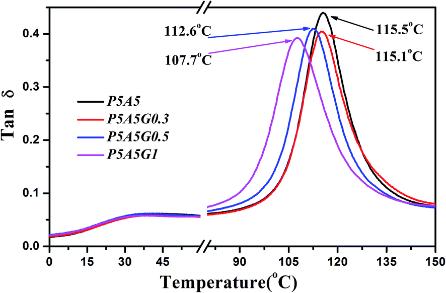
To clarify this observation, the relaxation behaviors of all samples were investigated by DMA to evaluate the chain mobility of PA6 and ABS with incorporation of PS–GO. Fig. 10 shows the loss factor (tanδ) for PA6/ABS blend and their blend composites with PS–GO. The loss factor peak at temperature of 30 °C is assigned to the glass transition of PA6 chain segments; the loss factor peak at higher temperature of 116.5 °C is for the glass transition of PS chain segments of ABS. It should be found that Tg of ABS shifts to lower temperature gradually with increasing the contents of PS–GO, which indicates that the glass transition behaviors of ABS component are influenced by PS–GO. This confirms that the ABS chains diffuse or dissolve in nylon 6 domain when PS–GO is incorporated in immiscible blends, as demonstrated in polyvinylidene fluoride (PVDF)/PA6/GO ternary composites.35 On the other hand, the Tg of PA6 exhibits little change with incorporation of PS–GO. The different Tg variation trend of PA6 and ABS illustrates the possibility of PS–GO locating at interface of PA6 and ABS, furthermore promoting the interfacial adhesion.
 | ||
| Fig. 10 Loss factor of the PA6/ABS blend and the PA6/ABS/PS–GO blend composites obtained through DMA measurements. | ||
In order to verify the localization of PS–GO at interface, the interfaces of the immiscible PA6/ABS blends with and without PS–GO have been carefully observed as shown in Fig. 11, the interfaces for the blends with PS–GO (Fig. 11b) are coarser compared with that of the blank PA6/ABS blend (Fig. 11a) and some folds of sheets-like structure can be found as shown by arrows. On the other hand, it should be noted that the PS–GO with two dimensional planes exhibits high interfacial stability, allowing it to more readily cover the interface.36 Therefore it is reasonably proposed that PS–GO is located at interface, leading to the polymer chain diffusion crossing the interface and variation of Tg of ABS.
 | ||
| Fig. 11 Interface of (a) PA6/ABS blend and (b) PA6/ABS/PS–GO blend composite with 0.5 wt% PS–GO. | ||
According to the previous observation, the toughening mechanism of PS–GO in the immiscible PA6/ABS blend can be further understood as shown in the schematic picture in Fig. 12. Phase separation with clear interface can be found in neat PA6/ABS blend due to the unfavorable interaction between PA6 and ABS. With the introduction of PS–GO, these nanosheets functionalized PS chains can adsorb some PS section of ABS on their basal planes due to the π–π interaction between PS section in ABS and PS chains grafted on GO.37 On the other hand, the unremoved groups containing oxygen on GO basal planes have strong interaction with PA6 which is originated from the hydrogen bonding between amide group of PA6 and the hydroxyl on rGO.38 On the other hand, as we know, the fillers in immiscible blends would like to migrate to component with lower viscosity or better interaction with filler. In this case, PS–GO are inclined to migrate from ABS/PS–GO masterbatch to the PA6 due to the lower viscosity of PA6 and the hydrogen bonding between PS–GO and PA6. As we know, due to the π–π interaction between PS section in ABS and PS chains grafted on GO, partial ABS are adsorbed on PS–GO in ABS/PS–GO masterbatch. When ABS/PS–GO blended with PA6, PS–GO would like to migrate from ABS to PA6 with lower viscosity. In this case, partial ABS adsorbed on PS–GO could solve or diffuse into PA6 domain as accompanied with the migration of PS–GO from ABS to PA6; and the phase coarsening may be allowed. It is worthy to be noted that partial PS–GO may migrate to the interface and weave across the interface, realizing the formation of entanglements and reducing unfavorable contacts between PA6 and ABS as shown in Fig. 12. In this case, the interfacial adhesion was intensified, leading to the great improvement of ductility. On the other hand, in a viewpoint of intrinsic structure of graphene, the wrinkles on PS–GO can enhance the interfacial adhesion between polymer and PS–GO; and the deflection of crack induced by graphene may also play a positive role on toughening which needs a further discussion in future needs work.9–11
 | ||
| Fig. 12 Schematic showing of dual effects of PS–GO with PA6 and ABS components. | ||
4. Conclusion
In summary, we chemically tailored the structure of rGO via grafting PS chains onto the rGO. With the incorporation of PS–GO into the immiscible PA6/ABS blend, both the tensile ductility and impact strength of the blend composites are greatly enhanced, indicating the toughening effect of PS–GO. Further studies on the morphology demonstrated that the addition of PS–GO slightly increase the continuity of ABS phase, obviously it is not the key to the great improvement on ductility. DMA, SEM observation results reveal the underlying mechanism for the toughening, which is believed to be the enhanced interfacial adhesion between ABS and PA6 with the presence of PS–GO locating at interface. Furthermore, the intensified interfacial adhesion could be attributed to the dual effects of PS–GO with two components, in which one is the π–π interaction between PS section in ABS and PS chains grafted on PS–GO, and the other is the hydrogen bonding between PS–GO and PA6.Acknowledgements
Authors express their sincere thanks to the National Natural Science Foundation of China (51473137, 51203129 and 50973090) for supporting this work.References
- L. A. Utracki, Polymer Alloys and Blends, Hanser Publishers, New York, 1990 Search PubMed.
- K. Joseph, S. Varghese, G. Kalaprasad, S. Thomas, L. Prasannakumari, P. Koshy and C. Pavithran, Eur. Polym. J., 1996, 32, 1243 CrossRef CAS.
- S. Y. Fu, X. Q. Feng, B. Lauke and Y. W. Mai, Composites, Part B, 2008, 39, 933 CrossRef.
- D. R. Paul and C. B. Bucknall, Polymer Blends: Formulation and Performance, John Wiley & Sons, New York, 2000 Search PubMed.
- S. C. Tjong and T. C. Ke, Eur. Polym. J., 1998, 34, 1565 CrossRef CAS.
- H. Tanaka, A. J. Lovinger and D. D. Davis, Phys. Rev. Lett., 1994, 72, 2581 CrossRef CAS PubMed.
- J. S. Hong, H. Namkung, K. H. Ahn, S. J. Lee and C. Kim, Polymer, 2006, 47, 3967 CrossRef CAS.
- L. Elias, F. Fenouillot, J. C. Majeste and P. Cassagnau, Polymer, 2008, 49, 4378 CrossRef CAS.
- A. K. Geim and K. S. Novoselov, Nat. Mater., 2007, 6, 183 CrossRef CAS PubMed.
- H. Kim, A. A. Abdala and C. W. Macosko, Macromolecules, 2010, 43, 6515 CrossRef CAS.
- S. Stankovich, D. A. Dikin, G. H. B. Dommett, K. M. Kohlhaas, E. J. Zimney, E. A. Stach, R. D. Piner, S. T. Nguyen and R. S. Ruoff, Nature, 2006, 442, 282 CrossRef CAS PubMed.
- M. A. Rafiee, J. Rafiee, I. Srivastava, Z. Wang, H. Song, Z. Z. Yu and N. Koratkar, Small, 2010, 6, 179 CrossRef CAS PubMed.
- H. He, J. Klinowski and M. Forster, Chem. Phys. Lett., 1998, 287, 53 CrossRef CAS.
- S. Stankovich, R. Piner, X. Chen, N. Wu, S. Nguyen and R. Ruoff, J. Mater. Chem., 2006, 16, 155 RSC.
- Y. W. Cao, J. Zhang, J. C. Feng and P. Y. Wu, ACS Nano, 2011, 5, 5920 CrossRef CAS PubMed.
- Y. Cao, J. Feng and P. Wu, J. Mater. Chem., 2012, 22, 14997 RSC.
- Y. Tan, L. Fang, J. Xiao, Y. Song and Q. Zheng, Polym. Chem., 2013, 4, 2939 RSC.
- W. H. Liao, S. Y. Yang, J. Y. Wang, H. W. Tien, S. T. Hsiao, Y. S. Wang and Y. F. Wu, ACS Appl. Mater. Interfaces, 2013, 5, 869 CAS.
- H. Hu, X. Wang, J. Wang, L. Wan, F. Liu, H. Zheng and C. Xu, Chem. Phys. Lett., 2010, 484, 247 CrossRef CAS.
- S. Sun, Y. Cao, J. Feng and P. Wu, J. Mater. Chem., 2010, 20, 5605 RSC.
- M. Fang, K. Wang, H. Lu, Y. Yang and S. Nutt, J. Mater. Chem., 2010, 20, 1982 RSC.
- E. Tkalya, M. Ghislandi, A. Alekseev, C. Koning and J. Loos, J. Mater. Chem., 2010, 20, 3035 RSC.
- C. Tang, G. Long, X. Hu, K. Wong, W. Lau, M. Fan, J. Mei, T. Xu, B. Wang and D. Hui, Nanoscale, 2014, 6, 7877 RSC.
- W. S. Hummers and R. E. Offeman, J. Am. Chem. Soc., 1958, 80, 1339 CrossRef CAS.
- Y. T. Liu, J. M. Yang, X. M. Xie and X. Y. Ye, Mater. Chem. Phys., 2011, 130, 794 CrossRef CAS.
- S. Stankovich, D. A. Dikin, R. D. Piner, K. A. Kohlhaas, A. Kleinhammes, Y. Jia and R. S. Ruoff, Carbon, 2007, 45, 1558 CrossRef CAS.
- C. Rao, K. Biswas, K. Subrahmanyam and A. Govindaraj, J. Mater. Chem., 2009, 19, 2457 RSC.
- J. Shen, Y. Hu, M. Shi, X. Lu, C. Qin, C. Li and M. Ye, Chem. Mater., 2009, 21, 3514 CrossRef CAS.
- R. Rafiq, D. Cai, J. Jin and M. Song, Carbon, 2010, 48, 4309 CrossRef CAS.
- X. Q. Liu, W. Yang, B. H. Xie and M. B. Yang, Mater. Des., 2012, 34, 355 CrossRef CAS.
- G. Ozkoc, G. Bayram and E. Bayramli, J. Appl. Polym. Sci., 2007, 104, 926 CrossRef CAS.
- M. Liebscher, M. O. Blais, P. Pötschke and G. Heinrich, Polymer, 2013, 54, 5875 CrossRef CAS.
- R. C. Willemse, A. P. de Boer, J. van Dam and A. D. Gotsis, Polymer, 1998, 39, 5879 CrossRef CAS.
- J. Li, P. L. Ma and B. D. Favis, Macromolecules, 2002, 35, 2005 CrossRef CAS.
- J. Yang, C. Feng, J. Dai, N. Zhang, T. Huang and Y. Wang, Polym. Int., 2013, 62, 1085 CAS.
- A. Göldel, A. Marmur, G. R. Kasaliwal, P. Pötschke and G. Heinrich, Macromolecules, 2011, 44, 6094 CrossRef.
- M. Yang, V. Koutsos and M. Zaiser, J. Phys. Chem. B, 2005, 109, 10009 CrossRef CAS PubMed.
- X. Zhang, X. Fan, H. Li and C. Yan, J. Mater. Chem., 2012, 22, 24081 RSC.
| This journal is © The Royal Society of Chemistry 2015 |