DOI:
10.1039/C5RA18552A
(Paper)
RSC Adv., 2015,
5, 104095-104100
A new microporous layer material to improve the performance and durability of polymer electrolyte membrane fuel cells
Received
10th September 2015
, Accepted 4th November 2015
First published on 6th November 2015
Abstract
Antimony doped tin oxide (ATO), a kind of semiconducting nanocrystalline material, has excellent electrochemical stability but poor electrical conductivity. Herein, ATO nanocomposites with carbon coatings are prepared by immersing ATO nano-material into dopamine solution, and then thermal treatment to improve the electrical conductivity of the ATO material. The morphology and microstructure of ATO@C/N nanocomposites are characterized using a scanning electron microscope and transmission electron microscopy. The GDLs with the MPL prepared from ATO@C/N nanocomposites are characterized by through-plane resistance testing, mercury intrusion porosimetry and surface contact angle measurement. The results of the above show that ATO@C/N nanocomposites with a 2.16 nm thick carbon coating enhance the electrical conductivity of ATO nanocrystals and exhibit higher electrochemical stability. Further, the performance of MEA fabricated with ATO@C/N as the cathode MPL is evaluated. The maximum power density approaches 1000 mW cm−2, and a slight difference in cell performance is observed compared to XC-72.
Introduction
Durability is an increasingly important issue in proton exchange membrane fuel cells (PEMFCs).1 In terms of the gas diffusion layer (GDL), one of the major challenges derives from the corrosion of the carbon material.2–4 In general, the GDL consists of a carbon paper or carbon cloth substrate and a microporous layer (MPL) composed of a mixture of carbon powder and polytetrafluoroethylene (PTFE). Its basic functions are the effective diffusion of reactant gas from flow channels to the catalyst layer, draining out liquid water from the catalyst layer to the flow channels, and conducting electrons with low resistance.5
As a crucial part of the GDL, the MPL plays an important role in the improvement of water management, thereby enhancing PEMFC performance and durability.6 Carbon powder, for example Vulcan XC-72, is commonly used as a commercial MPL material. However, the greatest problem with carbon is that it is hard to maintain its electrochemical stability under highly oxidizing, acidic conditions, although this can ensure good fuel cell performance. There have been a few studies on GDLs, such as on the effects of treatment with different amounts of PTFE,7–9 the degradation mechanism of carbon,10–12 and hydrophilic and hydrophobic treatment of MPLs.6,13 However, few involve the alternative of carbon powder or pay attention to new MPL materials. Therefore, it is meaningful to introduce other new kinds of material to replace the carbon powder. Antimony doped tin oxide (ATO) is a good alternative for the MPL material because of its physical and chemical properties: it is a typical n-type semiconducting material with excellent stability and its electrical conductivity is affected by the molar content of antimony.14,15 ATO is stable in acidic media and has a much higher corrosion resistance compared with the carbon material,16 which has led to its widespread use in electrically conducting coatings, gas sensors and solar cell transparent electrodes.17 However, its lower conductivity is a major problem compared with Vulcan XC-72.
Applying a conductive carbon coating onto the surface of ATO is an effective approach for the improvement of electrical conductivity. It has been noted that a carbon coating can enhance the electrochemical performance of nanocomposites.18–20 However, one key issue must be considered: the carbon coating should be uniform and continuous to provide rapid and continuous electron transport.18 To fully implement this approach, dopamine, a biomolecule with a strong and versatile adhesion capability, is commonly used as a coating agent and carbon precursor. This function of dopamine derives from its chemical structure that incorporates many functional groups, such as catechol and amine. It can easily self-polymerize to form a polydopamine coating on various types of substrate, including inorganic and organic surfaces, at alkaline pH values and under an oxygen atmosphere.21,22 One valuable feature of polydopamine is that the thickness of the coating layer can be controlled by varying the initial concentration of dopamine or the polymerization time.23,24 Therefore, using dopamine as a coating agent and carbon precursor provides a significant advantage in tuning the composition and properties of the coating layer, which is important for material design and optimization.
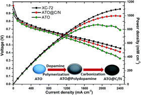
In this work, ATO is converted into ATO@C/N nanocomposites after immersing into dopamine solution and thermal treatment. The new cathode MPL prepared with ATO@C/N nanocomposites has better electrochemical stability but lower electrical conductivity and slightly poorer cell performance compared with XC-72 MPL. Nevertheless, its maximum power density approaches 1000 mW cm−2 at 2300 mA cm−2.
Experimental
Materials
Dopamine hydrochloride with MW 189.64 and purity 98% was obtained from Aladdin. ATO nanoparticles (purity > 99.97%, Sb2O5
:
SnO2 10
:
90 wt%, particle size 7–15 nm, BET surface area 65–80 m2 g−1, specific volume resistance < 10 Ω cm) were purchased from NERCN Co., China.
Preparation of ATO@C/N particles
Typically, 600 mg ATO was dispersed in 50 mL Tris-buffer (pH 8.5) to form a suspension under magnetic stirring for 30 min. Then, 100 mg dopamine was added to the above mixture under moderate stirring for 24 h. After that, the sample was centrifuged 4 times at a rotational speed of 8000 rpm, for 5 minutes each time. Subsequently, the above sample was dried under vacuum at 60 °C for 24 hours. Then, the powder was ground to obtain ATO particles with a polydopamine coating of defined thickness. Finally, the powder was heated in a quartz tube under an Ar atmosphere at a heating-up speed of 5 °C min−1, at 160 °C for 1 h and then 500 °C for 4 h, based on the procedure presented in ref. 18. After natural cooling, ATO powder with an N-doped carbon coating was obtained, which was denoted as ATO@C/N.
Preparation of the cathode GDL
GDL (Sunrise Power Co., Ltd., China) consists of a substrate and an MPL, and the substrate commonly uses commercial carbon paper (Toray) treated with PTFE to provide hydrophobic properties. The MPL slurry was prepared by mixing 64 mg Vulcan XC-72 (Cabot China Ltd.) into 640 mg 5 wt% PTFE. To prepare the cathode GDL, the MPL slurry was coated onto one side of the as-treated carbon paper by rolling with a glass rod. The coated paper was taken into an oven at 80 °C and sintered at 240 °C for 30 min, then at 350 °C for 90 min under a nitrogen atmosphere. For the new cathode GDL, 320 mg ATO@C/N nanocomposites or ATO particles were taken into 640 mg 5 wt% PTFE and sintered under the same conditions. The pressed disc method was adopted to keep the same volume fraction of XC-72 and ATO in the GDL material during the preparation process.
Material characterization
The morphology and microstructure of ATO@C/N nanocomposites were characterized using a scanning electron microscope (SEM, JSM 6360-LV) and transmission electron microscope (TEM, JEOL JEM-2000EX) operating at 120 kV. The element content and distribution in the nanocomposites were characterized by energy dispersive X-ray spectroscopy (EDS) along with SEM. To compare the pore size distribution and porosity for different GDLs, mercury intrusion porosimetry (PoreMasterGT 60) was used. The pore size distribution curve was determined according to the volume of mercury penetrating the pores versus the applied pressure. Surface contact angles of the GDLs were also measured using a Drop Shape Analyzer (DSA 100).
The through-plane resistance of the cathode GDL was measured using a mechanical device under compression. The untested sample (1 × 2 cm2) was placed between two coated gold bullions connected to a 5 A electrical current. The test pressure was applied from 1 to 10 kg cm−2 with 1 kg increments at a rate of 0.1 mm min−1. Once the test pressure reached the set value, the relevant voltage value was recorded. The through-plane resistance was calculated using eqn (1):25
where
R is the through-plane resistance,
U is the voltage,
S is the area of the tested sample and
I is the current.
Electrochemical characterization
Electrochemical measurements of the ATO@C/N sample were performed using a CHI730 electrochemical station by the conventional three-electrode method, which consisted of the as-prepared sample (working electrode), saturated calomel electrode (SCE, reference electrode) and Pt foil (counter electrode). These tests were conducted in 0.5 M H2SO4 solution saturated with high purity N2 and all the potentials are given versus the normal hydrogen electrode (NHE). Chronoamperometric testing was carried out for 2 hours to oxidize MPL materials at a constant potential of 1.2 V. Moreover, cyclic voltammetry (CV) measurements were carried out before and after oxidization with a scan rate of 50 mV s−1 and a cycling potential from −0.241 to 0.959 V.10 Carbon powder (XC-72) was also prepared as a working electrode and tested in the same way to ascertain the anti-corrosion properties of different MPL materials.
Furthermore, the electrochemical stability of cathode GDL materials was tested via the three-electrode method using a homemade setup with a BiStat potentiostat. The as-prepared GDL (1 × 2 cm2) was used as the working electrode. A graphite plate and saturated calomel electrode were employed as the counter electrode and reference electrode, respectively. To simulate the operating conditions of a fuel cell, the tests were performed for 24 h in 0.5 M H2SO4 solution saturated with high purity N2 at 70 °C.
Single-cell assembly and performance tests
The new cathode GDL prepared with ATO@C/N nanocomposites was assembled for a single fuel cell. Catalyst-coated membrane (CCM), consisting of a Nafion 212 membrane and Pt/C catalyst with a Pt loading of 0.2 and 0.4 mg cm−2 at the anode and cathode, respectively, was sandwiched between the new cathode GDL and the normal anode GDL using a hot-pressing method at 140 °C for 2 min. The utilizable area of the fuel cell was 5.0 cm2. The fuel cell performance was measured with a fuel cell impedance meter (KFM2030, Kikusui). During the test, the cell temperature was 65 °C and the humidification temperature was 65 °C for H2/O2. The flow rate of H2/O2 was 50/100 mL min−1 at 0.05 MPa. For comparison, other fuel cells were prepared with commercial GDL and the same CCM and tested under the same conditions.
Results and discussion
Preparation of samples
Scheme 1 illustrates the fabrication process of the ATO@C/N nanoparticles. Initially, ATO nanoparticles were coated with polydopamine by immersing ATO in a dopamine buffer solution (pH = 8.5). During the immersion, the polymerization of dopamine monomers occurred via a pH-induced oxidation, coupled with a color change from light blue to dark brown after 24 h. Afterwards, the ATO@polydopamine composites were annealed at 500 °C for 4 h to produce ATO@C/N.
 |
| Scheme 1 Schematic illustration of the fabrication of ATO@C/N nanocomposites. | |
Physical characterization
The energy-dispersive X-ray spectroscopy (EDS) elemental mapping of the ATO@C/N nanocomposites (Fig. 1a) shows the presence of nitrogen, demonstrating that polydopamine was transformed into an N-doped carbon coating on the ATO surface after pyrolysis. In addition, the signals of C, N and Sn on the EDS maps confirm the uniform and continuous distribution of the above elements throughout the nanocomposites, providing rapid and continuous electron transport and contributing to the increased electrical conductivity of the ATO material. Fig. 1b shows the element content of the ATO@C/N nanocomposites. The nitrogen content on the surface of ATO@C/N was calculated to be 5.94 wt% from the EDS, slightly lower than the carbon content (8.85 wt%), which fitted with the molecular structure of dopamine.
 |
| Fig. 1 (a) SEM image of ATO@C/N; EDS element maps of (b) C, (c) N and (d) Sn; and (e) element content distribution chart for ATO@C/N nanocomposites. | |
The morphology of the as-prepared ATO@C/N was examined by scanning electron microscopy (SEM) and transmission electron microscopy (TEM). Fig. 2b and c show the SEM images of ATO@C/N, which present the satiety after the ATO particles were coated with carbon and nitrogen compared with pure ATO (Fig. 2a). In addition, Fig. 2d shows the TEM image of ATO@C/N. The thickness of the C/N coating was approximately 2 nm.
 |
| Fig. 2 (a) SEM image of ATO; (b) and (c) SEM and (d) TEM images of ATO@C/N. | |
Through-plane resistance
The through-plane resistance of GDL materials has a significant effect on the contact resistance of the catalyst layer and affects the output performance of the final fuel cell.26 Fig. 3 compares the through-plane resistance of different GDL materials. The GDL prepared from XC-72 has the least through-plane resistance, while ATO materials have the highest values. The ATO@C/N shows a lower through-plane resistance than pristine ATO, but higher than XC-72 powder, particularly under higher pressure. Consequently, ATO particles with coating treatment indeed have improved electrical conductivity.
 |
| Fig. 3 Through-plane resistance of different GDL materials. | |
Electrochemical studies
To evaluate the electrochemical stability of XC-72, ATO and ATO@C/N samples, the potential value of potentiostatic oxidation was set to 1.2 V (vs. NHE). Because the hydrolysis reaction of water does not happen at this potential value, the main reaction occurring is the corrosion of carbon material,2,12 and the corrosion current increases with the intensification of the corrosion reaction. Fig. 4 shows the chronoamperometric curves of XC-72, ATO and ATO@C/N samples at constant potential (1.2 V vs. NHE) for 2 h. As can be seen, the corrosion current of ATO@C/N was approximately 0.084 μA, which was 16.8% less than that of XC-72 (0.101 μA) and 36.8% more than that of ATO (0.052 μA). The results indicated that ATO@C/N nanoparticles after coating treatment still had a higher electrochemical stability than XC-72, although it was lower compared with pristine ATO.
 |
| Fig. 4 Chronoamperometric curves for XC-72, ATO and ATO@C/N samples measured at 1.2 V vs. NHE in nitrogen-purged 0.5 M H2SO4. | |
The durability of the above materials was also evaluated by CV measurements before and after oxidation treatment with a cycling potential from −0.24 to 0.96 V (vs. NHE). In Fig. 5, a significant difference can be observed between the XC-72 CV curves and the ATO and ATO@C/N curves. It should be noted that the CV curve of ATO@C/N showed the least change, which indicated that the ATO@C/N nanocomposite had more stability. That is to say, the ATO@C/N nanocomposites performed better than XC-72 in terms of anti-corrosion ability.
 |
| Fig. 5 CV curves of XC-72, ATO and ATO@C/N samples under oxidation with potential cycling between −0.241 and 0.959 V in 0.5 M H2SO4 electrolyte, with a scan rate of 50 mV s−1. | |
To further evaluate the anti-corrosion stability of MPL materials, GDLs were tested using a potentiostat in a simulated fuel cell environment. Fig. 6 shows the CV curves of different GDLs at 70 °C. Comparing the CV diagrams before and after oxidation, it could be seen that the GDL with ATO@C/N not only had a higher ability than XC-72 GDL to resist corrosion under highly-oxidizing, acidic circumstances, but performed better than ATO GDL. Other researchers10 have illustrated that the stability decrease of GDLs prepared from XC-72 is derived from the oxidization of the carbon surface, which could be confirmed by the peak current on the CV curves. The peak current of 0.4 V (vs. SCE) corresponds with the quinone–hydroquinone redox couple, which are both oxygen-containing substances produced from the oxidation process of carbon. Based on the above electrochemical tests, the conclusion can be drawn that ATO@C/N nanocomposites with a thinner carbon coating retain the stability of the ATO material well, and reduce the corrosion of GDLs under acidic circumstances.
 |
| Fig. 6 CV curves of GDLs prepared using XC-72, ATO and ATO@C/N samples at 70 °C under oxidation with potential cycling between −0.241 and 0.959 V in 0.5 M H2SO4 electrolyte, with a scan rate of 50 mV s−1. | |
Mercury intrusion porosimetry and contact angle measurement
Mercury intrusion porosimetry was carried out to evaluate the pore size distribution of different GDLs. Fig. 7 shows the pore size distribution diagrams of different GDLs prepared with XC-72 and ATO@C/N, in which it can be clearly seen that both curves have a similar change of pore size, especially in the pore size range displaying little difference between the above GDLs. Mercury intrusion porosimetry also provides the porosity and specific pore volume. As shown in Table 1, the GDL with ATO@C/N nanocomposites had lower porosity and specific pore volume but higher mean pore diameter compared with the XC-72 GDL, thus it could be presumed that the micropores used to transmit water in the MPL were in lower proportion. The surface contact angle images are inserted as a thumbnail in Fig. 7.
 |
| Fig. 7 Pore size distribution curves and surface contact angle images of GDLs prepared with XC-72 and ATO@C/N. | |
Table 1 Mean pore diameter, specific pore volume and porosity of GDLs prepared with XC-72 and ATO@C/N
|
Mean pore diameter (μm) |
Specific pore volume (mL g−1) |
Porositya (%) |
Based on pores with a range of 0–100 microns. |
XC-72 |
17.37 |
7.08 |
20.17 |
ATO@C/N |
60.34 |
6.83 |
12.24 |
It was clear that the ATO@C/N GDL had a lower contact angle and weak hydrophobicity relative to the XC-72 GDL.
Single-cell performance tests
Fig. 8 displays the single-cell performance of cathode MPLs with ATO, ATO@C/N and commercial XC-72 powder. As can be seen, the new cathode MPL prepared with ATO@C/N nanocomposites showed a similar performance to the XC-72 cathode MPL, except at high current density. In addition, it showed significantly improved performance compared to the cell with ATO MPL, and its maximum power density approached 1000 mW cm−2 at 2300 mA cm−2, which demonstrates that the enhanced conductivity of the ATO@C/N material indeed improves the cell performance. However, at a higher current density, the slightly poorer performance of the ATO@C/N GDL compared to the XC-72 GDL could on the one hand be ascribed to its electrical conductivity, and on the other hand to imperfect water management, which was confirmed by the mercury intrusion porosimetry. The more hydrophobic the micropore is, the more easily water is discharged.27 The GDL prepared from ATO@C/N with a lower proportion of micropores would hinder water transportation, and its poor hydrophobicity could even cause “flooding”. Although this new cathode MPL material has not exceeded the commercial XC-72 yet, considering the good electrochemical durability and acceptable conductivity of the ATO@C/N nanocomposites, it is still promising for applications in the PEMFC field. Future work will be focused on (i) exploration of fuel cell performance at low relative humidity, particularly high temperature PEMFC conditions28 and (ii) improving the hydrophobicity of the ATO material on the premise of good electrical conductivity.
 |
| Fig. 8 Polarization and power density curves of fuel cells with different cathode MPLs. Measurements were taken at 65 °C with fully humidified reactants (flow rate 50/100 mL min−1 for H2/O2) and at 0.05 MPa. | |
Conclusions
In summary, ATO nanocomposites with N-doped carbon coatings were synthesized using dopamine as the coating agent and carbon precursor. The new cathode MPL prepared with ATO@C/N exhibited better electrochemical stability than XC-72 MPL and higher electrical conductivity than ATO MPL. However, ATO@C/N MPL had a slightly poorer cell performance compared to XC-72 MPL in view of its poor hydrophobicity and lower micropore percentage. Nevertheless, the results still demonstrate that this ATO material is a promising alternative to commercial Vulcan XC-72 for cathode MPLs through proper treatment.
Acknowledgements
This work was financially supported by the National Key Basic Research Program of China (973 Program, No. 2012CB215505) and the National Natural Science Foundation of China (No. 61433013).
References
- J. Xie, D. L. Wood, D. M. Wayne, T. A. Zawodzinski, P. Atanassov and R. L. Borup, J. Electrochem. Soc., 2005, 152, A104–A113 CrossRef CAS.
- L. M. Roen, C. H. Paik and T. D. Jarvic, Electrochem. Solid-State Lett., 2004, 7, A19–A22 CrossRef CAS.
- B. Merzougui and S. Swathirajan, J. Electrochem. Soc., 2006, 153, A2220–A2226 CrossRef CAS.
- H.-S. Oh, J.-H. Lee and H. Kim, Int. J. Hydrogen Energy, 2012, 37, 10844–10849 CrossRef CAS.
- L. Cindrella, A. M. Kannan, J. F. Lin, K. Saminathan, Y. Ho, C. W. Lin and J. Wertz, J. Power Sources, 2009, 194, 146–160 CrossRef CAS.
- T. Kitahara, H. Nakajima and K. Mori, J. Power Sources, 2012, 199, 29–36 CrossRef CAS.
- S. Kim, B.-H. Jeong, B. K. Hong and T.-S. Kim, J. Power Sources, 2014, 270, 342–348 CrossRef CAS.
- R. J. F. Kumar, V. Radhakrishnan and P. Haridoss, Int. J. Hydrogen Energy, 2012, 37, 10830–10835 CrossRef.
- G. G. Park, Y. J. Sohn, T. H. Yang, Y. G. Yoon, W. Y. Lee and C. S. Kim, J. Power Sources, 2004, 131, 182–187 CrossRef CAS.
- S. Yu, X. Li, S. Liu, J. Hao, Z. Shao and B. Yi, RSC Adv., 2014, 4, 3852–3856 RSC.
- T. Ha, J. Cho, J. Park, K. Min, H.-S. Kim, E. Lee and J.-Y. Jyoung, Int. J. Hydrogen Energy, 2011, 36, 12436–12443 CrossRef CAS.
- G. Chen, H. Zhang, H. Ma and H. Zhong, Int. J. Hydrogen Energy, 2009, 34, 8185–8192 CrossRef CAS.
- T. Kitahara, H. Nakajima, M. Inamoto and M. Morishita, J. Power Sources, 2013, 234, 129–138 CrossRef CAS.
- W. Qu, Z. Wang, X. Sui and D. Gu, Int. J. Hydrogen Energy, 2014, 39, 5678–5688 CrossRef CAS.
- M. Yin, J. Xu, Q. Li, J. O. Jensen, Y. Huang, L. N. Cleemann, N. J. Bjerrum and W. Xing, Appl. Catal., B, 2014, 144, 112–120 CrossRef CAS.
- K.-S. Lee, I.-S. Park, Y.-H. Cho, D.-S. Jung, N. Jung, H.-Y. Park and Y.-E. Sung, J. Catal., 2008, 258, 143–152 CrossRef CAS.
- V. K. Puthiyapura, M. Mamlouk, S. Pasupathi, B. G. Pollet and K. Scott, J. Power Sources, 2014, 269, 451–460 CrossRef CAS.
- C. Lei, F. Han, D. Li, W.-C. Li, Q. Sun, X.-Q. Zhang and A.-H. Lu, Nanoscale, 2013, 5, 1168–1175 RSC.
- Y. Ma, G. Ji, B. Ding and J. Y. Lee, J. Mater. Chem. A, 2013, 1, 13625–13631 CAS.
- Y. Ma, C. Zhang, G. Ji and J. Y. Lee, J. Mater. Chem., 2012, 22, 7845–7850 RSC.
- F. Bernsmann, V. Ball, F. Addiego, A. Ponche, M. Michel, J. J. de Almeida Gracio, V. Toniazzo and D. Ruch, Langmuir, 2011, 27, 2819–2825 CrossRef CAS PubMed.
- Y. Liu, K. Ai and L. Lu, Chem. Rev., 2014, 114, 5057–5115 CrossRef CAS PubMed.
- B. P. Lee, C. Y. Chao, F. N. Nunalee, E. Motan, K. R. Shull and P. B. Messersmith, Macromolecules, 2006, 39, 1740–1748 CrossRef CAS.
- A. A. Ooka and R. L. Garrell, Biopolymers, 2000, 57, 92–102 CrossRef CAS.
- J. Hao, S. Yu, Y. Jiang, X. Li, Z. Shao and B. Yi, J. Electroanal. Chem., 2015, 756, 201–206 CrossRef CAS.
- T. J. Mason, J. Millichamp, T. P. Neville, A. El-kharouf, B. G. Pollet and D. J. L. Brett, J. Power Sources, 2012, 219, 52–59 CrossRef CAS.
- X. Wang, H. Zhang, J. Zhang, H. Xu, X. Zhu, J. Chen and B. Yi, J. Power Sources, 2006, 162, 474–479 CrossRef CAS.
- J. Luo, A. H. Jensen, N. R. Brooks, J. Sniekers, M. Knipper, D. Aili, Q. Li, B. Vanroy, M. Wuebbenhorst, F. Yan, L. van Meervelt, Z. Shao, J. Fang, Z.-H. Luo, D. E. de Vos, K. Binnemans and J. Fransaer, Energy Environ. Sci., 2015, 8, 1276–1291 CAS.
|
This journal is © The Royal Society of Chemistry 2015 |
Click here to see how this site uses Cookies. View our privacy policy here.