
Scalable synthesis of Li1.2Mn0.54Ni0.13Co0.13O2/LiNi0.5Mn1.5O4 sphere composites as stable and high capacity cathodes for Li-ion batteries†
Huaqi Yina,
Shaomin Ji*a,
Mingzhe Gua,
Liguo Zhanga and
Jun Liu*ab
aKey Laboratory of Low Dimensional Materials & Application Technology, Ministry of Education, School of Materials Science and Engineering, Xiangtan University, Xiangtan 411105, China. E-mail: smji@xtu.edu.cn
bKey Laboratory of Advanced Energy Storage Materials of Guangdong Province, School of Materials Science and Engineering, South China University of Technology, Guangzhou 510641, China. E-mail: msjliu@scut.edu.cn; jliu@xtu.edu.cn
First published on 16th September 2015
Abstract
Li-rich materials have become a very promising kind of cathode materials due to their high specific capacities and working potentials. Herein, we successfully synthesized a high voltage cathode of Li1.2Mn0.54Ni0.13Co0.13O2 spheres coated with thin LiNi0.5Mn1.5O4 layers via a simple co-precipitation method. The finally obtained composite cathode was examined by scanning electron microscopy (SEM) and transmission electron microscopy (TEM), clearly confirming that the inner core was completely uniformly coated by the outer shell. X-ray powder diffraction (XRD) and energy dispersive spectrometry (EDS) results show that the products have no other component. The coated composite cathode exhibited a superior rate capacity and stable cycle performance in a voltage range of 2.0–4.8 V. The Li1.2Mn0.54Ni0.13Co0.13O2/LiNi0.5Mn1.5O4 microsphere cathode delivers high capacities of 249.5 and 96 mA h g−1 at rates of 0.2C and 5C, respectively.
1. Introduction
With the problems of fossil energy exhaustion, global warming, and environment pollution, the improvement of our modern society has been hindered. Thus, expanding the use of clean renewable energy resources has gradually become a worldwide topic. Among the renewable energy resources, Li-ion batteries have been the most intensively used for their excellent energy and power density performance. Although Li-ion batteries have been widely used in a variety of applications, they have gradually failed to meet the need of mankind for high power density devices.1 The key strategy to increase the energy density of a battery is to develop cathode materials with higher capacities or higher operating voltages,2–4 since anode materials match the demand for high energy density well.5–8 Layered LiCoO2, LiNi1/3Co1/3Mn1/3O2, spinel LiMn2O4, and olivine LiFePO4 have been commercially used in Li-ion batteries,9 but all of their available discharge capacities approach their limits (<180 mA h g−1). Among the common candidates for Li-ion batteries, Li-rich layered materials, Li1+xM1−xO2 (M = Ni, Co, Mn), play an important role in cathode materials with high capacities and operating voltages.10 Thackeray et al. previously reported Li-rich transition metal oxide composite cathodes of xLi2MnO3·(1 − x)LiMO2 with a capacity of about 280 mA h g−1 when charged over 4.5 V.11,12 The higher capacity of this Li-rich material results from a two-step process: firstly lithium is extracted from the layered transition metal oxide below 4.4 V; after that begins the activation of Li2MnO3, forming Li2O and MnO2. Further decomposition of Li2O gives extra Li which provides additional capacity, leaving MnO2 at the end of the charge.13,14Although the layered Li-rich cathodes provide significantly high specific capacities, it is still very difficult to put them into practical applications due to some major unsolved issues, such as (a) phase transformation from a layered to a spinel-layered intergrowth structure which can result in the continuous decay of the discharge plateau during long-term cycling, (b) oxygen release during the initial charge, leading to serious safety problems and especially low initial coulombic efficiency, (c) Ni dissolution accompanied by increases in the oxidation states of the remaining transition metals, at surface regions of Li-rich particles, and (d) deterioration of the material surface caused by side reactions with the electrolyte at high potential.15–19
To overcome these obstacles, various strategies have been successfully developed.20–26 Surface modification with metal oxides, fluoride, and phosphates has been proven as an effective method to improve the electrochemical performance of Li-rich layered materials.15 The inert coating layer can restrict direct contact between the active material and the electrolyte, so the host structure was protected against HF attack in the electrolyte.22 Nevertheless, the thin coating layer is liable to flake off the cathode surfaces during cycling. Moreover, most of the coating layers show poor electron conduction and contribute no electrochemical properties, so the beneficial effect may be contrasted with an increase in battery impedance resulting from the insulating nature of the coating media. Carbon shows good electron conduction during cycling, and Li-ion positive materials exhibit enhanced performance with carbon encapsulation.20,21 In this work, we successfully designed and fabricated Li-rich layered cathode material Li1.2Mn0.54Ni0.13Co0.13O2 coated with LiNi0.5Mn1.5O4, which remains electrochemically active when charged over 4.5 V.27 We expected that the combination of the two materials would produce a synergetic effect. Namely, a high rate capacity from the Li1.2Mn0.54Ni0.13Co0.13O2 and an excellent cycling stability at high voltages from the LiNi0.5Mn1.5O2 could be expected.
2. Experimental
2.1 Synthesis of Li1.2Mn0.54Ni0.13Co0.13O2 microspheres
All the reagents used in the experiments were from Aldrich and were used without any other purification. Li-rich layered cathode Li1.2Mn0.54Ni0.13Co0.13O2 microspheres were prepared by a co-precipitation method. MnSO4·H2O, NiSO4·6H2O and CoSO4·7H2O were dissolved in deionized water in a molar ratio of 0.54![[thin space (1/6-em)]](https://www.rsc.org/images/entities/char_2009.gif) :0.13:0.13. After that, a stoichiometric amount of NaHCO3 solution was added drop by drop. The pH of the mixture was adjusted between 7 and 8 with ammonia. Finally the mixture was kept at 60 °C for 15 h, and this process refers to the growth of the carbonate precursor.28–30 The obtained Mn0.54Ni0.13Co0.13[CO3]0.8 microspheres were filtered, washed, and dried at 80 °C overnight. After that the prepared carbonates were thoroughly mixed with an appropriate amount of LiOH·H2O and preheated at 500 °C for 5 h, and were finally calcined at 850 °C for 15 h in air with an annealing rate of 5 °C min−1 to obtain Li1.2Mn0.54Ni0.13Co0.13O2.
:0.13:0.13. After that, a stoichiometric amount of NaHCO3 solution was added drop by drop. The pH of the mixture was adjusted between 7 and 8 with ammonia. Finally the mixture was kept at 60 °C for 15 h, and this process refers to the growth of the carbonate precursor.28–30 The obtained Mn0.54Ni0.13Co0.13[CO3]0.8 microspheres were filtered, washed, and dried at 80 °C overnight. After that the prepared carbonates were thoroughly mixed with an appropriate amount of LiOH·H2O and preheated at 500 °C for 5 h, and were finally calcined at 850 °C for 15 h in air with an annealing rate of 5 °C min−1 to obtain Li1.2Mn0.54Ni0.13Co0.13O2.
2.2 Synthesis of Li1.2Mn0.54Ni0.13Co0.13O2/LiNi0.5Mn1.5O4 composite spheres
Li1.2Mn0.54Ni0.13Co0.13O2/LiNi0.5Mn1.5O4 microspheres were fabricated by the hydrolytic action of manganese acetate and nickel acetate. In a typical synthesis, 16 mmol of Li1.2Mn0.54Ni0.13Co0.13O2, 1 mmol of Ni(CH3COO)2·4H2O, and 3 mmol of Mn(CH3COO)2·4H2O were added to a mixture of 10 mL of deionized water and 40 mL of ethyl alcohol with stirring overnight, and then 2 mmol of LiCH3COOH was dissolved in the mixture. The mixture was well distributed and evaporated at 80 °C, then preheated at 450 °C for 3 h and annealed at 780 °C for 10 h under air to obtain the Li1.2Mn0.54Ni0.13Co0.13O2/LiNi0.5Mn1.5O4 composite.2.3 Materials characterization
Phase identification of the samples was performed with a diffractometer (D/Max-3C, Rigaku) using Cu Kα radiation (λ = 1.54178 Å) and a graphite monochromator at 40 kV, 100 mA. The scanning rate was 8° min−1 and the scanning range of the diffraction angle (2θ) was 5° ≤ 2θ ≤ 80°. The morphologies of the samples were observed using scanning electron microscopy (SEM) (JSM-6100LV, JEOL). The local compositions of the cathode composites were obtained with an energy-dispersive X-ray spectroscope (EDXS), while the micro-structural characterizations were observed with transmission electron microscopy (TEM) (JEM-2100).2.4 Electrochemical test
To fabricate the positive electrodes, the as-prepared materials were mixed with carbon black and polyvinylidene fluoride (PVDF) in a weight ratio of 8:1:1 in N-methy1-2-pyrrolidone (NMP) as the solvent to make a slurry. The obtained slurry was coated onto Al foil and then dried overnight in vacuum, and each pruned electrode had a composite loading of about 2 mg cm−2. To fabricate a 2025 coin-type cell, Li metal was used as the counter electrode and a solution of 1 M LiPF6 in ethylene carbonate (EC)/dimethyl carbonate (DMC) (1:1 in volume) was used as the electrolyte. The charge–discharge curves and cycling capacity were tested using a NEWARE-BTS battery test system in a voltage range of 2.0–4.8 V. Electrochemical impedance spectroscopy (EIS) data were recorded using a CHI 660C electrochemical workstation in a frequency range of 200 kHz to 5 mHz with an AC amplitude of 5 mV.
3. Results and discussion
To prepare uniform core–shell structured particles, a second sintering method was used. Scheme 1 shows a schematic drawing of the detailed formation process for the spherical core–shell structure of the Li1.2Mn0.54Ni0.13Co0.13O2/LiNi0.5Mn1.5O4 cathode. Firstly, the precursor Mn0.54Co0.13Ni0.13(CO3)0.8 was prepared by a co-precipitation method and the estimated average precursor particle diameter is about 3 μm (Fig. S1†). Then, these precursor particles were homogeneously mixed with Li2CO3 in an agate mortar, and annealed at 850 °C for 15 h; the pristine Li-rich cathode material Li1.2Mn0.54Ni0.13Co0.13O2 was obtained, and the Li-rich cathode particles’ shape still retains the precursor’s spherical structure, with an average diameter of about 4 μm. The aqueous solution containing Ni and Mn was then added to the dispersion solution of Li1.2Mn0.54Ni0.13Co0.13O2 particles. After that, an appropriate amount of lithium acetate was added, and the coated materials were finally obtained by a second annealing treatment. | ||
| Scheme 1 Schematic illustration of the formation of Li1.2Mn0.54Ni0.13Co0.13O2/LiNi0.5Mn1.5O4 cathode microspheres. The carbonate was synthesized by heating the mixture of MnSO4, NiSO4, CoSO4 and NaHCO3 at 60 °C for 15 h. Subsequently, the mixture of the carbonate precursor and Li2CO3 was heated at 850 °C for 15 h, and the pristine Li1.2Mn0.54Ni0.13Co0.13O2 cathode microspheres were obtained. Finally, the coated Li1.2Mn0.54Ni0.13Co0.13O2/LiNi0.5Mn1.5O4 microspheres were obtained by hydrolysis of NiAc2 and MnAc2 and subsequent annealing with LiAc at 780 °C for 10 h. | ||
Fig. 1a shows the XRD patterns of the uncoated Li1.2Mn0.54Ni0.13Co0.13O2 cathode. All of the diffraction peaks can be indexed to the hexagonal α-NaFeO2 structure with a space group of R![[3 with combining macron]](https://www.rsc.org/images/entities/char_0033_0304.gif) m except for the diffraction peaks between 20° and 25° which are caused by superlattice ordering of the Ni, Co and Mn in the 3a site. The superlattice peaks indicate a layered structure with Li2MnO3 character reflecting the degree of cation ordering in the transition metal layers.31 The calculated lattice parameters from Rietveld refinement of Li1.2Mn0.54Ni0.13Co0.13O2 are a = 2.8621 Å and c = 14.2229 Å (Table S1, ESI†). Compared with pure Li1.2Mn0.54Ni0.13Co0.13O2, the XRD patterns of the coated cathode (Fig. 1b) show no obvious difference, except for the existence of a small peak in the position 2θ = 71° (marked with *), which belongs to the cubic LiNi0.5Mn1.5O4 (according to the standard card JCPDS: 32-0581). The second annealing was performed to acquire the outer layer, leading to mature superlattice peaks (illustrated in Fig. 1). The XRD patterns of the co-precipitated carbonate precursor were also detected (Fig. S2, ESI†). All the samples can be indexed to a typical hexagonal structure with a space group of Rc corresponding to MnCO3 (JCPDS no. 44-1472).32 The diffraction peaks are broadened, which is probably due to the spherical secondary particle consisting of nanoscale sized primary particles.33,34
m except for the diffraction peaks between 20° and 25° which are caused by superlattice ordering of the Ni, Co and Mn in the 3a site. The superlattice peaks indicate a layered structure with Li2MnO3 character reflecting the degree of cation ordering in the transition metal layers.31 The calculated lattice parameters from Rietveld refinement of Li1.2Mn0.54Ni0.13Co0.13O2 are a = 2.8621 Å and c = 14.2229 Å (Table S1, ESI†). Compared with pure Li1.2Mn0.54Ni0.13Co0.13O2, the XRD patterns of the coated cathode (Fig. 1b) show no obvious difference, except for the existence of a small peak in the position 2θ = 71° (marked with *), which belongs to the cubic LiNi0.5Mn1.5O4 (according to the standard card JCPDS: 32-0581). The second annealing was performed to acquire the outer layer, leading to mature superlattice peaks (illustrated in Fig. 1). The XRD patterns of the co-precipitated carbonate precursor were also detected (Fig. S2, ESI†). All the samples can be indexed to a typical hexagonal structure with a space group of Rc corresponding to MnCO3 (JCPDS no. 44-1472).32 The diffraction peaks are broadened, which is probably due to the spherical secondary particle consisting of nanoscale sized primary particles.33,34
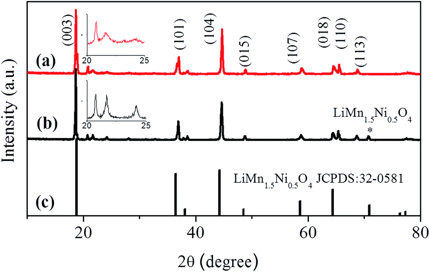 | ||
| Fig. 1 XRD patterns of Li1.2Mn0.54Ni0.13Co0.13O2 microspheres (a) and Li1.2Mn0.54Ni0.13Co0.13O2/LiNi0.5Mn1.5O4 microspheres (b). The standard card of pure LiMn1.5Ni0.5O4 is also exhibited in (c). The insets of (a) and (b) show the superlattices between 20° and 25° of the pristine and coated Li1.2Mn0.54Ni0.13Co0.13O2 cathode materials, respectively. | ||
To further investigate the microstructure of the uncoated Li1.2Mn0.54Ni0.13Co0.13O2 and coated Li1.2Mn0.54Ni0.13Co0.13O2/LiNi0.5Mn1.5O4 cathode materials, TEM and HRTEM examinations were conducted. Fig. 2a and d show the low-magnification images of the uncoated Li1.2Mn0.54Ni0.13Co0.13O2 and coated Li1.2Mn0.54Ni0.13Co0.13O2/LiNi0.5Mn1.5O4 composites, which indicate that the products remain spherical and the diameter of the microsphere is about 4 μm. As marked in Fig. 2d, the outer shell of LiNi0.5Mn1.5O4 adheres to the inner core of Li1.2Mn0.54Ni0.13Co0.13O2 uniformly with an average thickness of about 300 nm. Fig. 2b and c show the HRTEM images of the pristine material Li1.2Mn0.54Ni0.13Co0.13O2. There are two kinds of crystal lattice in the image: one lattice fringe width was 0.47 nm, corresponding to the (003) plane, and the other one was 0.238 nm, corresponding to the (006) plane of Li1.2Mn0.54Ni0.13Co0.13O2. Fig. 2e and f illustrate the details of the HRTEM images of the coated materials; the lattice fringe width was 0.47 nm, corresponding to the (111) plane of LiNi0.5Mn1.5O4.
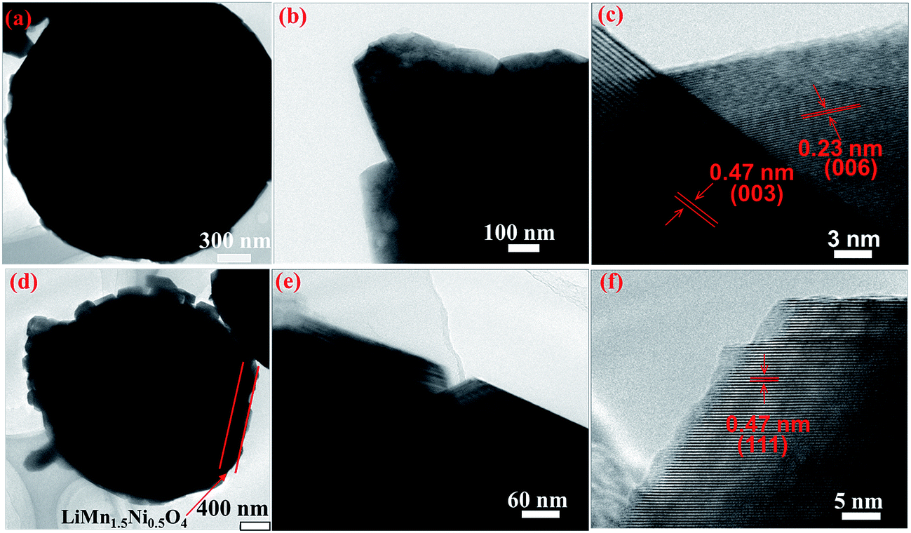 | ||
| Fig. 2 (a–c) TEM images of the uncoated Li1.2Mn0.54Ni0.13Co0.13O2; (d–f) TEM images of the coated Li1.2Mn0.54Ni0.13Co0.13O2/LiNi0.5Mn1.5O4 microsphere cathode; (b) and (c) are HRTEM images of Li1.2Mn0.54Ni0.13Co0.13O2; (e) and (f) are HRTEM images of the Li1.2Mn0.54Ni0.13Co0.13O2/Li Ni0.5Mn1.5O4 material. | ||
Fig. 3a shows the SEM image of the coated Li-rich Li1.2Mn0.54Ni0.13Co0.13O2 with the corresponding EDX spectra of the interior part (Fig. 3b) and outer surface (Fig. 3c). The estimated Ni:Co:Mn atomic ratios are 0.13(4):0.11(2):0.54(0) (the interior part) and 1:0:4.6(9) (the outer surface), as shown in Fig. 3b and c. In fact, the atomic ratios may hardly be indicative of the chemical composition of each Li-rich manganese-based compound, but the selected zone can reflect well the existence of the expected elements of the prepared spherical product, and there is no Co element in the outer layer.
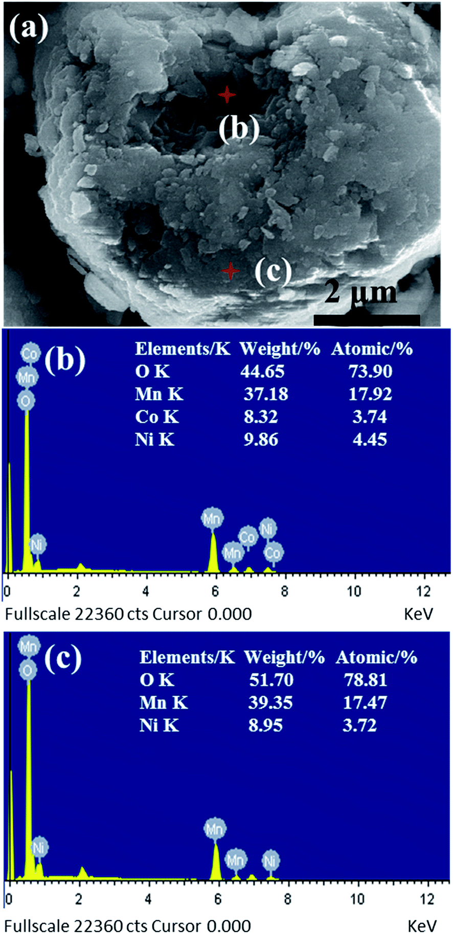 | ||
| Fig. 3 To discuss the difference in elementary composition between the outer layer and the internal composite, we made an energy spectrum spot measurement in a cracked granulocyte. (a) SEM image of the selected cracked granulocyte (test spots are marked); EDX spectra showing (b) the internal spot and (c) the outer layer element content. | ||
To explore the advantages of the current Li1.2Mn0.54Ni0.13Co0.13O2/LiNi0.5Mn1.5O4 composites as cathode active materials for high voltage Li-ion batteries, a coin cell was assembled using Li1.2Mn0.54Ni0.13Co0.13O2/LiNi0.5Mn1.5O4 as the cathode material and Li metal as the counter electrode. For comparison, the pristine Li1.2Mn0.54Ni0.13Co0.13O2 was also studied. The cells were cycled between 2.0 V and 4.8 V at room temperature. Fig. 4a shows the first charge and discharge curves of the pristine and coated materials at a rate of 0.2C (1C is equal to a current density of 300 mA g−1). The coated Li1.2Mn0.54Ni0.13Co0.13O2/LiNi0.5Mn1.5O4 composite electrode delivered an initial discharge capacity of 225 mA h g−1, which is larger than the pristine composite Li1.2Mn0.54Ni0.13Co0.13O2 (202 mA h g−1). In addition, they both exhibit a long plateau on the charge curve which corresponds to the removal of Li-ions from the Li2MnO3 component accompanied by oxygen evolution.11 As can be seen, the long plateau of the coated composite is relatively longer than that of the pristine one, which may be the reason for the higher specific capacity of the coated materials. The discharge voltage (Fig. 4a) of the coated electrode was apparently higher than that of the pristine electrode, suggesting the higher energy density of the battery.
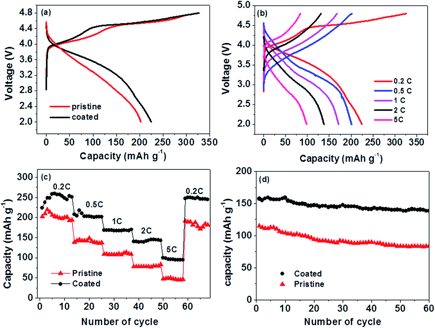 | ||
| Fig. 4 Electrochemical performances of the pristine Li1.2Mn0.54Ni0.13Co0.13O2 and coated Li1.2Mn0.54Ni0.13Co0.13O2/LiNi0.5Mn1.5O4 cathode materials: (a) the first charge and discharge curves of the pristine and coated Li-rich cathodes; (b) charge and discharge curves of Li1.2Mn0.54Ni0.13Co0.13O2/LiNi0.5Mn1.5O4 microspheres at different rates; (c) discharge capacity comparison of the pristine (red) and coated (black) Li-rich cathodes at different rates; (d) the long cycle performance of the pristine (red) and coated (black) Li-rich cathodes at a high current density of 1C. | ||
Fig. 4b presents the charge and discharge curves of the Li1.2Mn0.54Ni0.13Co0.13O2/LiMn1.5Ni0.5O4 coated microspheres at different rates. They delivered an average capacity of 221, 202, 168, 142 and 95 mA h g−1 at a current density of 0.2C, 0.5C, 1C, 2C and 5C, respectively. After cycling at different rates, the cell was cycled back to a current density of 60 mA g−1, and its discharge capacity was 245 mA h g−1 (Fig. 4c). In contrast, the pristine Li-rich Li1.2Mn0.54Ni0.13Co0.13O2 composite delivered a capacity of 205, 142, 108, 77, and 48 mA h g−1, at a current density of 0.2C, 0.5C, 1C, 2C and 5C, respectively. For the initial few cycles, the discharge capacities of both composites increased at a current density of 60 mA g−1, which might be caused by activation of the cathode material while cycling. The variation of the discharge capacity as a function of the cycle number was performed to evaluate the capacity retention of the as-prepared Li-rich cathode materials. Fig. 4d demonstrates a comparison of the cycling performance between the conventional uncoated and coated Li-rich cathode materials at a rate of 1C. The coated cathode shows much better cycling stability with 87.7% capacity retention after 60 cycles, while the pristine one maintains 72.2% of its initial capacity.
With a coating layer of LiMn1.5Ni0.5O4, the high voltage Li1.2Mn0.54Ni0.13Co0.13O2/LiNi0.5Mn1.5O4 cathode shows better rate capacity and cycling stability. Fig. 5a and b display the differential capacity versus voltage of the pristine and coated cathodes for the first charging process corresponding to the charging curves of Fig. 4a. The coin cells were cycled between 2.0 V and 4.8 V at a current density of 0.2C. Both the uncoated and coated electrodes exhibited two distinct and one weak dQ/dV peak; the weak peak is from 3.7 V to 4.25 V and one strong peak is from 4.25 V to 4.6 V. The much larger anodic peak at 4.5 V corresponds to the irreversible reaction in which the Li is extracted from the Li2MnO3 component with the simultaneous release of oxygen. As for the second strong peak occurring at about 4.74 V, this corresponds to the oxidation of Ni2+/Ni3+ and Ni3+/Ni4+ for the LiMn1.5Ni0.5O4 ingredient.27 After the cells were charged/discharged for 20 cycles, their EIS spectra were recorded (Fig. 5c). The Nyquist plots show a high frequency semicircle and a low frequency line inclined at a constant angle to the real axis. The semicircle indicates the double-layer response at the electrode/sample interface and the line shows the diffusion of Li-ions in the solid matrix.22 It is clear that the resistance of the coated cathode is much smaller than that of the pristine one. According to Chen et al. and our previous studies on the EIS of Li-ion batteries,35–37 cell impedance is mainly attributed to the cathode impedance, especially charge-transfer resistance. Therefore, it can be assumed that the electrochemical impedance of the coated composition is suppressed by the presence of LiMn1.5Ni0.5O4 and the discharge capacity of the coated material increased nearly 50 mA h g−1 at a current density of 0.2C.
 | ||
| Fig. 5 (a) The differential capacity versus voltage of the pristine composite cathode cycled between 2.0 V and 4.8 V for the first cycling process at a rate of 0.2C, (b) the differential capacity versus voltage of the coated composite cathode for the first cycling process at a rate of 0.2C, and (c) the Nyquist plots of the pristine (red) and coated (black) Li-rich cathodes after the batteries performed 20 cycles. | ||
4. Conclusion
A scalable synthesis of a high voltage Li1.2Mn0.54Ni0.13Co0.13O2/LiNi0.5Mn1.5O4 cathode has been successfully developed via a simple co-precipitation method. The coated cathode shows much better cycling behavior and rate capability compared with the pristine one. The improvement is mainly attributed to the protective LiNi0.5Mn1.5O4 surface layer not only acting as an excellent Li-ion conductor to increase the rate capability of Li1.2Mn0.54Ni0.13Co0.13O2, but also protecting against HF attack of the Li1.2Mn0.54Ni0.13Co0.13O2 in the electrolyte. This design provides a new approach for the development of advanced Li-ion batteries with high energy density, good rate performance and high open operating voltage.Acknowledgements
This work was financially supported by National Natural Science Foundation of China (11202177, 51202207).References
- J. B. Goodenough and K.-S. Park, J. Am. Chem. Soc., 2013, 135, 1167–1176 CrossRef CAS PubMed.
- A. Manthiram, J. Phys. Chem. Lett., 2011, 2, 176–184 CrossRef CAS.
- C. Fell, D. Lee, Y. Meng, J. Gallardo-Amores, E. Moran and M. Arroyo-de Dompablo, Energy Environ. Sci., 2012, 5, 6214–6224 CAS.
- B. Dunn, H. Kamath and J.-M. Tarascon, Science, 2011, 334, 928–935 CrossRef CAS PubMed.
- J. Deng, H. Ji, C. Yan, J. Zhang, W. Si, S. Baunack, S. Oswald, Y. Mei and O. G. Schmidt, Angew. Chem., Int. Ed., 2013, 125, 2382–2386 CrossRef PubMed.
- X. Liu, J. Zhang, W. Si, L. Xi, B. Eichler, C. Yan and O. G. Schmidt, ACS Nano, 2015, 9, 1198–1205 CrossRef CAS PubMed.
- W. Si, I. Mönch, C. Yan, J. Deng, S. Li, G. Lin, L. Han, Y. Mei and O. G. Schmidt, Adv. Mater., 2014, 26, 7973–7978 CrossRef CAS PubMed.
- X. Sun, W. Si, X. Liu, J. Deng, L. Xi, L. Liu, C. Yan and O. G. Schmidt, Nano Energy, 2014, 9, 168–175 CrossRef CAS PubMed.
- J. B. Goodenough and Y. Kim, Chem. Mater., 2009, 22, 587–603 CrossRef.
- S. K. Martha, J. Nanda, G. M. Veith and N. J. Dudney, J. Power Sources, 2012, 199, 220–226 CrossRef CAS PubMed.
- A. R. Armstrong, M. Holzapfel, P. Novák, C. S. Johnson, S.-H. Kang, M. M. Thackeray and P. G. Bruce, J. Am. Chem. Soc., 2006, 128, 8694–8698 CrossRef CAS PubMed.
- C. S. Johnson, N. Li, C. Lefief and M. M. Thackeray, Electrochem. Commun., 2007, 9, 787–795 CrossRef CAS PubMed.
- J.-S. Kim, C. S. Johnson, J. T. Vaughey, M. M. Thackeray, S. A. Hackney, W. Yoon and C. P. Grey, Chem. Mater., 2004, 16, 1996–2006 CrossRef CAS.
- M. M. Thackeray, S.-H. Kang, C. S. Johnson, J. T. Vaughey, R. Benedek and S. Hackney, J. Mater. Chem., 2007, 17, 3112–3125 RSC.
- J. Liu, T. Yang, D.-W. Wang, G. Q. Lu, D. Zhao and S. Z. Qiao, Nat. Commun., 2013, 4, 2798 Search PubMed.
- D. Mohanty, S. Kalnaus, R. A. Meisner, K. J. Rhodes, L. I. Jianlin, E. A. Payzant, D. L. Wood and C. Daniel, J. Power Sources, 2013, 229, 239–248 CrossRef CAS PubMed.
- B. Song, Z. Liu, M. O. Lai and L. Lu, Phys. Chem. Chem. Phys., 2012, 14, 12875–12883 RSC.
- S. H. Kang, P. Kempgens, S. Greenbaum, A. J. Kropf, K. Amine and M. M. Thackeray, J. Mater. Chem., 2007, 17, 2069–2077 RSC.
- K. Kumai, H. Miyashiro, Y. Kobayashi, K. Takei and R. Ishikawa, J. Power Sources, 1999, 81–82, 715–719 CrossRef CAS.
- L. Zeng, W. Zeng, Y. Jiang, X. Wei, W. Li, C. Yang, Y. Zhu and Y. Yu, Adv. Energy Mater., 2015, 5, 1401377 Search PubMed.
- J. Liu, Y. Wen, Y. Wang, P. A. van Aken, J. Maier and Y. Yu, Adv. Mater., 2014, 26, 6025–6030 CrossRef CAS PubMed.
- W. Liu, J. Liu, K. Chen, S. Ji, Y. Wan, Y. Zhou, D. Xue, P. Hodgson and Y. Li, Chem.–Eur. J., 2014, 20, 824–830 CrossRef CAS PubMed.
- Y. Wu, A. Vadivel Murugan and A. Manthiram, J. Electrochem. Soc., 2008, 155, A635–A641 CrossRef CAS PubMed.
- B. Liu, Q. Zhang, S. He, Y. Sato, J. Zheng and D. Li, Electrochim. Acta, 2011, 56, 6748–6751 CrossRef CAS PubMed.
- W. He, J. Qian, Y. Cao, X. Ai and H. Yang, RSC Adv., 2012, 2, 3423–3429 RSC.
- W. C. West, J. Soler, M. C. Smart, B. V. Ratnakumar, S. Firdosy, V. Ravi, M. S. Anderson, J. Hrbacek, E. S. Lee and A. Manthiram, J. Electrochem. Soc., 2011, 158, A883–A889 CrossRef CAS PubMed.
- E.-S. Lee, K.-W. Nam, E. Hu and A. Manthiram, Chem. Mater., 2012, 24, 3610–3620 CrossRef CAS.
- Y. Yu, Y. Shi, C.-H. Chen and C. Wang, J. Phys. Chem. C, 2008, 112, 4176–4179 CAS.
- C. Yan and D. Xue, J. Phys. Chem. B, 2006, 110, 11076–11080 CrossRef CAS PubMed.
- C. Yan, D. Xue, L. Zou, X. Yan and W. Wang, J. Cryst. Growth, 2005, 282, 448–454 CrossRef CAS PubMed.
- Z. Lu, L. Y. Beaulieu, R. A. Donaberger, C. L. Thomas and J. R. Dahn, J. Electrochem. Soc., 2002, 149, A778–A791 CrossRef CAS PubMed.
- J. M. Zheng, Z. R. Zhang, X. B. Wu, Z. X. Dong, Z. Zhu and Y. Yang, J. Electrochem. Soc., 2008, 155, A775–A782 CrossRef CAS PubMed.
- H. Deng, I. Belharouak, H. Wu, D. Dambournet and K. Amine, J. Electrochem. Soc., 2010, 157, A776–A781 CrossRef CAS PubMed.
- D.-K. Lee, S.-H. Park, K. Amine, H. Bang, J. Parakash and Y.-K. Sun, J. Power Sources, 2006, 162, 1346–1350 CrossRef CAS PubMed.
- J. Liu, W. Liu, S. Ji, Y. Wan, H. Yin and Y. Zhou, Eur. J. Inorg. Chem., 2014, 2014, 2073–2079 CrossRef CAS PubMed.
- J. Liu, W. Liu, S. Ji, Y. Wan, M. Gu, H. Yin and Y. Zhou, Chem.–Eur. J., 2014, 20, 5815–5820 CrossRef CAS PubMed.
- C. Chen, J. Liu and K. Amine, J. Power Sources, 2001, 96, 321–328 CrossRef CAS.
Footnote |
| † Electronic supplementary information (ESI) available. See DOI: 10.1039/c5ra17804e |
| This journal is © The Royal Society of Chemistry 2015 |