In situ preparation of novel heterojunction BiOBr/BiVO4 photocatalysts with enhanced visible light photocatalytic activity
Xiaobin Wu,
Hualei Zhou*,
Shaonan Gu,
Fangzhi Wang,
Jia Liu and
Wenjun Li
Beijing Key Laboratory for Science and Application of Functional Molecular and Crystalline Materials, University of Science and Technology Beijing, Beijing 100083, China. E-mail: hlzhou_ustb@163.com
First published on 19th October 2015
Abstract
Heterojunction photocatalysts BiOBr/BiVO4 were in situ synthesized through acid etching coupled with a hydrothermal process, and the optimized BiOBr/BiVO4 ratio was tuned to explore their visible-light photocatalytic activity for MB degradation. Remarkably, BiOBr/BiVO4 composites exhibited higher visible-light photocatalytic ability compared with single BiVO4 and BiOBr alone. The charge-separation process was interpreted based on the energy band structure. The heterojunction formed between BiVO4 and BiOBr, that effectively promotes the separation of photo-induced electrons and holes, is responsible for the improved photocatalytic activity.
1. Introduction
With the energy crisis and increasing environmental problems, green photocatalytic technology using solar energy exhibits great potential in degradation of organic pollutants. TiO2, as a traditional photocatalytic material, displays excellent photocatalytic activity, but responds only to ultraviolet light (less than 5% of solar energy) due to its large band gap. Despite tremendous efforts made to broaden the visible-light response range, its capability to utilize the solar energy is still unsatisfactory.1–3 To the end, the key to realize such purposes is designing and synthesizing new highly efficient visible-light photocatalysts. Fortunately, diverse visible-light responsive photocatalysts with a narrow band gap have been developed, such as WO3,4 BiVO4,5 Bi2WO6![[thin space (1/6-em)]](https://www.rsc.org/images/entities/char_2009.gif) 6 and Fe2O3,7 among which monoclinic bismuth vanadate (BiVO4) emerges as one of the most popular materials owing to its appropriate band gap (2.4 eV), chemical stability and environmentally friendly characteristics,8,9 and has experimentally demonstrated potential visible-light activity for the degradation of organic pollutants.10,11 The fast recombination of photo-induced electrons and holes, however, hinders its further gain when being employed alone. To solve this problem, one strategy is to manipulate the heterostructures by integrating BiVO4 with noble metal nanoparticles12 and/or other proper semiconductors with suitable band alignment such as BiVO4/Co3O4,13 Cu2O/BiVO4,14 BiIO4/BiVO4,15 BiVO4/g-C3N4
6 and Fe2O3,7 among which monoclinic bismuth vanadate (BiVO4) emerges as one of the most popular materials owing to its appropriate band gap (2.4 eV), chemical stability and environmentally friendly characteristics,8,9 and has experimentally demonstrated potential visible-light activity for the degradation of organic pollutants.10,11 The fast recombination of photo-induced electrons and holes, however, hinders its further gain when being employed alone. To solve this problem, one strategy is to manipulate the heterostructures by integrating BiVO4 with noble metal nanoparticles12 and/or other proper semiconductors with suitable band alignment such as BiVO4/Co3O4,13 Cu2O/BiVO4,14 BiIO4/BiVO4,15 BiVO4/g-C3N4![[thin space (1/6-em)]](https://www.rsc.org/images/entities/char_2009.gif) 16 etc. The charge carriers' recombination could be dramatically suppressed through the heterostructures, causing the higher carrier mobility and fast separation of electron–hole pairs.
16 etc. The charge carriers' recombination could be dramatically suppressed through the heterostructures, causing the higher carrier mobility and fast separation of electron–hole pairs.
Bismuth oxyhalides BiOX (X = Cl, Br, I) with a layered tetragonal matlockite crystal structure, were recently reported as efficient p-type photocatalysts for degrading pollutants.17–19 Interestingly, their band gaps decrease in the order of BiOCl, BiOBr, BiOI (∼3.2 eV, ∼2.7 eV, ∼1.7 eV, respectively20). BiOCl exhibited the exceptional photocatalytic property that was even higher than commercial P25 under UV irradiation. Nevertheless, it suffers the poor absorbency of solar energy as TiO2. BiOI presents the best visible-light photocatalytic activity, which was offset by the poor chemical stability and low oxidation activity. BiOBr simultaneously exhibits better visible-light absorbance and photocatalytic oxidation ability as well as chemical stability, and has received tremendous attention.21,22 BiOBr related heterostructures like BiOBr–CdS23 and BiOBr–BiOI24 all exhibited the excellent photocatalysis activity because of the unique layered feature of BiOBr and their efficient heterojunction structures. Given the band alignment agreement, it is highly expected that a p–n heterojunction between n-BiVO4 and p-BiOBr could benefit both the visible-light absorption and the separation of photo-induced carriers.
In this study, BiOBr/BiVO4 heterojunction photocatalysts were therefore synthesized for the first time by an in situ acid etching method using hydrobromic acid (HBr) as an etching agent. In situ preparation is a predominant approach in synthesizing composite materials, via which the intimate contact between two phases could be beneficial to the transfer and separation of photoinduced charges advantageous over the common deposition technologies.19,25 Their photocatalytic activities were evaluated by degrading MB under visible light (λ > 400 nm). The photocatalytic mechanism of BiOBr/BiVO4 heterojunction was proposed based on the energy band structures and the reactive species.
2. Experimental
2.1. Materials
All chemicals (analytical purity) were commercially available and used without further purification.2.2. Preparation of catalysts
BiVO4 precursor with hollow morphology and ring structure was achieved by a hydrothermal method reported in literature.14 Briefly, 7.5 mmol Bi(NO3)3·5H2O was dissolved in 3.3 M diluted nitric acid solution to get clear Bi(NO3)3 solution. Additionally, 7.5 mmol NH4VO3 and 1.5 g EDTA were dissolved in 15 mL of 4 M NaOH solution at 35 °C to get transparent NH4VO3 solution. Then, the prepared NH4VO3 solution was dropwised into the above Bi(NO3)3 solution under stirring to obtain a stable yellow suspension. After the pH value was slowly adjusted to 7 with 2 M NaOH aqueous solution, the suspension was transferred into a 50 mL Teflon-lined stainless steel autoclave and heated at 180 °C for 24 h. Finally, the product was centrifuged, washed with deionized water and ethanol, and dried at 80 °C in air to yield the BiVO4 precursor.Heterojunction photocatalysts BiOBr/BiVO4 were synthesized via a simple acid etching method in a hydrothermal process. 0.276 g of BiVO4 powder was dispersed in 80 mL of HBr solution (8.00 mM) and then vigorously stirred for 1 h. The attained mixture was transferred into a 100 mL Teflon-lined stainless steel autoclave and heated at 180 °C for different periods (17 h, 24 h, 31 h). The precipitates were centrifuged, washed with deionized water and dried at 80 °C in air to obtain BiOBr/BiVO4 heterojunction catalysts. In addition, single BiVO4 and BiOBr were prepared by repeating the hydrothermal process (180 °C, 24 h) except replacing HBr solution by deionized water and BiVO4 powder by 1 mmol Bi(NO3)3·5H2O, respectively.
2.3. Characterization of catalysts
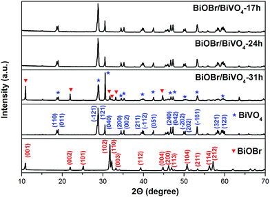
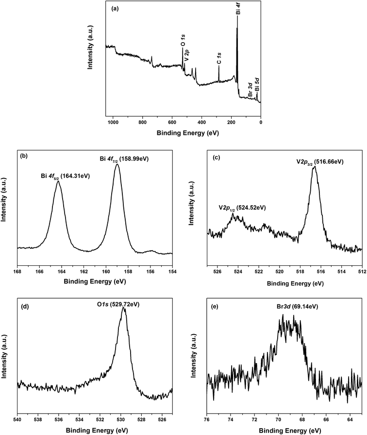
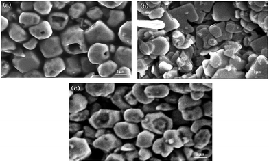
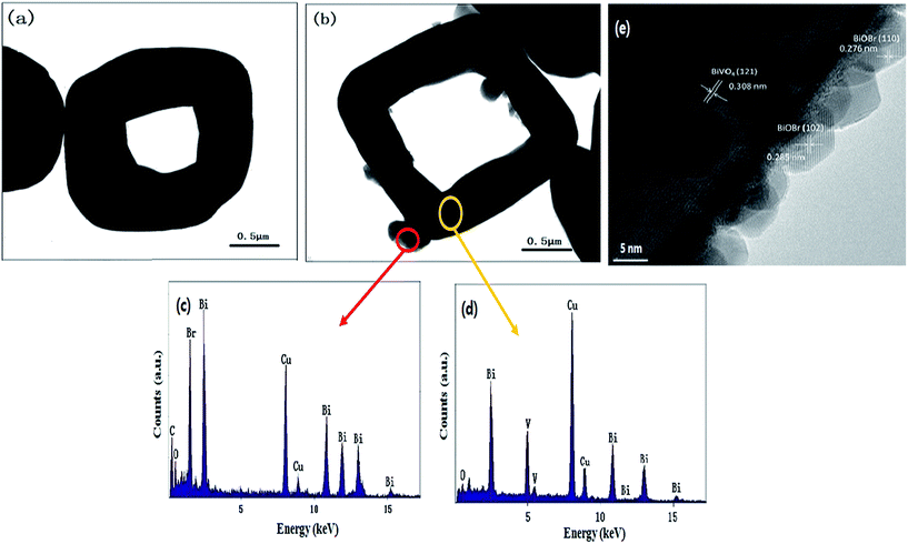
The crystal structures of the prepared samples were recorded by D/MAX-RB X-ray powder diffraction (XRD, Rigaku, Japan) with Cu Kα radiation (λ = 0.15405) at 40 kV and 30 mA. The morphologies and microstructures were observed by a scanning electron microscopy (SEM, JEOL JSM-6510A, Japan) at 5.00 kV and 10 mA, and a transmission electron microscopy (TEM, JEM-2100, Japan). The chemical status of Bi, O, V and Br was determined by a X-ray photoelectron spectroscopy (XPS, AXIS ULTRADLD, Kratos, Japan) with an Al Kα line. UV-vis diffuse reflectance spectra (DRS) were carried out on a U-3900H UV-vis spectrophotometer (Hitachi, Japan) equipped with an integrating sphere attachment in the 400–800 nm range. The photoluminescence (PL) spectra were detected using F-4500 fluorescence spectrophotometer (Hitachi, Japan) with the excitation wavelength of 278 nm.2.4. Photocatalytic activity measurements
The photocatalytic activities of as-prepared samples were estimated by the degradation of MB solution (10 mg L−1, neutral condition) under visible-light at room temperature. A 100 W incandescent lamp was used as the light source (with a cutoff filter (λ > 400 nm)). The distance between the light source and the reactor is fixed to be 5 cm. The suspension containing 50 mg photocatalyst sample in 50 mL MB aqueous solution was magnetically stirred for 1 h in the dark to reach an adsorption–desorption equilibrium before exposed to the light. At given irradiation time intervals of 1 h, 5 mL suspension was sampled and centrifuged. The concentration of supernatant was determined by Hitachi UV-vis spectrophotometer (U-3900H) at 664 nm. The degradation efficiency of MB was evaluated via the ratio of C/C0, where C was the concentration of MB during the reaction and C0 was the initial concentration.3. Results and discussion
3.1. Characterization of photocatalysts
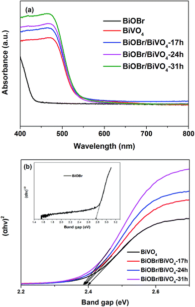
| αhv = A(hν − Eg)n/2, |
Clearly, BiOBr has an absorption edge at 450 nm, corresponding to a band gap of 2.76 eV; while BiVO4 exhibits better visible light absorption up to 516 nm. Compared with pure BiVO4, all BiOBr/BiVO4 heterojunctions exhibit higher visible light absorption ability. With increasing BiOBr content, the absorption intensity of BiOBr/BiVO4 enhanced gradually. All the BiOBr/BiVO4 series have a similar band gap of ∼2.38 eV, which was close to pure BiVO4.33,35 This means the increase in the light absorption mainly stems from the scattering effect due to the presence of tiny BiOBr on BiVO4.
3.2. Photocatalytic properties
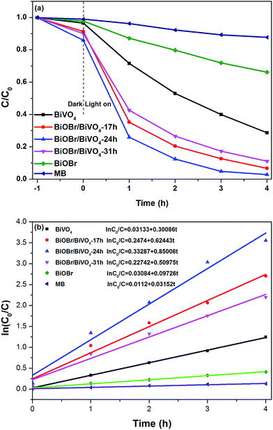 | ||
| Fig. 6 (a) Photocatalytic degradation efficiency of MB by as-prepared samples under visible light irradiation and (b) the kinetics of degradation of MB over different samples. | ||
In order to directly present the reaction kinetics of MB degradation, the photocatalytic process is quantitatively expressed using the pseudo-first-order kinetics equation:
| ln(C0/C) = kt + α, |
3.3. Possible photocatalytic mechanism
It is crucial for a heterojunction illustrating better photocatalytic performance that the each involved component must have a favorable band alignment with its counterparts. To understand the electronic band structure between BiVO4 and BiOBr, the CB and VB potentials of BiOBr and BiVO4 were estimated by the following empirical formulas,| ECB = χ − Ee − 0.5Eg | (1) |
| EVB = ECB + Eg | (2) |
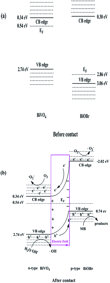 | ||
| Fig. 8 Schematic diagram: (a) the band edge positions of BiVO4 and BiOBr and (b) the possible reaction mechanism over BiOBr/BiVO4 heterojunction photocatalyst. | ||
When p-BiOBr and n-BiVO4 were brought together to form a p–n heterojunction, a depletion layer could be created at the interface that leads to the formation of an internal static electric field. Meanwhile, Fermi levels shift to reach an energetic equilibration. Owing to the low BiOBr content in the composites, the ultimate Fermi level of such heterojunction should approach to around 0.54 eV close to that of BiVO4. This means energy bands of BiOBr will move forward along the Fermi level and generate the band bending at the interface to generate a type II p–n heterojunction. A possible schematic band alignment diagram in such heterostructure is shown in Fig. 8b. On the one hand, BiOBr cannot block the visible light harvesting by BiVO4 because BiOBr is transparent for that wavelength range, instead improve the light absorption of BiVO4 due to scattering as demonstrated in Fig. 5a. On the other hand, both the band alignment between BiVO4 and BiOBr and the internal electric field at the interface are favorable for charge separation.
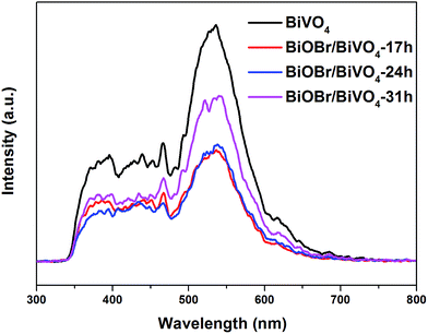
To confirm this effect, PL test was performed, as shown in Fig. 9. Generally, the relatively lower PL intensity means the lower recombination rate of electron–hole pairs and thus the higher photocatalytic activity. Clearly, the PL intensity of BiOBr/BiVO4 composites notably decrease compared with pure BiVO4, which demonstrates that the heterojunction formed between BiOBr and BiVO4 effectively improves the charge separation and suppresses the charge recombination.
Photocatalytic reaction includes four basic processes: light absorption, charge separation, migration, and recombination. The survived charge carriers (holes and electrons) diffuse to the surface and participate in the chemical reactions through generating reactive species ˙O2− and ˙OH, as well as h+, which ultimately photocatalytically degrade the organic substances. In order to confirm the function of three reactive species in this study, different scavengers, benzoquinone (BQ),39 isopropyl alcohol (IPA),40 and ammonium oxalate (AO),41 were employed to trap ˙O2−, ˙OH and h+, respectively. The corresponding ultimate concentrations of BQ, IPA and AO in the reaction were 0.3 mmol L−1, 1.0 mmol L−1 and 1.0 mmol L−1, respectively. Meanwhile, the experiment without scavenger was also performed. With adding any scavenger, the degradation rate declined (Fig. 10), which suggests that ˙O2−, ˙OH and h+ all played key roles in the MB degradation. Based on the experimental data, the function of active species decreased according to the following order: h+ > ˙O2− > ˙OH.
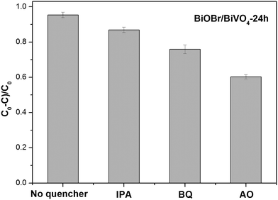 | ||
| Fig. 10 Trapping experiments of active species on the degradation of MB in the presence of BiOBr/BiVO4-24 h. | ||
As discussed above, a quantity of holes transferred to the VB of BiOBr. Since the VB (0.74 eV) of BiOBr is less positive than E(˙OH/OH−) (2.38 eV),32 however, the holes on the VB of BiOBr couldn't be able to oxidize OH−/H2O to ˙OH. Instead most of the photogenerated holes directly oxidized MB adsorbed on the surface of BiOBr/BiVO4 composites. This pathway predominates in degradation process of MB, which is consistent with the trapping experiment. While, the small quantity of holes in the VB of BiVO4 possessing strong oxidizing ability due to their high positive potential (2.74 eV) could oxidize OH− and H2O to ˙OH and then degrade MB. Furthermore, it is possible that the electrons in the VB of BiVO4 could be excited to the higher positions besides the bottom positions of the CB.41–44 These electrons could also reduce O2 to ˙O2− to degrade MB. Thus, h+, ˙O2− and ˙OH all contributed to the degradation but the function decrease in turn, which is consistent with trapping experiments well. A possible pathway of photocatalytic reaction can be proposed as follows:
| BiOBr/BiVO4 + hv → BiOBr/BiVO4 + e− + h+ | (3) |
| e− + O2 → ˙O2− | (4) |
| h+ + OH−/H2O → ˙OH | (5) |
| MB + h+/˙OH/˙O2− → products | (6) |
4. Conclusions
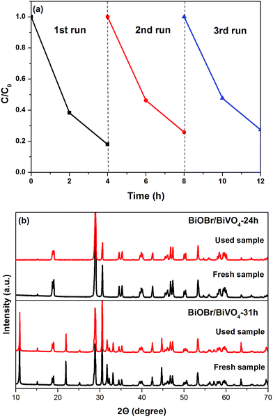
In summary, BiOBr/BiVO4 heterojunction photocatalysts were successfully synthesized using acid etching under hydrothermal condition. The XRD, XPS and morphological studies reveal that BiOBr tiny particles grew tightly on the surface of monoclinic BiVO4. The as-prepared BiOBr/BiVO4 composites displayed much higher photocatalytic activity than pure BiOBr and BiVO4 for MB removal under visible light irradiation (λ > 400 nm) and owned good photocatalytic stability. The enhanced photocatalytic activity of the composites is attributed to the formation of heterojunctions between BiOBr and BiVO4, which effectively improve the separation of photoinduced electron–hole pairs. Active species h+, ˙O2− and ˙OH all contribute to the degradation of MB.Acknowledgements
We gratefully acknowledge the financial support provided by the Project of the National Natural Science Foundation of China (Grant No. 21271022).References
- A. Naldoni, M. D'Arienzo, M. Altomare, M. Marelli, R. Scotti, F. Morazzoni, E. Selli and V. Dal Santo, Appl. Catal., B, 2013, 130, 239 CrossRef.
- Z. Ambrus, N. Balázs, T. Alapi, G. Wittmann, P. Sipos, A. Dombi and K. Mogyorósi, Appl. Catal., B, 2008, 81, 27 CrossRef CAS.
- K. E. DeKrafft, C. Wang and W. Lin, Adv. Mater., 2012, 24, 2014 CrossRef CAS PubMed.
- Y. Zang, L. Li, Y. Zuo, H. Lin, G. Li and X. Guan, RSC Adv., 2013, 3, 13646 RSC.
- S. Obregón, A. Caballero and G. Colón, Appl. Catal., B, 2012, 117, 59 CrossRef.
- Y. Geng, P. Zhang and S. Kuang, RSC Adv., 2014, 4, 46054 RSC.
- P. Cai, S.-M. Zhou, D.-K. Ma, S.-N. Liu, W. Chen and S.-M. Huang, Nano-Micro Lett., 2015, 7, 183 CrossRef.
- S. J. Hong, S. Lee, J. S. Jang and J. S. Lee, Energy Environ. Sci., 2011, 4, 1781 CAS.
- A. Zhang, J. Zhang, N. Cui, X. Tie, Y. An and L. Li, J. Mol. Catal. A: Chem., 2009, 304, 28 CrossRef CAS.
- J. Yin, S. Huang, Z. Jian, Z. Wang and Y. Zhang, Mater. Sci. Semicond. Process., 2015, 34, 198 CrossRef CAS.
- X. Gao, H. B. Wu, L. Zheng, Y. Zhong, Y. Hu and X. W. D. Lou, Angew. Chem., 2014, 126, 6027 CrossRef.
- W. Wang, S. Meng, M. Tan, L. Jia, Y. Zhou, S. Wu, X. Huang, Y. Liang and H. Shi, Appl. Phys. A, 2015, 118, 1347 CrossRef CAS.
- X. Dang, X. Zhang, X. Dong, W. Ruan, H. Ma and M. Xue, RSC Adv., 2014, 4, 54655 RSC.
- W. Wang, X. Huang, S. Wu, Y. Zhou, L. Wang, H. Shi, Y. Liang and B. Zou, Appl. Catal., B, 2013, 134, 293 CrossRef.
- H. Huang, L. Liu, Y. Zhang and N. Tian, RSC Adv., 2015, 5, 1161 RSC.
- N. Tian, H. Huang, Y. He, Y. Guo, T. Zhang and Y. Zhang, Dalton Trans., 2015, 44, 4297 RSC.
- Z. He, Y. Shi, C. Gao, L. Wen, J. Chen and S. Song, J. Phys. Chem. C, 2013, 118, 389 Search PubMed.
- F. Duo, Y. Wang, X. Mao, C. Fan and H. Zhang, Cryst. Res. Technol., 2014, 49, 721 CrossRef CAS.
- J. Cao, X. Li, H. Lin, S. Chen and X. Fu, J. Hazard. Mater., 2012, 239, 316 CrossRef PubMed.
- H. Cheng, B. Huang and Y. Dai, Nanoscale, 2014, 6, 2009 RSC.
- L. Ye, Y. Su, X. Jin, H. Xie and C. Zhang, Environ. Sci.: Nano, 2014, 1, 90 RSC.
- X. Zhang, Z. Ai, F. Jia and L. Zhang, J. Phys. Chem. C, 2008, 112, 747 CAS.
- Y. Guo, H. Huang, Y. He, N. Tian, T. Zhang, P. K. Chu, Q. An and Y. Zhang, Nanoscale, 2015, 7, 11702 RSC.
- H. Huang, X. Han, X. Li, S. Wang, P. K. Chu and Y. Zhang, ACS Appl. Mater. Interfaces, 2015, 7, 482 CAS.
- J. Hu, G. Xu, J. Wang, J. Lv, X. Zhang, Z. Zheng, T. Xie and Y. Wu, New J. Chem., 2014, 38, 4913 RSC.
- Q. Du, W. Wang, Y. Wu, G. Zhao, F. Ma and X. Hao, RSC Adv., 2015, 5, 31057 RSC.
- Z. Liu, B. Wu, Y. Zhu, D. Yin and L. Wang, Catal. Lett., 2012, 142, 1489 CrossRef CAS.
- J. Su, X.-X. Zou, G.-D. Li, X. Wei, C. Yan, Y.-N. Wang, J. Zhao, L.-J. Zhou and J.-S. Chen, J. Phys. Chem. C, 2011, 115, 8064 CAS.
- J. Zhang, J. Xia, S. Yin, H. Li, H. Xu, M. He, L. Huang and Q. Zhang, Colloids Surf., A, 2013, 420, 89 CrossRef CAS.
- L. Lu, L. Kong, Z. Jiang, H. H.-C. Lai, T. Xiao and P. P. Edwards, Catal. Lett., 2012, 142, 771 CrossRef CAS.
- L. Zhang, W. Wang, Z. Chen, L. Zhou, H. Xu and W. Zhu, J. Mater. Chem., 2007, 17, 2526 RSC.
- H. Cheng, B. Huang, Y. Dai, X. Qin and X. Zhang, Langmuir, 2010, 26, 6618 CrossRef CAS PubMed.
- S. Gu, W. Li, F. Wang, S. Wang, H. Zhou and H. Li, Appl. Catal., B, 2015, 170, 186 CrossRef.
- X. C. Song, W. T. Li, W. Z. Huang, H. Zhou, Y. F. Zheng and H. Y. Yin, Mater. Chem. Phys., 2015, 160, 251 CrossRef CAS.
- Z. S. Liu, B. T. Wu, J. N. Niu, P. Z. Feng and Y. B. Zhu, Mater. Res. Bull., 2015, 63, 187 CrossRef CAS.
- M. Long, W. Cai, J. Cai, B. Zhou, X. Chai and Y. Wu, J. Phys. Chem. B, 2006, 110, 20211 CrossRef CAS PubMed.
- J. Cao, X. Li, H. Lin, B. Xu, S. Chen and Q. Guan, Appl. Surf. Sci., 2013, 266, 294 CrossRef CAS.
- S. R. Morrison, Electrochemistry at Semiconductor and Oxidized Metal Electrodes, Plenum Press, New York, 1980 Search PubMed.
- J. Cao, B. Luo, H. Lin, B. Xu and S. Chen, J. Hazard. Mater., 2012, 217, 107 CrossRef PubMed.
- X. Zhang, T. Guo, X. Wang, Y. Wang, C. Fan and H. Zhang, Appl. Catal., B, 2014, 150, 486 CrossRef.
- H. Lin, H. Ye, S. Chen and Y. Chen, RSC Adv., 2014, 4, 10968 RSC.
- X. Zhang, L. Zhang, T. Xie and D. Wang, J. Phys. Chem. C, 2009, 113, 7371 CAS.
- L. Ye, J. Chen, L. Tian, J. Liu, T. Peng, K. Deng and L. Zan, Appl. Catal., B, 2013, 130, 1 Search PubMed.
- T. B. Li, G. Chen, C. Zhou, Z. Y. Shen, R. C. Jin and J. X. Sun, Dalton Trans., 2011, 40, 6751 RSC.
| This journal is © The Royal Society of Chemistry 2015 |

