
Fabrication of dual-mesoporous silica by triblock copolymers and metal-based ionic liquid: efficient and durable catalyst for oxidative desulfurization in fuel†
Lei Yanga,
Jun Xiongb,
Hongping Lia,
Ming Zhangb,
Wei Jiangb,
Hui Liua,
Wenshuai Zhu*b and
Huaming Li*ab
aSchool of Chemistry and Chemical Engineering, Jiangsu University, Zhenjiang 212013, P. R. China
bInstitute for Energy Research, Jiangsu University, Zhenjiang 212013, P. R. China. E-mail: zhuws@ujs.edu.cn; lhm@ujs.edu.cn; Fax: +86-511-88791708; Tel: +86-511-88791800
First published on 13th November 2015
Abstract
Dual-mesoporous silica was synthesized using the ionic liquid [C16mim]3PMo12O40 (1-hexadecyl-3-methylimidazolium phosphomolybdate) and the triblock copolymer P123 as co-templates. In this strategy, the ionic liquid [C16mim]3PMo12O40 was not only employed as the template, but also provided the metal source. The obtained catalysts were characterized by FTIR, Raman, XRD, XPS, N2 adsorption–desorption and utilized as catalysts to remove organic sulfur compounds from the model oil. The results demonstrated that compared with single channel silica, the catalysts with two uniform sets of mesopores showed higher catalytic performance for oxidative desulfurization. Dibenzothiophene (DBT) could be completely removed at 60 °C in 50 min. With regard to the refractory sulfur compound 4,6-dimethyldibenzothiophene (4,6-DMDBT), deep desulfurization could also be achieved. Moreover, the dual-mesoporous catalyst exhibited outstanding stability. It could be recycled for at least seven times without any activity decrease.
1. Introduction
One of the main challenges for present petroleum is to remove organic sulfur compounds in the fuel.1 Sulfur-containing compounds in fuel can be converted to SOx during combustion in car engines, which not only leads to acid rain, but also causes poisoning of the catalysts in automobile exhausts.2,3 Therefore, countries have implemented stringent standards for reducing the sulfur content in fuels.4 Hydrodesulfurization (HDS) is the main process for desulfurization in conventional petroleum refineries. But it still requires high temperature and high hydrogen pressure, and is less effective for removing aromatic organosulfur compounds including dibenzothiophene (DBT), benzothiophene (BT) and their alkyl derivatives.5 Hence, developing alternative and cost-effective technologies for desulfurization is highly desired.Currently, many other non-hydrodesulfurization processes, such as oxidative desulfurization (ODS),6–12 photocatalytic desulfurization,13–15 extractive desulfurization,16–19 and adsorptive desulfurization,3,20–23 have already emerged. Among these alternative desulfurization processes, ODS is a promising desulfurization technology because of its mild operating conditions (low temperature, atmospheric pressure), no hydrogen requirement, and high efficiency to remove aromatic organic sulfur compounds.24–26
Compared with homogeneous catalytic oxidative desulfurization systems, such as organic acids and a metallic catalyst,27,28 great interest has arisen in heterogeneous catalysis, due to outstanding properties in catalyst separation, selectivity, recovery and reuse. In previous work, many attempts have been made to immobilize catalytically active species on various supports. Mesoporous materials, owing to their high surface area, large pore volume, and easily modifiable surface, have attracted considerable interest and broad application in adsorption, catalysis, and carriers.29,30 Up to now, various kinds of mesoporous materials have been reported as supports for oxidative desulfurization catalysts, including MCM-41,6,31,32 SBA-15,1,33–36 mesoporous silica pillared clay,37,38 mesoporous silica,39–41 well-ordered hexagonal mesoporous silicate (HMS),42 mesoporous titania–silica,43 and mesoporous silica nanowires.44 The active species were usually supported on these mesoporous materials by surface functionalization, impregnation, and encapsulation of active moieties in the channels of the mesoporous materials. However, these methods have some drawbacks. Random distribution of active moieties may block the pores, an extra step is necessary to prepare the supported catalysts, and the single porous structure can result in poor mass transfer.
Dual-mesoporous materials with highly interconnected pore channels showed an enhanced accessibility and improved catalytic activity in reactions suffering from steric and/or diffusional limitations.45 Up to now, several different strategies have been developed for the synthesis of dual-mesoporous materials, such as the removal of framework atoms, dual templating with surfactants, and hard-templating methods.46–48 In this study, the triblock copolymer P123 and ionic liquid [C16mim]3PMo12O40 were used as co-templates for the fabrication of dual-mesoporous materials. The strategy is to build a dual-mesoporous material and use an in situ method to introduce the active species. As we know, ionic liquids (ILs) have been widely used for various fields. However, they have rarely been used as a co-template. In this procedure, the ionic liquid [C16mim]3PMo12O40 not only acted as a cationic surfactant, but also provided the metal source.
The motivation and aim of this work was the preparation of a dual-mesoporous material containing metal species with the IL [C16mim]3PMo12O40 as co-template and metal source. The as-prepared Mo containing dual-mesoporous material was applied as a catalyst for the removal of sulfur compounds in model oil. Compared with the single-mesoporous material, the dual-mesoporous material exhibited excellent catalytic activity. This synthesis procedure can be extended to a general strategy for synthesis of dual-mesoporous materials containing active centers and make heterogeneous catalysts with high activity.
2. Experimental
2.1. Materials
Dibenzothiophene (DBT), benzothiophene (BT), 4,6-dimethyldibenzothiophene (4,6-DMDBT) and the triblock copolymer P123 were purchased from Sigma-Aldrich. Commercially available tetraethyl orthosilicate (TEOS), 30 wt% H2O2, n-octane, para-xylene, cyclohexene, acetonitrile, tetradecane and H3PMo12O40·26H2O were bought from Sinopharm Chemical Reagent Co., Ltd. [C16mim]Cl was purchased from Shanghai Chengjie Chemical Co., Ltd.2.2. Catalyst preparation
![[thin space (1/6-em)]](https://www.rsc.org/images/entities/char_2009.gif) :1 and stirred at 40 °C for 12 h. The sediment was washed by purified water till the filtrate was neutral and dried. Then, the production [C16mim]3PMo12O40 was achieved and characterized by the 13C solid state NMR (Fig. S1†).
:1 and stirred at 40 °C for 12 h. The sediment was washed by purified water till the filtrate was neutral and dried. Then, the production [C16mim]3PMo12O40 was achieved and characterized by the 13C solid state NMR (Fig. S1†).For comparison, single-mesoporous MoO3–SiO2 was prepared under similar conditions as above with the amount of P123 as 2 g and the final product was denoted as S-MoO3–SiO2.
2.3. Characterization
Fourier transfer infrared spectra (FTIR) were recorded with a Nicolet Model Nexus 470 spectrometer using KBr pellets. Powder X-ray diffraction (XRD) was used for analyzing the crystalline phases of the catalysts using a Bruker D8 diffractometer with Cu Kα (λ = 1.54 Å) radiation. Raman spectra were obtained using a DXR Raman microscope with a 532 nm laser source. X-ray photoelectron spectroscopy (XPS) was carried out on a PHI 5600 multi-technique system with a monochromatic Al K R X-ray source (Physical Electronics). The surface area, pore volume and pore diameter of the samples were measured using a Brunauer–Emmett–Teller (BET) multipoint method and the adsorption branch of the isotherm. NMR spectra were obtained on a Bruker Advance 400 spectrometer. The morphology and structure of the samples were analyzed by field-emission scanning electron microscopy (SEM, JSM-7001F) and transmission electron microscopy (TEM, JEOL-JEM-2010) running at 200 kV.2.4. Oxidative desulfurization of model oil
Three types of model oil were prepared by dissolving DBT, BT and 4,6-DMDBT in n-octane with S-contents of 500, 500 and 216 ppm, respectively. The reaction of catalytic oxidative desulfurization was performed in a 20 mL two-necked flask with the experimental conditions of 0.01 g of catalyst, 0.234 mmol of H2O2 and 5 mL of the model oil at 60 °C. After the reaction, the remaining sulfur-containing compounds in the model oil were detected by a gas chromatography-flame ionization detector (GC-FID) with tetradecane as the internal standard (Agilent 7890A; HP-5, 30 m × 0.32 mm i.d. × 0.25 μm; FID: Agilent). The sulfur removal from the model oil was calculated by the following formula:where Co and Ct (mg L−1) were the initial sulfur concentration and the sulfur concentration at time t, respectively.

3. Results and discussion
3.1. Catalyst characterization
The FTIR spectra of the as-prepared samples are shown in Fig. 1. For D-MoO3–SiO2 and S-MoO3–SiO2, the absorption peaks at about 460, 805, 1086 cm−1 are attributed to the bending vibration, symmetric and asymmetric stretching vibration of Si–O–Si, respectively.33 The bands at 1632 cm−1 are ascribed to the bending of the hydroxyl stretch and physisorbed water.50 The stretching vibrations of Mo![[double bond, length as m-dash]](https://www.rsc.org/images/entities/char_e001.gif) O and Mo–O–Mo at 962, 882 cm−1 can also be seen,51 indicating that the Mo species were successfully introduced the mesoporous silica.
O and Mo–O–Mo at 962, 882 cm−1 can also be seen,51 indicating that the Mo species were successfully introduced the mesoporous silica.
 | ||
| Fig. 1 FTIR spectra of D-MoO3–SiO2 (a) and S-MoO3–SiO2 (b). | ||
The low-angle XRD patterns of D-MoO3–SiO2 and S-MoO3–SiO2 are presented in Fig. 2. Both D-MoO3–SiO2 and S-MoO3–SiO2 showed diffraction peaks in the range of 2θ = 1–3°, which suggests that the as-prepared materials were mesostructural. Fig. S2† shows the wide-angle XRD patterns of D-MoO3–SiO2 and S-MoO3–SiO2. As can be seen from the figure, except the characteristic amorphous SiO2 peak (wider diffraction peak at 25°), no remarkable other peaks were found on the wide-angle XRD patterns of the as-prepared materials. The results indicate that the Mo species was highly dispersed on the SiO2 matrix.
 | ||
| Fig. 2 Low-angle XRD patterns of D-MoO3–SiO2 (a) and S-MoO3–SiO2 (b). | ||
The chemical state of Mo was confirmed by Raman analysis. From the Raman spectra (Fig. 3), an intensive peak at 991 cm−1 corresponding to the MoO bond and a weak peak at approximately 824 cm−1 assigned to the O–Mo–O bond can be observed.52 Within the range of 200–400 cm−1, some characteristic peaks at 239, 338, and 374 cm−1 are visible and can be attributed to the different bending vibrational modes of MoO3.53 The results imply that the final condition of Mo was MoO3.
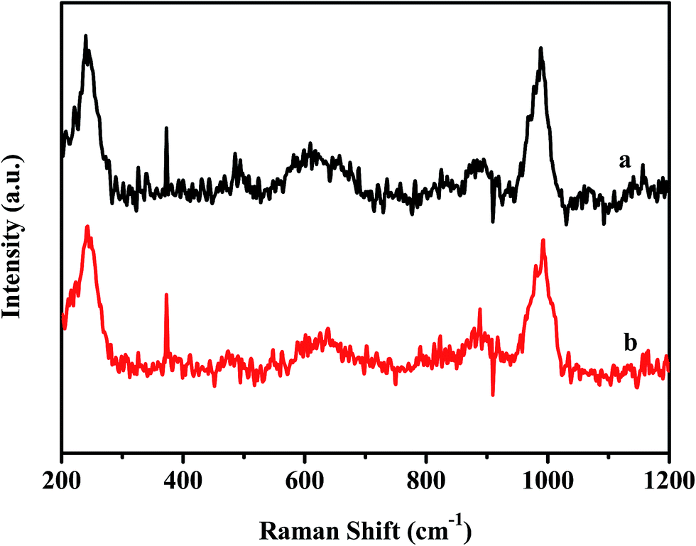 | ||
| Fig. 3 Raman spectra of D-MoO3–SiO2 (a), and S-MoO3–SiO2 (b). | ||
The surface composition and chemical states of the as-prepared D-MoO3–SiO2 were investigated by XPS analysis. Fig. 4a shows the survey spectrum of the material. The presence of elemental Mo, O, Si can be confirmed from the peaks at binding energies corresponding to Mo 3d, O 1s, Si 2p. The peak of C 1s was from carbon contamination. Fig. 4b presents the high resolution Mo 3d XPS spectrum of the sample. The two classic peaks of Mo 3d5/2 at 232.7 eV and Mo 3d3/2 at 235.7 eV ascribed to Mo6+ were observed.54 The Mo 3d and O 1s peaks indicated the existence of MoO3 in the sample. The UV-vis diffuse reflectance analysis is also provided to further determine the composition (Fig. 5). The samples showed two absorption bands at 233 and 314 nm, which is in agreement with the reported data on MoO3.55 The results of XPS and UV-vis diffuse reflectance analysis were consistent with the Raman characterization.
 | ||
| Fig. 4 X-ray photoelectron spectroscopy of D-MoO3–SiO2: (a) survey spectrum, (b) Mo 3d spectrum. | ||
 | ||
| Fig. 5 UV-vis diffuse reflectance spectra of D-MoO3–SiO2 (a), and S-MoO3–SiO2 (b). | ||
N2 adsorption–desorption isotherms were used to identify the structure of the catalysts (Fig. 6). The two as-prepared materials exhibited type-IV curves, indicating characteristic mesopores. From Fig. 6a, it can be observed that S-MoO3–SiO2 showed a distinct H2 type hysteresis loop, suggesting a uniform mesopore size distribution. While the desorption curve of D-MoO3–SiO2 showed two rapid drop at P/P0 = 0.4–0.6, indicating a bimodal-mesopore structure.56 The pore size distribution (PSD) was calculated using the Barrett–Joyner–Halenda model. S-MoO3–SiO2 displayed a very sharp PSD centered at 3.8 nm (Fig. 6b). The PSD curve of D-MoO3–SiO2 reflected sharp bimodal-mesopores with uniform sizes of 3.9 and 4.9 nm. The specific BET surface area and total pore volume of S-MoO3–SiO2 were 584 m2 g−1 and 0.64 cm3 g−1, respectively. D-MoO3–SiO2 had a bimodal-mesopore structure but with a relatively small specific BET surface area (478 m2 g−1) and total pore volume (0.56 cm3 g−1). It has been widely recognized that catalysts with larger specific surface areas can provide more active centers for contacting with reactants, which can lead to higher catalytic activity. In this system, the specific BET surface area of D-MoO3–SiO2 was lower than S-MoO3–SiO2, suggesting that the specific BET surface area was not the main factor influencing the catalytic performance of the catalysts.
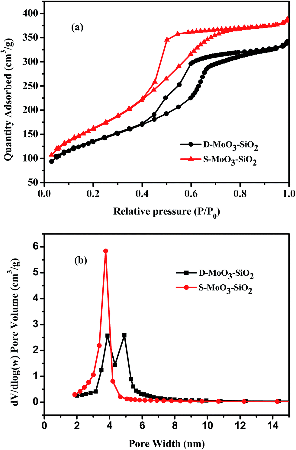 | ||
| Fig. 6 N2 adsorption–desorption isotherms (a) and pore size distribution curves (b) of the samples. | ||
SEM and TEM analysis were further performed to confirm the morphology and structure of the two materials. From the SEM images (Fig. S3†), it could be seen that the two materials all showed bulk texture without obvious difference. The TEM images are shown in Fig. 7. It can be seen that the two samples have mesoporous structures. However, D-MoO3–SiO2 showed two kinds of mesopores. One was ordered, the other was wormhole mesoporous. The result was consistent with the N2 adsorption–desorption isotherms analysis. As for S-MoO3–SiO2, it only showed the wormhole mesopores. In addition, it was noteworthy that the MoO3 particles could not be found in the TEM images, which proved the high dispersion of the active species. The results accorded well with the wide-angle XRD analysis.
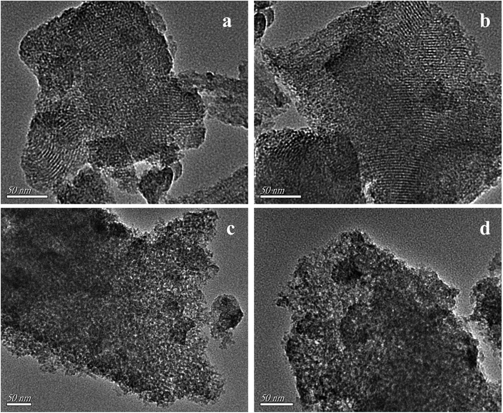 | ||
| Fig. 7 TEM images of D-MoO3–SiO2 (a and b) and S-MoO3–SiO2 (c and d). | ||
3.2. Catalysts for oxidative desulfurization
To explore their applicability, the as-prepared materials were used as catalysts for oxidative desulfurization. As shown in Fig. 8, D-MoO3–SiO2 exhibited excellent catalytic activity. The desulfurization efficiency could reach 100% in 50 min. S-MoO3–SiO2 was less active with 86.9% desulfurization efficiency within the same reaction period. When the time was prolonged to 90 min, the DBT was still not completely removed. Apparently, though both catalysts possessed the same chemical composition, D-MoO3–SiO2 revealed better catalytic activity than S-MoO3–SiO2. It was understood that a larger catalyst surface area could enhance the catalytic performance. S-MoO3–SiO2 had the larger surface area, while the poorer catalytic activity was observed. The result implied that a dual-mesoporous structure made a significant contribution to the catalytic oxidative desulfurization. Except that at 3.9 nm, D-MoO3–SiO2 possessed a larger pore size at 4.9 nm, which was beneficial to mass transfer for the larger molecules, like DBT. Therefore, the excellent pore accessibility of D-MoO3–SiO2 in the catalytic oxidative desulfurization system was proven. Moreover, a comparison of the most recently reported materials and D-MoO3–SiO2 used in oxidative desulfurization are listed in Table S1.† It was found that all of the catalysts show high catalytic performance for oxidative desulfurization in certain conditions. However, D-MoO3–SiO2 has advantages in the consumption of H2O2 and reaction time. Thus, D-MoO3–SiO2 should have potential in the field of oxidative desulfurization. | ||
| Fig. 8 Oxidative removal of DBT on the different catalysts D-MoO3–SiO2 and S-MoO3–SiO2. Experimental conditions: m (catalyst) = 0.01 g, n (H2O2) = 0.234 mmol, V (oil) = 5 mL, T = 60 °C. | ||
Besides DBT, there are also many different sulfur-containing compounds in real fuel, such as BT and 4,6-DMDBT. Thus, the catalytic performance of D-MoO3–SiO2 for BT and 4,6-DMDBT was also studied as shown in Fig. 9. It can be seen that the sulfur removal of the three sulfur-containing compounds decreased in the order of DBT > 4,6-DMDBT > BT under the same conditions. It has been reported that desulfurization performance decreased with the reduction of electron density on sulfur atoms.57 Among BT, DBT and 4,6-DMDBT, the electron density on the sulfur atom is 5.739, 5.758 and 5.760, respectively.6 The lowest electron density on the sulfur atom of BT resulted in the worst desulfurization efficiency. For DBT and 4,6-DMDBT, the electron density on the sulfur atom of 4,6-DMDBT (5.760) is slightly higher than that of DBT (5.758), but the sulfur removal of 4,6-DMDBT is lower than that of DBT owing to the effect of the steric hindrance of two methyl. Due to the steric hindrance of two methyl, 4,6-DMDBT is well recognized as a refractory sulfur compound and is difficult to remove efficiently in most reported literature.34,58 It was noted that 4,6-DMDBT could be removed completely in 70 min in this system. The enhanced catalytic oxidation activity for the removal of 4,6-DMDBT can be ascribed to the dual-mesoporous structure of the catalyst with interconnected pore channels, which can improve catalytic activity in reactions suffering from steric and/or diffusional limitations.
 | ||
| Fig. 9 Effect of sulfur-containing compounds on sulfur removal. Experimental conditions: m (D-MoO3–SiO2) = 0.01 g, n (H2O2) = 0.234 mmol, V (oil) = 5 mL, T = 60 °C. | ||
It is worth considering that the components in real fuel oil are complicated, such as aromatics, alkenes, etc. To investigate the effect of aromatics and alkenes on sulfur removal, 10 wt% para-xylene and 10 wt% cyclohexene as representative compounds were added to the model oil, respectively (Fig. 10). Compared with the model oil containing none, the desulfurization efficiency decreased slightly in the same conditions as the para-xylene was added, while a drastic reduction happened with the addition of cyclohexene. After 50 min of reaction, the final sulfur removal of DBT was 100%, 99.3% and 76.3% corresponding to the model oil containing none, 10 wt% para-xylene and 10 wt% cyclohexene, respectively. For cyclohexene, the exposed pi electrons are more sensitive to being attacked by H2O2 to form cycloalkane, and thus the cyclohexene played a strong negative effect on the removal of DBT. On the other hand, though the pi electrons of para-xylene exhibited relative stability, the α-hydrogen on the side-chain methyl groups is sensitive to being oxidized.5 Hence, the addition of a certain amount of para-xylene had a slightly negative impact on the removal of DBT. The results suggested that aromatics and alkenes in fuel oil have an inhibiting effect on ODS, owing to the competitive oxidation of these compounds and DBT on the D-MoO3–SiO2 catalyst with H2O2. At the same time, it was also indicated that alkene compounds may compete with DBT more intensively for catalytic oxidation sites on the D-MoO3–SiO2 catalyst than aromatic compounds.
 | ||
| Fig. 10 Effects of fuel composition on sulfur removal. Experimental conditions: m (D-MoO3–SiO2) = 0.01 g, n (H2O2) = 0.234 mmol, V (oil) = 5 mL, T = 60 °C. | ||
In order to investigate the stability and recyclability of D-MoO3–SiO2, the reusability of the catalyst was tested and the results are shown in Fig. 11. After each reaction, the catalyst was separated easily by decanting the model oil from a two-neck flask, dried in a vacuum oven at 80 °C overnight, and then used for a subsequent reaction by adding fresh H2O2 and model oil. As shown in Fig. 11, the catalyst could be reused seven times without any obvious reduction of catalytic activity. In addition, N2 adsorption–desorption analysis was used again to check the presence of the dual pores after sulfur removal. It could be found the bimodal-mesopore structure of D-MoO3–SiO2 still remained from the PSD curves (Fig. S4†). The results suggested that D-MoO3–SiO2 exhibited excellent stability and remarkable recyclability.
 | ||
| Fig. 11 Recycle times on removal of DBT with D-MoO3–SiO2 as catalyst. Experimental conditions: m (catalyst) = 0.01 g, n (H2O2) = 0.234 mmol, V (oil) = 5 mL, T = 60 °C, t = 60 min. | ||
4. Conclusions
In summary, a novel dual-mesoporous material D-MoO3–SiO2 was synthesized successfully using the ionic liquid [C16mim]3PMo12O40 and triblock copolymer P123 as co-templates. In this route, [C16mim]3PMo12O40 worked as the soft template and active component source at the same time which was superior to the impregnation method. The synthesized dual-mesoporous material was first applied to oxidative desulfurization exhibiting excellent catalytic performance due to its two uniform sets of mesopores facilitating mass transfer. The catalyst possessed favorable stability and could be recycled and reused at least seven times with barely any decrease in performance because of the unique dual-mesoporous structure. In addition, it is expected that many more dual-mesoporous materials like WOx/SiO2, MoO3/TiO2 and WOx/TiO2 can be explored for the application of oxidative desulfurization by the current strategy.Acknowledgements
This work was financially supported by the National Nature Science Foundation of China (No. 21276117, 21376111, 21406092), the State Key Laboratory of Heavy Oil Processing (SKLOP201402004) and A Project Funded by the Priority Academic Program Development of Jiangsu Higher Education Institutions (PAPD).References
- K. S. Cho and Y. K. Lee, Appl. Catal., B, 2014, 147, 35 CrossRef CAS.
- P. S. Kulkarni and C. A. M. Afonso, Green Chem., 2010, 12, 1139 RSC.
- J. Xiong, W. S. Zhu, H. P. Li, W. J. Ding, Y. H. Chao, P. W. Wu, S. H. Xun, M. Zhang and H. M. Li, Green Chem., 2015, 17, 1647 RSC.
- F. S. Mjalli, O. U. Ahmed, T. Al-Wahaibi, Y. Al-Wahaibi and I. M. AlNashef, Rev. Chem. Eng., 2014, 30, 337 CAS.
- J. Xiao, L. M. Wu, Y. Wu, B. Liu, L. Dai, Z. Li, Q. B. Xia and H. X. Xi, Appl. Energy, 2014, 113, 78 CrossRef CAS.
- J. Xiong, W. S. Zhu, H. M. Li, Y. H. Xu, W. Jiang, S. H. Xun, H. Liu and Z. Zhao, AIChE J., 2013, 59, 4696 CrossRef CAS.
- B. Y. Zhang, Z. X. Jiang, J. Li, Y. N. Zhang, F. Lin, Y. Liu and C. Li, J. Catal., 2012, 287, 5 CrossRef CAS.
- W. H. Wang, G. Li, W. G. Li and L. P. Liu, Chem. Commun., 2011, 47, 3529 RSC.
- E. Torres-García, A. Galano and G. Rodriguez-Gattorno, J. Catal., 2011, 282, 201 CrossRef.
- W. H. Lo, H. Y. Yang and G. T. Wei, Green Chem., 2003, 5, 639 RSC.
- H. Y. Lü, P. C. Li, C. L. Deng, W. Z. Ren, S. N. Wang, P. Liu and H. Zhang, Chem. Commun., 2015, 51, 10703 RSC.
- W. S. Zhu, P. W. Wu, L. Yang, Y. H. Chang, Y. H. Chao, H. M. Li, Y. Q. Jiang, W. Jiang and S. H. Xun, Chem. Eng. J., 2013, 229, 250 CrossRef CAS.
- W. S. Zhu, C. Wang, H. P. Li, P. W. Wu, S. H. Xun, W. Jiang, Z. G. Chen, Z. Zhao and H. M. Li, Green Chem., 2015, 17, 2464 RSC.
- F. Lin, D. E. Wang, Z. X. Jiang, Y. Ma, J. Li, R. G. Li and C. Li, Energy Environ. Sci., 2012, 5, 6400 CAS.
- C. Wang, W. S. Zhu, Y. H. Xu, H. Xu, M. Zhang, Y. H. Chao, S. Yin, H. M. Li and J. G. Wang, Ceram. Int., 2014, 40, 11627 CrossRef CAS.
- J. J. Gao, H. Meng, Y. Z. Lu, H. X. Zhang and C. X. Li, AIChE J., 2013, 59, 948 CrossRef CAS.
- A. Bösmann, L. Datsevich, A. Jess, A. Lauter, C. Schmitz and P. Wasserscheid, Chem. Commun., 2001, 2494 RSC.
- C. P. Li, D. Li, S. S. Zou, Z. Li, J. M. Yin, A. L. Wang, Y. N. Cui, Z. L. Yao and Q. Zhao, Green Chem., 2013, 15, 2793 RSC.
- W. Jiang, W. S. Zhu, H. P. Li, X. Wang, S. Yin, Y. H. Chang and H. M. Li, Fuel, 2015, 140, 590 CrossRef CAS.
- J. Xiong, W. S. Zhu, H. P. Li, L. Yang, Y. H. Chao, P. W. Wu, S. H. Xun, W. Jiang, M. Zhang and H. M. Li, J. Mater. Chem. A, 2015, 3, 12738 CAS.
- J. Xiong, W. S. Zhu, W. J. Ding, P. Wang, Y. H. Chao, M. Zhang, F. X. Zhu and H. M. Li, RSC Adv., 2014, 4, 40588 RSC.
- J. Xiao, X. X. Wang, M. Fujii, Q. J. Yang and C. S. Song, AIChE J., 2013, 59, 1441 CrossRef CAS.
- P. Tan, J. X. Qin, X. Q. Liu, X. Q. Yin and L. B. Sun, J. Mater. Chem. A, 2014, 2, 4698 CAS.
- W. S. Zhu, B. L. Dai, P. W. Wu, Y. H. Chao, J. Xiong, S. H. Xun, H. P. Li and H. M. Li, ACS Sustainable Chem. Eng., 2015, 3, 186 CrossRef CAS.
- P. W. Wu, W. S. Zhu, A. M. Wei, B. L. Dai, Y. H. Chao, C. F. Li, H. M. Li and S. Dai, Chem.–Eur. J., 2015, 21, 15421 CrossRef CAS.
- P. W. Wu, W. S. Zhu, Y. H. Chao, J. S. Zhang, P. F. Zhang, H. Y. Zhu, C. F. Li, Z. G. Chen, H. M. Li and S. Dai, Chem. Commun., 2015 10.1039/c5cc07830j.
- W. H. Lo, H. Y. Yang and G. T. Wei, Green Chem., 2003, 5, 639 RSC.
- W. Trakarnpruk and K. Rujiraworawut, Fuel Process. Technol., 2009, 90, 411 CrossRef CAS.
- Y. H. Deng, D. W. Qi, C. H. Deng, X. M. Zhang and D. Y. Zhao, J. Am. Chem. Soc., 2008, 130, 28 CrossRef CAS PubMed.
- J. Wei, Q. Yue, Z. K. Sun, Y. H. Deng and D. Y. Zhao, Angew. Chem., Int. Ed., 2012, 51, 6149 CrossRef CAS PubMed.
- R. Wang, Y. H. Li, B. S. Guo and H. W. Sun, Energy Fuels, 2011, 25, 3940 CrossRef CAS.
- Z. E. A. Abdalla and B. S. Li, Chem. Eng. J., 2012, 200–202, 113 CrossRef CAS.
- W. J. Ding, W. S. Zhu, J. Xiong, L. Yang, A. M. Wei, M. Zhang and H. M. Li, Chem. Eng. J., 2015, 266, 213 CrossRef CAS.
- J. Xiong, W. S. Zhu, W. J. Ding, L. Yang, M. Zhang, W. Jiang, Z. Zhao and H. M. Li, RSC Adv., 2015, 5, 16847 RSC.
- J. Xiong, W. S. Zhu, W. J. Ding, L. Yang, Y. H. Chao, H. P. Li, F. X. Zhu and H. M. Li, Ind. Eng. Chem. Res., 2014, 53, 19895 CrossRef CAS.
- L. N. Yang, J. Li, X. D. Yuan, J. Shen and Y. T. Qi, J. Mol. Catal. A: Chem., 2007, 262, 114 CrossRef CAS.
- B. S. Li, Z. X. Liu, C. Y. Han, J. J. Liu, S. L. Zuo, Z. Y. Zhou and X. M. Pang, J. Mol. Catal. A: Chem., 2011, 348, 106 CrossRef CAS.
- B. S. Li, Z. X. Liu, J. J. Liu, Z. Y. Zhou, X. H. Gao, X. M. Pang and H. T. Sheng, J. Colloid Interface Sci., 2011, 362, 450 CrossRef CAS PubMed.
- Y. Chen and Y. F. Song, ChemPlusChem, 2014, 79, 304 CrossRef CAS.
- Y. Chen, S. Zhao and Y. F. Song, Appl. Catal., A, 2013, 466, 307 CrossRef CAS.
- M. Chamack, A. R. Mahjoub and H. Aghayan, Chem. Eng. J., 2014, 255, 686 CrossRef CAS.
- B. S. Li, W. Ma, J. J. Liu, C. Y. Han, S. L. Zuo and X. F. Li, Catal. Commun., 2011, 13, 101 CrossRef CAS.
- X. M. Yan, P. Mei, L. Xiong, L. Gao, Q. F. Yang and L. J. Gong, Catal. Sci. Technol., 2013, 3, 1985 CAS.
- J. Dou and H. C. Zeng, ACS Catal., 2014, 4, 566 CrossRef CAS.
- D. P. Serrano, J. M. Escola and P. Pizarro, Chem. Soc. Rev., 2013, 42, 4004 RSC.
- P. Kortunov, S. Vasenkov, J. Karger, R. Valiullin, P. Gottschalk, M. Fé Elía, M. Perez, M. Stöcker, B. Drescher, G. McElhiney, C. Berger, R. Gläser and J. Weitkamp, J. Am. Chem. Soc., 2005, 127, 13055 CrossRef CAS.
- K. Möller, B. Yilmaz, U. Müeller and T. Bein, Chem. Mater., 2011, 23, 4301 CrossRef.
- H. Y. Chen, J. Wydra, X. Y. Zhang, P.-S. Lee, Z. P. Wang, W. Fan and M. Tsapatsis, J. Am. Chem. Soc., 2011, 133, 12390 CrossRef CAS PubMed.
- M. Zhang, W. S. Zhu, H. M. Li, S. H. Xun, W. J. Ding, J. J. Liu, Z. Zhao and Q. Wang, Chem. Eng. J., 2014, 243, 386 CrossRef CAS.
- X. C. Shao, X. T. Zhang, W. G. Yu, Y. Y. Wu, Y. C. Qin, Z. L. Sun and L. J. Song, Appl. Surf. Sci., 2012, 263, 1 CrossRef CAS.
- S. L. Wang, Y. Z. Zhang, T. Chen and G. Y. Wang, J. Mol. Catal. A: Chem., 2015, 398, 248 CrossRef CAS.
- R. Nadimicherla, W. Chen and X. Guo, Mater. Res. Bull., 2015, 66, 140 CrossRef CAS.
- J. Adamiak, W. Tomaszewski and W. Skupiński, Catal. Commun., 2012, 29, 92 CrossRef CAS.
- L. L. Sui, Y. M. Xu, X. F. Zhang, X. L. Cheng, S. Gao, H. Zhao, Z. Cai and L. H. Huo, Sens. Actuators, B, 2015, 208, 406 CrossRef CAS.
- C. Lin, K. Tao, H. B. Yu, D. Y. Hua and S. H. Zhou, Catal. Sci. Technol., 2014, 4, 4010 CAS.
- X. F. Qian, J. M. Du, B. Li, M. Si, Y. S. Yang, Y. Y. Hu, G. X. Niu, Y. H. Zhang, H. L. Xu, B. Tu, Y. Tang and D. Y. Zhao, Chem. Sci., 2011, 2, 2006 RSC.
- W. S. Zhu, G. P. Zhu, H. M. Li, Y. H. Chao, Y. H. Chang, G. Y. Chen and C. R. Han, J. Mol. Catal. A: Chem., 2011, 347, 8 CrossRef CAS.
- W. S. Zhu, H. M. Li, X. Jiang, Y. S. Yan, J. D. Lu, L. N. He and J. X. Xia, Green Chem., 2008, 10, 641 RSC.
Footnote |
| † Electronic supplementary information (ESI) available. See DOI: 10.1039/c5ra17509g |
| This journal is © The Royal Society of Chemistry 2015 |