Polyimide (PI) high-quality polymer dielectric films with the features of anti-solvents and large-area consistency for field-effect transistors†
Yunze Li‡
a,
Deyang Ji‡b,
Huanli Dongb,
Jingze Li*a and
Wenping Hu*b
aState Key Laboratory of Electronic Thin Films and Integrated Devices, School of Microelectronics and Solid-State Electronics, University of Electronic Science and Technology of China, Chengdu 610054, China. E-mail: lijingze@uestc.edu.cn
bBeijing National Laboratory for Molecular Sciences, Key Laboratory of Organic Solids, Institute of Chemistry, Chinese Academy of Sciences, Beijing 100190, China. E-mail: huwp@iccas.ac.cn
First published on 6th October 2015
Abstract
In this work, the properties of polyimide (PI) as a dielectric film are systematically investigated. PI films are processed using a spin-coating method under various conditions. Subsequently, the leakage current, unit-area capacitance and morphologies of these films are characterized. Then the anti-solvent property is certified upon comparing the films before and after solvent treatment. Organic field-effect transistors based on PI dielectric films and pentacene active films show uniform performance distribution over a large area. Furthermore, a single crystal of 2,7-dihexyl-dibenzo[d,d′]thieno[3,2-b;4,5-b′]dithiophene (C6-DBTDT) is obtained on the PI film using a solution-processed method and exhibits good electrical properties with the highest mobility of 3 cm2 V−1 s−1 and Ion/Ioff > 105. It is believed that this kind of PI polymer dielectric film has potential applications in solution-processed, flexible and large-area organic electronics.
Introduction
Organic thin-film transistors as the indispensable components of integrated circuits have attracted extensive attention due to their irreplaceable superior features, such as low-cost, large-area processing and good compatibility with flexible substrates.1–4 Over the past two decades, remarkable progress has been made to improve the performance of organic field-effect transistors (OFETs), which have surpassed polycrystalline silicon and are promising for flexible, lightweight electronic applications, such as radio frequency identification devices, complementary circuits, displays and plastic electronics.5–7 Thereinto, the charge mobility of p-type8 organic thin-film FETs has reached up to 23.2 cm2 V−1 s−1 and n-type OFETs9 exhibit a mobility as high as 6 cm2 V−1 s−1. It has been acknowledged that the dielectric film plays a crucial role in achieving these high-performance organic devices.10 The roughness, surface energy and trap density of the dielectric film have directly influenced the morphology of the active layer and then further determined the transport of the charge carrier.11–13 In addition, an uneven dielectric location over a large area results in a wide distribution of the device performances, which is a handicap in the fabrication of qualified organic circuits.14At present, there are three kinds of dielectric in organic electronics: inorganic insulators, self-assembled monolayer (SAM) dielectrics and polymer dielectrics. The first one has a good chemical resistance and unique heat endurance. However, the process of manufacturing such inorganic dielectric films is always extremely complicated, expensive and incompatible with flexible substrates.15 The second one is often applied to prepare low-operating voltage, low-power dissipation devices. But the instability limits its practical application in large area organic electronics.16 The last one is a polymer insulator, which can be easily prepared using a solution-processed method and is compatible with flexible substrates.17–19 A number of polymer dielectrics, such as polymethyl methacrylate (PMMA), polystyrene (PS), polyvinyl alcohol (PVA) and so on, have been proposed to achieve high performance OFETs.20,21 Nevertheless, these polymer insulator films can be easily etched by conventional solvents and have poor heat endurance, which become limitations for their applications in integrated circuits.22,23 Therefore, it is necessary to introduce a new polymer dielectric that can endure this oppressive preparation process.
Polyimide (PI) is a good candidate for polymer dielectric films24–26 and in our work, we present a systematic study of this polymeric insulator. The leakage current, unit-area capacitance and the morphologies of these films are characterized. The anti-solvent property is certified upon comparing these films before and after organic solvent treatment. Large-area thin film OFET arrays show a uniform mobility and threshold voltage distribution. Furthermore, solution-processed single crystal OFETs based on 2,7-dihexyl-dibenzo[d,d′]thieno[3,2-b;4,5-b′]dithiophene (C6-DBTDT)27 are built on the PI films. Bottom-gate top-contact OFETs are constructed by manually gluing Au-films, and exhibit excellent electrical properties with the highest mobility up to 3 cm2 V−1 s−1 and Ion/Ioff > 105. It is believed that this kind of polymer insulator has potential applications in solution-processed organic electronics.
Experimental section
In this work, PI films were prepared via spin-coating onto indium tin oxide (ITO) substrates and all substrates were cleaned with deionized water, acetone, and isopropyl alcohol under ultrasound for 10 minutes, and then dried with quickly purged N2. The substrates were further cleaned in oxygen plasma for 5 minutes. PI precursor (polyimide acid, PAA) films were firstly spin-coated on ITO substrates at different speeds (2000 rpm, 4000 rpm, 6000 rpm and 8000 rpm) for 30 seconds. Then, these films were cross-linked to form solid PI films at an annealing temperature of 300 °C. After that, the morphology and thickness of these films were investigated using atomic force microscopy (AFM) in tapping mode.In order to measure the leakage current and unit-area capacitance of the PI films, devices with an ITO/PI/Au (100 nm) sandwich structure were fabricated. The specific capacitance as a function of the frequency based on the PI film was tested using an electrochemical method. The leakage current of PI was characterized using a Keithley 4200-SCS semiconductor analyzer. Bottom-gate top-contact OFETs were fabricated employing PI as the dielectric film, and a pentacene film as the active layer. First, an approximately 50 nm thick pentacene film was thermally evaporated at a base pressure of 2 × 10⁻³ Pa and at a rate of 0.1–0.3 Å s−1, then the devices were completed after the 20 nm Au electrode was deposited through a shadow mask, and tested using a Keithley 4200-SCS semiconductor analyzer in ambient atmosphere.
Alternatively, the PI films were immersed in acetone and isopropyl alcohol for 5 min, exposed to ultrasound for 5 min, and dried with quickly purged N2, and then the properties of these films were tested to check the anti-solvent property directly. Furthermore, C6-DBTDT was dissolved in the chlorobenzene solvent with a concentration of about 0.3 mg ml−1.27 Therefore, C6-DBTDT single crystals were obtained on the solvent treated PI films using a drop-casting method, then the OFETs based on single crystals were constructed by manually gluing Au-films, and characterized using a Keithley 4200-SCS semiconductor analyzer in ambient atmosphere.
Results and discussion
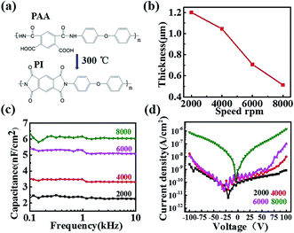
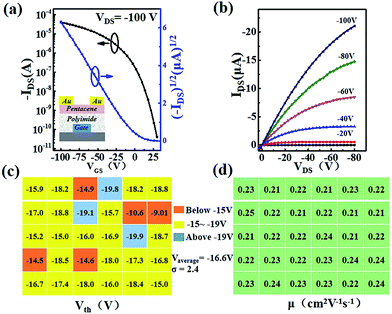
The chemical structures of PAA and PI are shown in Fig. 1a. The morphologies of these PI films with different spin speeds were characterized using AFM (Fig. 1S†). Smooth and compact PI films were observed and these films exhibited a root-mean-square roughness value of 0.21 ± 0.04 nm without major defects, such as pinholes or cracks, which was beneficial for the growth of the qualified semiconductors and enhancing the charge-transport at the interface. On the other hand, the thickness of the PI films varied from 1200 nm to 500 nm (Fig. 1b) with increasing coating speed from 2000 rpm to 8000 rpm, producing a capacitance per unit elevated from 2.3 nF cm−2 up to 6.1 nF cm−2 (Fig. 1c). At the same time, all of the PI films had a low leakage current density (Fig. 1d), which demonstrated their excellent insulating property.In order to confirm the applicability of the PI films as dielectric layers in organic electronics, bottom-gate top-contact OFETs (inset of Fig. 2a) were constructed with pentacene as the active layer and tested in ambient air. Here we discuss the experiment with the 4000 rpm prepared PI film as an example. The typical transfer characteristic of the device is shown in Fig. 2a, with a mobility extraction for the saturation region of 0.31 cm2 V−1 s−1 and an on/off ratio up to 9.9 × 10⁶, which was comparable with the results from previous reports.28,29 The output characteristic is shown in Fig. 2b. The device also showed the expected gate modulation of the drain current (ID) in both the linear and saturation regimes. Also, the devices fabricated with different thicknesses of PI films had perfect electronic properties (Fig. S2†). As is well known, an organic circuit is required to integrate identical transistors in quantity to realize a special function. Therefore, it is necessary to guarantee that the properties of the devices keep high stability and unification over a macroscopic area. In this work, the threshold voltages and mobilities of thirty randomly selected transistor devices have been recorded over a large area. As shown in Fig. 2c, the threshold voltage of 73.3% of the devices is between −15 V and −19 V, with an average voltage of −16.6 V and a standard deviation of 2.4, and the mobility (Fig. 2d) varies between 0.21–0.24 cm2 V−1 s−1. All of these data have directly proven the large-area uniformity of the PI films and that they could be applied to process large-area organic circuits in the future. Simultaneously, the morphologies of the pentacene films with different spinning speeds are characterized via AFM mapping (Fig. S3†). The pentacene films had a compact structure and showed good crystallinity. The average grain size was about 200 nm and the grains were arranged densely, which helps to obtain high performance devices. Subsequently, the n-type organic transistors based on N,N′-1H,1H-perfluorobutyl dicyanoperylenecarboxydiimide (PDIF-CN2) also had good electrical properties with a mobility of 2.45 × 10⁻⁶ cm2 V−1 s−1, an on/off ratio of 8.4 × 10² and a threshold voltage of −6 V in ambient atmosphere, where the output and transfer characteristics of the PDIF-CN2 OFETs are shown in Fig. S4.† All of these data have confirmed the applicability of the PI dielectric films in organic electronics.
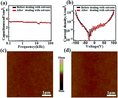
It is noted that the majority of polymer insulators are easily damaged by solvents, which prevents their applications for solution-processed techniques, such as photolithography and ink-jet printing.30–32 Here, anti-solvent measurements were done on the PI films. The capacitance (Fig. 3a) and leakage current density (Fig. 3b) of the PI films have no noticeable variation before and after solvent treatment. Moreover, there was no obvious change in the surface morphology before (Fig. 3c) and after (Fig. 3d) solvent treatment, illustrating that the solvents had not seriously damaged the surface structure as well as the bulk structure of the PI films. Subsequently, OFETs were constructed on the solvent treated PI films and showed good electrical properties (Fig. S5†), with an average mobility of 0.4 cm2 V−1 s−1 and Ion/Ioff up to 107, which are at the same level as those on the untreated PI films.
 | ||
| Fig. 3 (a) The capacitances and (b) leakage currents before and after solvent treatment; AFM images of the PI film before (c) and after (d) solvent treatment. | ||
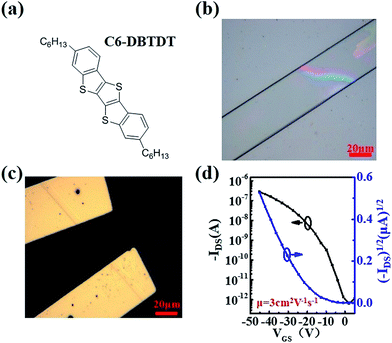
In order to demonstrate the wide applicability of the PI dielectric films, solution-processed C6-DBTDT (chemical structure shown in Fig. 4a) single crystals were prepared on the solvent treated PI films through a drop-casting method. As shown in the optical microscope image (Fig. 4b), the microribbon-like single crystal had a regular configuration and uniform color with a length over 100 μm. Then, the bottom-gate top-contact OFET (Fig. 4c) was constructed by manually gluing Au-films33–35 with PI as the dielectric and tested in ambient air. The typical transfer characteristic of the device is shown in Fig. 4d, with a mobility extraction for the saturation region of 3 cm2 V−1 s−1 and an on/off ratio up to 105.
Conclusions
In conclusion, PI as a dielectric film was processed using a spin-coating method under various conditions. The as-fabricated PI films had a very smooth surface and pin-hole free structure, leading to a negligible leakage current. Then, the anti-solvent property was excellent since the solvent treated PI films did not show noticeable changes concerning the surface morphology and the film structure. The thin film OFETs were constructed on both the solvent treated and untreated PI films with pentacene films as the active layers, illustrating uniform electric performance distribution even over a large area. Furthermore, the single crystal OFET of C6-DBTDT was obtained on the solvent treated PI film via a solution-processed method and exhibited good electrical properties with the highest mobility of 3 cm2 V−1 s−1 and Ion/Ioff > 105. It is believed that this kind of polymer insulator has great potential applications for the large-scale fabrication of solution-processed organic electronics.Acknowledgements
This work was partly supported by funding from the Science and Technology Bureau of Sichuan Province of China (No. 2015HH0033); the National Natural Science Foundation of China (No. 21473022, 51303185, 51222306, 61201105, 91222203, and 91233205); the Ministry of Science and Technology of China (2014CB643600); the Fundamental Research Funds for the Central Universities (No. ZYGX2012Z003); the China-Denmark Co-project, TRR61 (NSFC-DFG Transregio Project); and the Chinese Academy of Sciences.Notes and references
- S. Sun, L. F. Lan, P. Xiao, Z. G. Lin, H. Xu, M. Xu and J. B. Peng, RSC Adv., 2015, 5, 15695 RSC.
- Z. Ute, A. Frederik, Y. Tatsuya, T. Kazuo, K. Hirokazu, I. Masaaki, S. Tsuyoshi, S. Takao, K. Klaus and K. Hagen, Adv. Mater., 2010, 22, 982 CrossRef PubMed.
- D. Y. Ji, L. Jiang, Y. L. Guo, H. L. Dong, J. P. Wang, H. J. Chen, Q. Meng, X. L. Fu, G. F. Tian, D. Z. Wu, G. Yu, Y. Q. Liu and W. P Hu, Adv. Funct. Mater., 2014, 24, 3783 CrossRef CAS PubMed.
- X. Guo, S. R. Puniredd, B. He, T. Marszalek, M. Baumgarten, W. Pisula and K. Müllen, Chem. Mater., 2014, 26, 3595 CrossRef CAS PubMed.
- M. C. Ma, X. J. Xu, L. L. Shi and L. Li, RSC Adv., 2014, 4, 58720 RSC.
- L. Jiang, H. L. Dong and W. P. Hu, J. Mater. Chem., 2010, 20, 4994 RSC.
- B. He, A. B. Pun, D. Zherebetskyy, Y. Liu, F. Liu, L. M. Klivansky, A. M. McGough, B. A. Zhang, K. Lo, T. P. Russell, L. W. Wang and Y. Liu, J. Am. Chem. Soc., 2014, 136, 15093 CrossRef CAS PubMed.
- C. H. Wang, C. Y. Hsieh and J. C. Hwang, Adv. Mater., 2011, 23, 1630 CrossRef CAS PubMed.
- T. D. Anthopoulos, B. Singh, N. Marjanovic, N. S. Sariciftci, A. M. Ramil, H. Sitter, M. Colle and D. M. Leeuw, Appl. Phys. Lett., 2006, 89, 213504 CrossRef PubMed.
- C. Kim, A. Facchetti and T. J. Marks, Adv. Mater., 2007, 19, 2561 CrossRef CAS PubMed.
- W. Y. Chou, T. Y. Ho, H. L. Cheng, F. C. Tang, J. H. Chen and Y. W. Wang, RSC Adv., 2013, 3, 20267 RSC.
- M. Jang, Y. C. Yu, H. Jeon, J. H. Youk and H. Yang, ACS Appl. Mater. Interfaces, 2015, 7, 274 Search PubMed.
- B. He, J. Dai, D. Zherebetskyy, T. L. Chen, B. A. Zhang, S. J. Teat, Q. C. Zhang, L. W. Wang and Y. Liu, Chem. Sci., 2015, 6, 3180 RSC.
- D. Y. Khim, H. Han, K. J. Baeg, J. Kim, S. W. Kwak, D. Y. Kim and Y. Y. Noh, Adv. Mater., 2013, 25, 4302 CrossRef CAS PubMed.
- B. Crone, A. Dodabalapur, Y. Y. Lin, R. W. Filas, Z. N. Bao, A. Laduca, R. Sarpeshkar, H. E. Katz and W. Li, Nature, 2000, 403, 521 CrossRef CAS PubMed.
- M. Halik, H. Klauk, U. Zschieschang, G. Schmid, C. Dehm, M. Schutz and S. Maisch, et al., Nature, 2004, 43, 963 CrossRef PubMed.
- E. K. Lee, J. K. Kim, J. W. Chung, B. L. Lee and Y. Kang, RSC Adv., 2014, 4, 293 RSC.
- M. E. Roberts, N. Queralto, C. B. M. Stefan, N. R. Benjamin, W. Knoll and Z. N. Bao, Chem. Mater., 2009, 21, 2292 CrossRef CAS.
- B. He, A. B. Pun, L. M. Klivansky, A. M. McGough, Y. F. Ye, J. F. Zhu, J. H. Guo, S. J. Teat and Y. Liu, Chem. Mater., 2014, 26, 3920 CrossRef CAS.
- Y. M. Sun, Y. Q. Liu, Y. Q. Ma, C. A. Di, Y. Wang, W. P. Wu, G. Yu, W. P. Hu and D. B. Zhu, Appl. Phys. Lett., 2006, 88, 242113 CrossRef PubMed.
- Y. J. Yun, C. Pearson and M. C. Petty, J. Appl. Phys., 2009, 105, 034508 CrossRef PubMed.
- D. Y. Ji, L. Jiang, H. L. Dong, Q. Meng, Z. R. Wang, H. T. Zhang and W. P. Hu, ACS Appl. Mater. Interfaces, 2013, 5, 2316 CAS.
- J. Veres, S. Ogier and G. Lloyd, Chem. Mater., 2004, 16, 4543 CrossRef CAS.
- X. Z. Cai, D. Y Ji, L. Jiang, G. Y. Zhao, J. H. Tan, G. F. Tian, J. Z. Li and W. P. Hu, Appl. Phys. Lett., 2014, 104, 063305 CrossRef PubMed.
- T. Sekitani, S. Lba, Y. Kato, Y. Noguchi, T. Someya and T. Sakurai, Appl. Phys. Lett., 2005, 87, 173502 CrossRef PubMed.
- D. Y. Ji, L. Jiang, X. Z. Cai, H. L. Dong, Q. Meng, G. F. Tian, D. Z. Wu, J. Z. Li and W. P. Hu, Org. Electron., 2013, 14, 2528 CrossRef CAS PubMed.
- P. He, Z. Y. Tu, G. Y. Zhao, Y. G. Zhen, H. Geng, Y. P. Yi, Z. R. Wang, H. T. Zhang, C. H. Xu, J. Liu, X. Q. Lu, X. L. Fu, Q. Zhao, X. T. Zhang, D. Y. Ji, L. Jiang, H. L. Dong and W. P. Hu, Adv. Mater., 2014, 27, 825 CrossRef PubMed.
- L. Li, M. Hirtz, W. Wang, C. Du, H. Fuchs and L. Chi, Adv. Mater., 2010, 22, 1374 CrossRef CAS PubMed.
- L. Li, L. Jiang, W. Wang, C. Du, H. Fuchs, W. Hu and L. Chi, Adv. Mater., 2012, 24, 2159 CrossRef CAS PubMed.
- B. K. Crone, A. Dodabalapur, R. Sarpeshkar, R. W. Filas, Y. Y. Lin, Z. Bao, J. H. O’Neill, W. Li and H. E. Katz, J. Appl. Phys., 2001, 89, 5125 CrossRef CAS PubMed.
- H. L. Wang, C. Cheng, L. Zhang, H. T. Liu, Y. Zhao, Y. L. Guo, W. P. Hu, G. Yu and Y. Q Liu, Adv. Mater., 2014, 26, 4683 CrossRef CAS PubMed.
- X. Z. Cai, J. Lang, H. L. Dong, J. Z. Li and W. P. Hu, Prog. Chem., 2012, 24, 2431 CrossRef CAS PubMed.
- R. J. Li, W. P. Hu, Y. Q. Liu and D. B. Zhu, Acc. Chem. Res., 2010, 43, 529 CrossRef CAS PubMed.
- Y. Z. Li, D. Y. Ji, J. Liu, Y. F. Yao, X. L. Fu, W. G. Zhu, C. H. Xu, J. Z. Li and W. P. Hu, Sci. Rep., 2015, 5, 13195 CrossRef CAS PubMed.
- X. Xiang, H. L. Dong and W. P. Hu, Science China Materials, 2015, 58, 186 CrossRef.
Footnotes |
| † Electronic supplementary information (ESI) available. See DOI: 10.1039/c5ra17382e |
| ‡ These authors contributed equally to this work. |
| This journal is © The Royal Society of Chemistry 2015 |


