Green synthesis of a Cu/reduced graphene oxide/Fe3O4 nanocomposite using Euphorbia wallichii leaf extract and its application as a recyclable and heterogeneous catalyst for the reduction of 4-nitrophenol and rhodamine B
Monireh
Atarod
a,
Mahmoud
Nasrollahzadeh
*a and
S. Mohammad
Sajadi
b
aDepartment of Chemistry, Faculty of Science, University of Qom, PO Box 37185-359, Qom, Iran. E-mail: mahmoudnasr81@gmail.com; Fax: +98 25 32103595; Tel: +98 25 32850953
bDepartment of Petroleum Geoscience, Faculty of Science, Soran University, PO Box 624, Soran, Kurdistan Regional Government, Iraq
First published on 21st October 2015
Abstract
Herein, we describe a green and eco-friendly synthesis method for preparing a Cu/RGO/Fe3O4 nanocomposite through biological reduction of graphene oxide and Cu2+, Fe3+ ions using Euphorbia wallichii leaf extract as a reducing and stabilizing agent. UV-vis spectroscopy and FT-IR analysis were used for characterization of the extract and resulting nanoparticles. The synthesized nanocomposite was characterized by FESEM, EDS, TEM, FT-IR, XRD, BET, VSM and elemental mapping and was then used successfully as a magnetically separable and reusable catalyst for the reduction of 4-nitrophenol (4-NP) and Rhodamine B (RhB) in water at room temperature. Interestingly, the heterogeneous recyclable magnetic catalyst can be easily separated by a magnetic bar and recycled several times without any significant loss of catalytic activity.
Introduction
Dyes and pigments have a wide range of applications in textile, cosmetic, printing, drug, food-processing industries and their annual production is about ∼7 × 10⁵ tons per year.1 Most of the dyes are toxic to aquatic organisms.1 Thus, there is a drastic need to develop eco-friendly treatment methods for the elimination of these pollutants from the environment, because of their toxicity and carcinogenic properties.A number of chemical and physical methods have been reported in the literature for treatment of dye containing effluents.2 However, some of these techniques suffer from drawbacks such as high cost, formation of hazardous by-products, and intensive energy requirements. Thus, the need for ‘greener’ methods or chemical products that reduce or eliminate the use and generation of hazardous compounds is essential.
In recent years, the dye degradation using metal nanoparticles (NPs) such as Pd, Pt, Au, Ag, and Ru as catalyst is used as an alternative method due to their large specific surface area, high activity and efficiency.3 However, the agglomeration of metal NPs during catalytic reactions limits their applications. Solid supports such as TiO2 NPs, perlite, CuO, carbon and Fe3O4 have received an increasing attention in recent years and are able to prevent the agglomerate problem caused by high surface energy and van der Waals force between the nanoparticles.4
Among these supports, due to its high thermal stability, good mechanical strength, high specific surface area and high adsorption capacity, graphene oxide (GO) and reduced graphene oxide (RGO) have been proved to be an excellent candidate for the immobilization of noble metal NPs.5
The GO (or RGO) can be classified as non-magnetic or magnetic supports.6 The combination of GO (or RGO) and Fe3O4 can cause the formation of special magnetic nanocomposites, which is also called iron oxide-graphene based magnetic hybrid materials.6 Most importantly, the GO (or RGO)-based iron oxide hybrid solid catalysts show not only high catalytic activity but also a high degree of chemical stability and they do not swell in organic solvents.6 Therefore, the use of recoverable magnetic catalyst in organic transformations has economical and environmental benefits.
There are several methods for the preparation of metal NPs including chemical, physical and biological techniques.7,8 Metal NPs obtained by chemical and physical methods are usually unstable and have tendency to agglomerate and sedimentate. To prevent the connection of small NPs into larger aggregates, the stabilizing agents are used, such as synthetic or natural polymers. Also, many of them require the usage of hazardous chemicals, which are unacceptable in medicine, pharmaceutical and cosmetics industry, as well as large amounts of energy. The residue of the reducing agent in the reaction mixture requires removal, which significantly increases the cost of the manufacturing process and generates waste that is hazardous for the health and the environment. Unlike chemical and physical methods, biological synthesis by using bacteria, fungi, yeast as well as plants does not require the usage of hazardous chemicals, large amounts of energy, high temperature or pressure. Biological methods do not generate hazardous waste and the products usually do not need purification. For that reason, the biological methods are classified as green chemistry and are named as the green synthesis methods.8 Therefore, the use of plants extract in the synthesis of metal NPs has economical and environmental benefits.
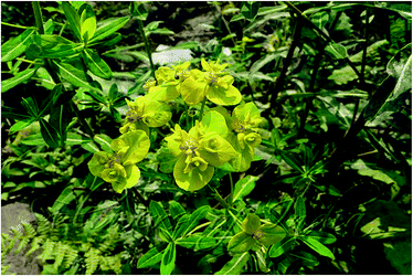
The genus of Euphorbia belongs to the family Euphorbiaceae (spurge family) with many species; most of them are found in China, Western and Central Himalaya, Mediterranean, Middle East, South Africa and southern USA. Most are herbs but some are shrubs or trees. Plants of the genus Euphorbia are perennial herbaceous plants containing latex and have unique flower structures.9,10 Members of Euphorbia are rich in phenolics, aromatic esters, steroids, diterpenoids, tetracyclic triterpenoids, pentacyclic triterpenoids, essential oils and several bioactive constituents.11 A chemical literature survey of Euphorbia wallichii revealed the presence of various range of phytochemicals especially antioxidant phenolics aglycones and glycosides such as flavonoid aglycones, quercetin, kaempferol and myricetin and those with sugar moieties demonstrated in different parts of the plant along with their application as antimicrobial, antioxidant, anticancer, anti proliferation, anti fungi.12 These phyto-constituents confirmed the application of Euphorbia wallichii leaf (Fig. 1) extract as a suitable source for synthesis of nanoparticles using the reducing ability of these potent antioxidants.
To benefit the valuable applications of metal NPs and in continuation of our recent works on the green chemistry via heterogeneous catalysis,13 herein, we prepare Cu/RGO/Fe3O4 nanocomposite via new, green, simple, cost effective and environment friendly process by Euphorbia wallichii leaf extract as a reducing and stabilizing agent. The synthesized nanocomposite was used as a new magnetically recoverable catalyst for the reduction of 4-NP and RhB in water at room temperature. However, there is no report on the biosynthesis of Cu/RGO/Fe3O4 magnetic nanocomposite by utilizing the leaf extract of Euphorbia wallichii and its application for the reduction of colorless organic pollutants at room temperature.
Results and discussion
In this study, a valuable approach in synthesis of Cu/RGO/Fe3O4 magnetic nanocomposite using Euphorbia wallichii leaf extract is demonstrated. Of course it should be mentioned that these types of researches suffer from some aspects. For example production of nanoparticles using plants in large scale is challengeable because a large amount of the plants eventually special species are required which can cause to extinct or endanger of corresponding species. From this view it is not an environmental friendly. Also there are several environmental conditions such as life time, light conditions, soil conditions, temperature, humidity and height of the place influenced on the amount and type of phytochemicals inside the plants in which even the same plants from two different regions should be strongly considered while doing the research. Furthermore, during these types of studies the biosynthesized nanoparticles used as nanocatalysts for run an organic reaction, are from a green source but the application of synthesized NPs is in a non-green environment of organic solvents.For more accuracy, we first synthesized each part individually and studied them in terms of properties and identifications then we synthesized the Cu/RGO/Fe3O4 magnetic nanocomposite (see Experimental section). Therefore, for further monitoring, first Cu NPs were individually synthesized using Euphorbia wallichii leaf extract as a reducing and stabilizing agent. The obtained NPs were monitored using UV-vis and FT-IR and XRD.
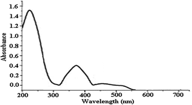
The UV-vis spectrum of the plant extract shows bonds at λmax 365 (bond 1) due to the cinnamoyl system of conjugated aromatics; and 240 (bond II) for the absorbance of benzoyl system in conjugated aromatic systems (Fig. 2). Therefore, this spectrum strongly supports the presence of phenolics as indicated in literatures.14
The UV-vis spectrum of green synthesized Cu NPs using Euphorbia wallichii leaf extract (Fig. 3) showed the significant changes in the absorbance maxima due to surface plasmon resonance demonstrating the formation of Cu NPs. The color of the solution immediately changed into dark indicated the formation of Cu NPs as characterized by UV-vis spectrum. The synthesized copper NPs by this method are quite stable with no significant variance in the shape, position and symmetry of the absorption peak even after 20 days with λmax ranging 550 to 580 nm at interval times. Of course the wavelength corresponding to the extinction maximum of the SPR is highly dependent on the size, shape, and dielectric properties of the metal nanoparticles. The primary consequences of SPR excitation are selective photon absorption, scattering and local electromagnetic field enhancement. The influence of time on λmax strongly depends on the structural changes of phytochemicals adsorbed on the nano surface which causes some variations in extinction maximum of the SPR and λmax.14
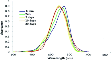 | ||
| Fig. 3 UV-vis spectrum of green synthesized Cu NPs using the aqueous extract of leaves of Euphorbia wallichii between 5 min to 20 days. | ||
The FT-IR analysis was carried out to identify the possible biomolecules responsible for the reduction of Cu(II) ions and capping the bioreduced nanoparticles. The FT-IR spectrum of the crude extract (Fig. 4A) depicted some peaks at 3500 to 3100, 1725 and 1415 cm−1 which represent the OH functional group in molecule and OH involving hydrogen bonds, carbonyl group (C![[double bond, length as m-dash]](https://www.rsc.org/images/entities/char_e001.gif) O) and stretching C
O) and stretching C![[double bond, length as m-dash]](https://www.rsc.org/images/entities/char_e001.gif) C aromatic ring vibrations, respectively. Furthermore, the FT-IR of Cu NPs shows demonstrative differences in the shape and location of signals indicating the interaction between CuCl2·2H2O and involved sites of phytochemicals (Fig. 4B). Changing the location of the peaks at 3500 to 3100, 1695, 1442, 1300 and 1000 cm−1 represent the OH functional group, carbonyl group (C
C aromatic ring vibrations, respectively. Furthermore, the FT-IR of Cu NPs shows demonstrative differences in the shape and location of signals indicating the interaction between CuCl2·2H2O and involved sites of phytochemicals (Fig. 4B). Changing the location of the peaks at 3500 to 3100, 1695, 1442, 1300 and 1000 cm−1 represent the OH functional group, carbonyl group (C![[double bond, length as m-dash]](https://www.rsc.org/images/entities/char_e001.gif) O), stretching C
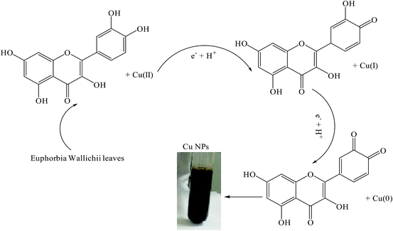
O), stretching C![[double bond, length as m-dash]](https://www.rsc.org/images/entities/char_e001.gif) C aromatic ring and C–OH stretching vibrations, respectively. Polyphenolics could be adsorbed on the surface of metal nanoparticles, possibly by interaction through π–electrons interaction in the absence of other strong ligating agents (Scheme 1). Polyphenolics and other chemicals within Euphorbia wallichii leaf extract are not only cogently reduce the copper salts but also provide excellent tenacity against agglomeration. These are in agreement with our previous findings.8e,8f
C aromatic ring and C–OH stretching vibrations, respectively. Polyphenolics could be adsorbed on the surface of metal nanoparticles, possibly by interaction through π–electrons interaction in the absence of other strong ligating agents (Scheme 1). Polyphenolics and other chemicals within Euphorbia wallichii leaf extract are not only cogently reduce the copper salts but also provide excellent tenacity against agglomeration. These are in agreement with our previous findings.8e,8f
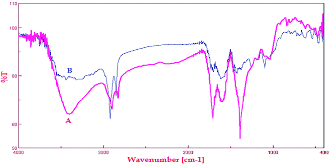 | ||
| Fig. 4 FT-IR spectra of (A) Euphorbia wallichii leaf extract and (B) FT-IR spectrum of green synthesized Cu NPs. | ||
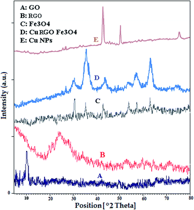
Cu NPs were also characterized by X-ray diffraction (XRD). The patterns at 2θ values 43.5°, 50.08° and 74.6° (Fig. 5E) can be assigned to (111), (200) and (220) crystal planes in Cu cubic structure which agrees with the standard Cu (JCPDS 71-4610).15 There are not any other diffraction peaks arising from CuO, Cu2O, Cu(OH)2 in the XRD pattern, which indicate the high phase purity of synthesized sample.
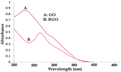
In the next step, RGO was prepared from GO using Euphorbia wallichii leaf extract. Formation of RGO was initially monitored using UV-visible spectroscopy. Fig. 6A shows the absorption spectrum of synthesized RGO and GO. An absorption peak was observed at λmax 230 nm due to the π → π* transition of aromatic C–C, which is a characteristic band for the GO. Also, the shoulder peak was observed at 297 nm due to the n → π* transition of C![[double bond, length as m-dash]](https://www.rsc.org/images/entities/char_e001.gif) O bonds. Changes in the conversion of GO to RGO were monitored by the UV-vis absorption spectrum (Fig. 6B). The peak at 265 nm confirmed the formation of RGO using Euphorbia wallichii leaf extract. In addition, the characteristic C
O bonds. Changes in the conversion of GO to RGO were monitored by the UV-vis absorption spectrum (Fig. 6B). The peak at 265 nm confirmed the formation of RGO using Euphorbia wallichii leaf extract. In addition, the characteristic C![[double bond, length as m-dash]](https://www.rsc.org/images/entities/char_e001.gif) O bond at 297 nm that was completely disappeared, specifying the complete reduction of GO to RGO.
O bond at 297 nm that was completely disappeared, specifying the complete reduction of GO to RGO.
The XRD analysis of GO (Fig. 5A) shows diffraction peak at 2θ of 10.2° (001). The synthesized RGO from GO using extract of the leaf of Euphorbia wallichii exhibited a broad diffraction peak at 2θ of 24.2° (002 crystal plane), Fig. 5B.16
Then, Fe3O4 NPs was prepared from FeCl3·6H2O through biological reduction of Fe3+ ion using Euphorbia wallichii leaf extract. After completion of the reduction, the separated Fe3O4 NPs were dried and subjected to X-ray diffraction analysis.
XRD analysis of Fe3O4 NPs (Fig. 5C) shows major diffraction peaks at 30.8°, 35.7°, 43.1°, 54.2°, 57.0° and 63.1° (2θ), which can be assigned to (220), (311), (400), (422), (511), and (440) planes of the cubic Fe3O4 (JCPDS 19-0629).
Finally the Euphorbia wallichii leaf extract was used for the synthesis of the Cu/RGO/Fe3O4 magnetic nanocomposite by treating with GO, FeCl3·6H2O and CuCl2·2H2O as raw materials through a one step method.
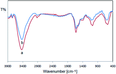
FT-IR analysis is performed to know the components responsible for the capping on the produced Cu/RGO/Fe3O4 nanocomposite. The FT-IR spectrum of Cu/RGO/Fe3O4 nanocomposite is shown in Fig. 7a. The bands around 565 cm−1 was assigned to the stretching mode of Fe–O. Changing the location of peaks at 3437, 1602 and 1081 cm−1 represents the OH functional groups, stretching C![[double bond, length as m-dash]](https://www.rsc.org/images/entities/char_e001.gif) C aromatic ring and C–O stretching vibrations, respectively. The peak positioned around 1627 cm−1 in the FT-IR spectrum demonstrated the bending vibration of O–H. All these results confirmed the decoration of Euphorbia wallichii molecules on the surface of Cu/RGO/Fe3O4 nanocomposite which are responsible for its stabilization. In fact the phytochemicals adsorbed on the surface of catalyst form a layer on nanocomposite which prevents agglomeration and oxidizing processes on the surface of catalyst and also stabilize the catalyst during reaction cycles. Therefore, this phenomenon improves the catalytic activity without significant loss of its efficiency.
C aromatic ring and C–O stretching vibrations, respectively. The peak positioned around 1627 cm−1 in the FT-IR spectrum demonstrated the bending vibration of O–H. All these results confirmed the decoration of Euphorbia wallichii molecules on the surface of Cu/RGO/Fe3O4 nanocomposite which are responsible for its stabilization. In fact the phytochemicals adsorbed on the surface of catalyst form a layer on nanocomposite which prevents agglomeration and oxidizing processes on the surface of catalyst and also stabilize the catalyst during reaction cycles. Therefore, this phenomenon improves the catalytic activity without significant loss of its efficiency.
XRD analysis of Cu/RGO/Fe3O4 nanocomposite (Fig. 5D) shows major diffraction peaks at 30.05°, 35.5°, 43.4°, 54.4°, 57.5° and 63.5° (2θ), which can be indexed to (220), (311), (400), (422), (511) and (440) planes of the cubic Fe3O4 (JCPDS 19-0629). Of course there is a weak signal around ca. 50 for Cu but most likely in the XRD pattern of composite, it is overlapped by the other peaks which effected the strength of the peak. Also, the peak positions at 2θ values 43.4°, 50.07° and 74.7° in pattern are corresponded to (111), (200) and (220) cubic structure of Cu.
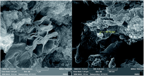
Fig. 8 represents the results of field emission scanning electron micrograms (FESEM) in order to investigate the particle size and morphology of the Cu/RGO/Fe3O4 nanocomposite. As Fig. 8 shows, the surface of RGO is densely covered by narrowly distributed Fe3O4 and Cu NPs. This result indicates the perfect combination of Fe3O4, Cu NPs and RGO sheets.
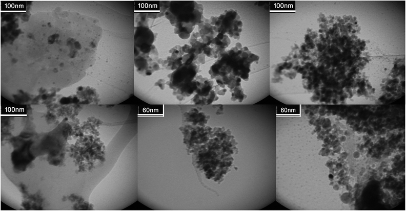
Fig. 9 shows the TEM images of the Cu/RGO/Fe3O4 nanocomposite at different magnifications. Fe3O4 and Cu NPs are uniformly dispersed on the surface of RGO with a narrow size distribution. The average particle size of the Fe3O4 and Cu NPs are about 10–15 nm, which is consistent with the SEM observation. These particles are generally spherical in shape. Some nanoparticles aggregation is observed. However, it is difficult to differentiate Fe3O4 and Cu NPs from each other due to their similar appearance. The distributions of the elements in the Cu/RGO/Fe3O4 nanocomposite were also observed vividly by EDS spectrum and the EDS elemental mapping. The distribution of the Fe3O4 and Cu NPs was expected to offer an enhanced catalytic activity.
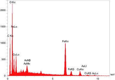
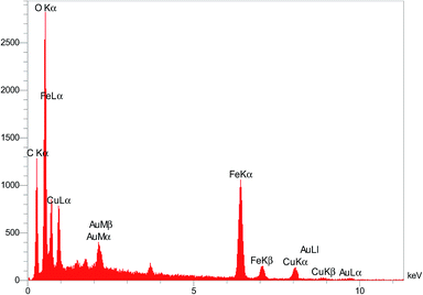
In order to further confirm of the surface composition of Cu/RGO/Fe3O4 nanocomposite, we take the elemental mapping by energy dispersive X-ray absorption spectroscopy (EDS). The EDS spectrum in Fig. 10 shows the presence of C, Fe, O and Cu elements in the Cu/RGO/Fe3O4 nanocomposite. Further, the presence of copper and iron was approved using the elemental mapping images (Fig. 11). Concerning the results of XRD and SEM for the Cu/RGO/Fe3O4 nanocomposite, we can confirm that Cu and Fe3O4 nanocrystallites were exactly fabricated.
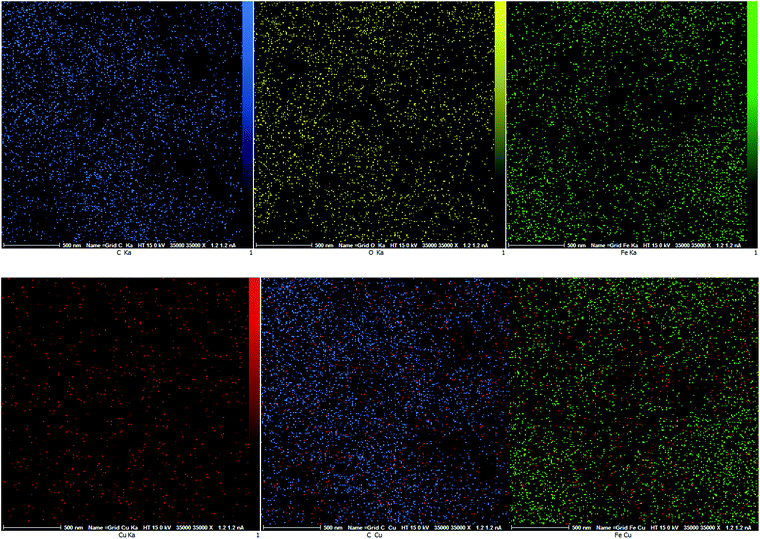 | ||
| Fig. 11 EDS elemental mapping of the Cu/RGO/Fe3O4 nanocomposite, O (yellow), C (blue), Fe (green) and Cu (red). | ||
The surface area and pore size distributions of the Cu/RGO/Fe3O4 magnetic nanocomposite can be obtained by the N2 adsorption–desorption isotherms. The measured Brunauer–Emmett–Teller (BET) surface area of the Cu/RGO/Fe3O4 magnetic nanocomposite was 27.69 m2 g−1. Moreover, the Barrett–Joyner–Halenda (BJH) analysis showed that the average pore diameter is 16.1 nm and the pore volume is 0.1113 cm3 g−1.
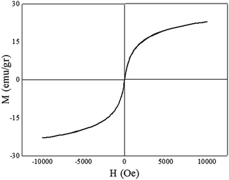
The magnetic hysteresis measurement of the Cu/RGO/Fe3O4 magnetic nanocomposite obtained by VSM system at room temperature with the field sweeping from −10![[thin space (1/6-em)]](https://www.rsc.org/images/entities/char_2009.gif) 000 to +10
000 to +10![[thin space (1/6-em)]](https://www.rsc.org/images/entities/char_2009.gif) 000 Oe. Fig. 12 showed that the Cu/RGO/Fe3O4 magnetic nanocomposite had a magnetization saturation value of 23.13 emu g−1 and demonstrated its magnetic behavior. These results indicated that the catalyst can be easily separated by the application of external magnetic field after the reaction completed.
000 Oe. Fig. 12 showed that the Cu/RGO/Fe3O4 magnetic nanocomposite had a magnetization saturation value of 23.13 emu g−1 and demonstrated its magnetic behavior. These results indicated that the catalyst can be easily separated by the application of external magnetic field after the reaction completed.
Catalytic performance of the Cu/RGO/Fe3O4 nanocomposite in 4-NP and RhB reduction
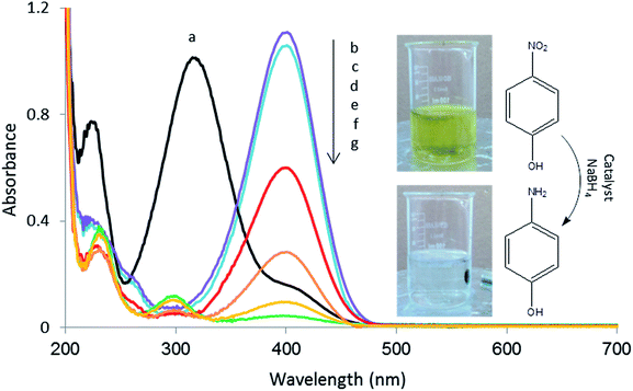
The catalytic activity of the Cu/RGO/Fe3O4 nanocomposite was tested by the reduction of 4-NP to 4-aminophenol (4-AP) in the presence of NaBH4 at room temperature.The conversion of 4-NP to 4-AP in aqueous medium was monitored using UV-visible measurements at room temperature. The absorption peak at 317 nm is assigned to pure 4-NP solution, which shifts to 400 nm after adding an aqueous solution of NaBH4 (Fig. 13). This was due to the formation of 4-nitrophenolate ion under alkaline conditions using addition of NaBH4.17 The yellow solution of mixed 4-NP and NaBH4 became colourless after the complete reduction. As the reaction time increased, the peak at 400 nm decreased while a new peak simultaneously appeared at 300 nm corresponding to 4-AP. The absorption peak at 400 nm is fully disappeared in the presence of 5.0 mg of catalyst after 3![[thin space (1/6-em)]](https://www.rsc.org/images/entities/char_2009.gif) :
:![[thin space (1/6-em)]](https://www.rsc.org/images/entities/char_2009.gif) 15 min induction period.
15 min induction period.
The concentration ratio of NaBH4 to 4-NP was kept high during the reaction to ensure that the reaction followed pseudo-first order kinetics.18 The kinetic equation for the reduction can be written as follows.19
| ln(Ct/C0) = ln(At/A0) = −kt |
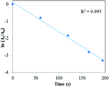 | ||
| Fig. 14 Plot of ln(At/A0) vs. irradiation time for 4-NP reduction, conditions: [4-NP] = 2.5 × 10⁻³ M; [NaBH4] = 0.25 M; catalyst = 5.0 mg. | ||
| Catalyst | Concentration of 4-NP (mM) [mmol] | Concentration of NaBH4 (mM) [mmol] | Time (min) | k (min−1) | Ref. |
|---|---|---|---|---|---|
| NiFe2O4 NPs | 36 [0.72] | 1798 [36] | 16 | 0.12 | 20a |
| Ni NPs | 0.1 [3 × 10⁻⁴] | 200 [0.06] | 16 | 0.16 | 20b |
| Ni/graphene nanocomposite | 0.1 [2 × 10⁻³] | 132 [0.26] | 4 | 0.7 | 20c |
| Cu–Fe3O4@graphene composite | 1 [0.01] | 92.5 [1.85] | 5 | 0.7 | 20d |
| Pd–graphene nanohybrid | 0.1 [2.9 × 10⁻⁴] | 10 [1 × 10⁻³] | 12 | 0.14 | 20e |
| Cu3Ni2 bimetallic nanocrystals | 0.1 [2 × 10⁻³] | 20 [0.1] | 6 | 0.58 | 20f |
| NiCo2 alloy microstructure | 0.1 [1 × 10⁻³] | 60 [0.6] | 30 | 0.07 | 20g |
| FeNi2 alloy nanostructure | 0.1 [1 × 10⁻⁴] | 60 [0.06] | 60 | 0.06 | 20h |
| Au NPs/ionic liquid–graphene | 0.025 [3.7 × 10⁻⁵] | 2.5 [3.8 × 10⁻³] | 7 | 0.40 | 20i |
| Au–Pd bimetallic NPs/graphene | 0.1 [1 × 10⁻⁵] | 10 [0.01] | 3![[thin space (1/6-em)]](https://www.rsc.org/images/entities/char_2009.gif) : :![[thin space (1/6-em)]](https://www.rsc.org/images/entities/char_2009.gif) 5 5 |
0.87 | 20j |
| Cu/RGO/Fe3O4 nanocomposite | 2.5 [0.05] | 250 [6.25] | 3![[thin space (1/6-em)]](https://www.rsc.org/images/entities/char_2009.gif) : :![[thin space (1/6-em)]](https://www.rsc.org/images/entities/char_2009.gif) 15 15 |
1.02 | This work |
The Cu/RGO/Fe3O4 nanocomposite showed better catalytic activity than Cu NPs which indicates that the catalytic activity of Cu NPs can be remarkably improved by combining it using RGO/Fe3O4. According the results, reaction took place after 580 s in the presence of Cu NPs.15 But when the Cu/RGO/Fe3O4 nanocomposite was used as the catalyst, the reduction process proceeded much faster and completed during 195 s. RGO/Fe3O4 is not only a support to prevent aggregation of Cu NPs, but also can provide a synergistic effect, which allow more molecules to be in contact with the surface of Cu NPs. The Cu/RGO/Fe3O4 nanocomposite has a higher surface area which can provide more active sites for adsorption of reactants via π–π stacking interactions. Such adsorption provides a relatively high concentration of reactant molecules which are closer to the Cu NPs on RGO/Fe3O4, leading to highly efficient contact between them. The conversion of 4-NP to 4-AP using Cu/RGO/Fe3O4 magnetic nanocomposite is an electron transfer process. When Cu/RGO/Fe3O4 magnetic nanocomposite is used for catalytic reduction of 4-NP, the Cu NPs can transfer electrons from BH4− to 4-NP, which are both adsorbed on the catalyst, leading to the production of 4-AP. BH4− as a nucleophile can donate electrons to the Cu NPs and 4-NP as an electrophile can capture electrons from the Cu NPs. After electron transfer (ET) to the Cu NPs, the hydrogen atom forms from the hydride, and then attacks 4-nitrophenolate ions to reduce it. This ET-induced hydrogenation of 4-NP occurred spontaneously at the surface of the metal catalyst. Finally, the generated product was desorbed from the surface of the catalyst. These are in agreement with previous reported findings in the literature works.21 In all cases, the metal catalysts play an important role as electron relays for the reduction of 4-NP with NaBH4.21
We also perform a comparative study of the activity of Cu/RGO/Fe3O4 magnetic nanocomposite with other reported catalysts for the reduction of 4-NP to 4-AP with NaBH4 (Table 1). With an overall look at Table 1, we can say that our method is comparable with other reported methods in term of reaction time.
Compared with the other literatures on the reduction of 4-NP to 4-AP,20 the notable features of our method are: (i) elimination of toxic reagents for the preparation of catalyst; (ii) the time of the reaction is short; (iii) the conversion of 4-NP to 4-AP is very high; (iv) the pseudo-first order rate constant of the reaction is high; (v) ease of handling and cost efficiency of the catalyst; (vi) the use of Euphorbia wallichii leaf extract as an economic and effective alternative represents an interesting, fast and clean synthetic route for the preparation of Cu/RGO/Fe3O4 magnetic nanocomposite; (vii) no surfactant, capping agent, and/or template were used for the preparation of Cu/RGO/Fe3O4 magnetic nanocomposite and (viii) the Cu/RGO/Fe3O4 magnetic nanocomposite can be easily recovered and reused.
Of course we emphasized on the green synthesis of nanoparticles and catalyst, for the following proofs: (i) our source was plant as a green source; (ii) the mechanism of synthesized NPs is according the bioactivity of natural source; (iii) phytochemicals responsible for this synthesis were taken from a green source; (iv) certainly the purchased quercetin shows the ability for this green synthesis but in our work we believe this is not only a special phytochemical responsible for this green synthesis but also a spectrum of antioxidants in the plant extracts do this job.
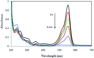
Catalytic degradation of RhB dye using the Cu/RGO/Fe3O4 nanocomposite via electron transfer of BH4− ions was monitored by recording the time-dependent UV-vis absorption spectra of the mixture using spectrophotometer. Fig. 15 shows the successive UV-visible absorption spectra of the RhB reduction solution in the presence of 10.0 mg of the Cu/RGO/Fe3O4 nanocomposite. RhB dye exhibited one characteristic SPR band at 554 nm. As shown in Fig. 15, when the reduction of RhB is initiated, the spectral band of RhB at 554 nm decreased with reaction time, indicating the Cu/RGO/Fe3O4 nanocomposite was able to reduce RhB at room temperature. It was observed that decolorization of RhB occurred within 5 min. Due to the presence of large excess of NaBH4 compared to RhB, the rate of reaction is independent on the concentration of NaBH4, and similar to the reduction of 4-NP, the decolorization of RhB can be treated as a pseudo-first reaction.
The catalytic activity of the Cu/RGO/Fe3O4 nanocomposite was compared with other reported catalysts in reduction of RhB (Table 2). It is evident from Table 2 that the Cu/RGO/Fe3O4 nanocomposite made in our work can finish the reduction reaction in the shortest time with the least mass of the catalyst for converting the same amount of RhB. We believe that due to the presence of Cu NPs on the RGO/Fe3O4 surface, the electron transfer rate becomes much faster which in turn increases the catalysis reaction rates. It is important to note that Euphorbia wallichii leaf extract played the dual role of reducing and stabilizing agent for the formation of Cu NPs without the need for addition of any external reducing agents such as hydrazine, sodium borohydride, sugar etc.
Recovery and reuse of the Cu/RGO/Fe3O4 nanocomposite
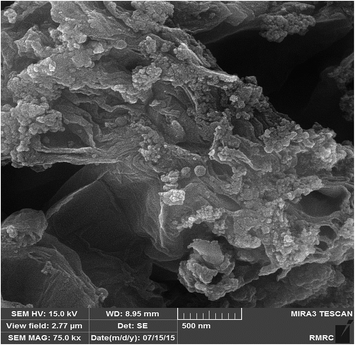
One of the main advantages of using a magnetic catalyst in a reaction is the ease of separation and reuse in several cycles, especially for commercial and industrial applications. The reusability and activity of the catalyst was checked in the decolorization of dyes with NaBH4. After completion of the reaction in the first run, the nanocomposite was separated from the reaction mixture by an external magnetic field and the resulting solid mass was washed with water and dried then reused for the next run. The catalytic activity did not decrease considerably even after six catalytic cycles (Table 3). The FESEM image and EDX spectrum of the Cu/RGO/Fe3O4 nanocomposite after being reused for six times showed no chemical and morphological alterations (Fig. 16 and 17). Furthermore, the stability of the catalyst was studied by Inductively Coupled Plasma Atomic Emission Spectroscopy (ICP-AES) analysis of the resulting reaction solution mixture after six times reuse which the results showed only a very small amount (less than 1%) of Cu metal removed from the magnetic catalyst. Comparison of the FT-IR spectra of recycled catalyst (Fig. 7b) with fresh catalyst demonstrates that the structure of the Cu/RGO/Fe3O4 nanocomposite retained after the first and sixth recoveries.| Entry | Time (sec) | Recovery of catalyst (%) |
|---|---|---|
| a Reaction conditions: [4-NP] = 2.5 × 10⁻³ M, [NaBH4] = 0.25 M, catalyst = 5.0 mg. | ||
| Refresh | 195 | 99 |
| 1 | 195 | 99 |
| 2 | 195 | 99 |
| 3 | 195 | 98 |
| 4 | 200 | 98 |
| 5 | 200 | 97 |
| 6 | 205 | 96 |
Conclusion
In summary, we have demonstrated that the aqueous extract containing phenolics derived from the naturally available Euphorbia wallichii leaf acts as a good reducing and stabilizing agent in synthesis procedure of Cu/RGO/Fe3O4 nanocomposite. This reported synthetic method is simple, inexpensive, easily scaled up and environmentally benign because it does not require an extra surfactant or reductant, organic solvent and hazardous materials. Moreover, the synthesized catalyst exhibited excellent activity for the reduction of 4-NP and RhB in water at room temperature. The Cu/RGO/Fe3O4 nanocomposite was found to be highly active and could be recycled by means of an external magnet for several consecutive runs without significant loss of catalytic activity. Further investigation on the Cu/RGO/Fe3O4 nanocomposite catalytic activity in organic transformations is underway in our laboratory.Experimental
High-purity chemical reagents were purchased from the Merck and Aldrich chemical companies. All materials were of commercial reagent grade. FT-IR spectra were recorded on a Nicolet 370 FT/IR spectrometer (Thermo Nicolet, USA) using pressed KBr pellets which the sample of NPs for analysis using FT-IR was converted to the pellet using KBr under pressure and the FT-IR spectrum of the extract was obtained using a drop of liquid sample of the extract on KBr plates. X-ray diffraction (XRD) measurements were carried out using a Philips powder diffractometer type PW 1373 goniometer (Cu Kα = 1.5406 Å). The scanning rate was 2° min−1 in the 2θ range from 10 to 80°. UV-visible spectral analysis was recorded on a double-beam spectrophotometer (Hitachi, U-2900) to ensure the formation of nanoparticles. The shape and size of nanocomposite was identified by transmission electron microscope (TEM) using a Philips EM208 microscope operating at an accelerating voltage of 90 kV. Morphology and particle dispersion was investigated by scanning electron microscopy (SEM) (Cam scan MV2300). The chemical composition of the prepared nanostructures was measured by EDS (Energy Dispersive X-ray Spectroscopy) performed in SEM. The Brunauer–Emmett–Teller (BET) specific surface areas (SBET) and the porosity of the samples were evaluated on the basis of nitrogen adsorption isotherms measured at 77 K using a BELSORP-max nitrogen adsorption apparatus (Japan Inc.). VSM (Vibrating sample magnetometer) measurements were performed by using a SQUID magnetometer at 298 K (Quantum Design MPMS XL).Preparation of Euphorbia wallichii leaf extract
50 g of dried leaf powdered of Euphorbia wallichii was added to 250 mL double distillated water in 500 mL flask and well mixed. The preparation of extract was using magnetic heating stirrer at 70 °C for 30 min. The obtained extract was centrifuged in 7000 rpm and filtered then filtrate was kept under inert atmosphere of argon for more protection and precession of our research.Preparation of Cu NPs using Euphorbia wallichii leaf extract
In a 250 mL conical flask, 10 mL solution of CuCl2·2H2O 7 mM was mixed with 100 mL of the aqueous plant extract along with vigorous shaking until gradually changing the color of the mixture to dark during 5 min indicating the formation of Cu nanoparticles (as monitored by UV-vis and FT-IR spectra of the solution). The well shaked mixture then filtered and centrifuged at 7000 rpm for 30 min and obtained precipitation washed with n-hexane and absolute ethanol to remove possible impurities. Then it was kept under inert atmosphere of argon for more protection and precession of our research.Preparation of the GO
The GO was prepared from natural graphite powder by a modified Hummers method.23Preparation of the RGO using Euphorbia wallichii leaf extract
For the preparation of RGO, 80 mg of GO was dispersed in 50 mL distilled water in a beaker by sonication for a period of 30 min. The suspension was thoroughly mixed with an appropriate volume of Euphorbia wallichii leaf extract and magnetically stirred under reflux conditions for 6 h. The obtained product was centrifuged at 12![[thin space (1/6-em)]](https://www.rsc.org/images/entities/char_2009.gif) 000 rpm and dried at 100 °C. Then it was kept under inert atmosphere of argon for more protection and precession of our research.
000 rpm and dried at 100 °C. Then it was kept under inert atmosphere of argon for more protection and precession of our research.
Preparation of the Fe3O4 NPs using Euphorbia wallichii leaf extract
In a 250 mL conical flask, 0.1 M FeCl3·6H2O was gradually added to the prepared extract with the 1![[thin space (1/6-em)]](https://www.rsc.org/images/entities/char_2009.gif) :
:![[thin space (1/6-em)]](https://www.rsc.org/images/entities/char_2009.gif) 1 volume ratio and magnetically stirred at room temperature for 30 min. The progress of the reaction was monitored by UV-visible spectroscopy. After completion of the reduction, Fe3O4 NPs were separated out by centrifugation at 12
1 volume ratio and magnetically stirred at room temperature for 30 min. The progress of the reaction was monitored by UV-visible spectroscopy. After completion of the reduction, Fe3O4 NPs were separated out by centrifugation at 12![[thin space (1/6-em)]](https://www.rsc.org/images/entities/char_2009.gif) 000 rpm. Then it was kept under inert atmosphere of argon for more protection and precession of our research.
000 rpm. Then it was kept under inert atmosphere of argon for more protection and precession of our research.
Green synthesis of Cu/RGO/Fe3O4 nanocomposite using Euphorbia wallichii leaf extract
0.1 M FeCl3·6H2O and 0.07 M CuCl2·2H2O were gradually added into the stable GO dispersion (1 mg mL−1) and magnetically stirred for 1 h. Then, the above extract was added into mixture under vigorous stirring and refluxed for 6 h. The obtained product was collected using an external magnetic field, washed several times with deionized water and absolute ethanol and dried in vacuum oven at 100 °C for 2 h. Then it was kept under inert atmosphere of argon for more protection and precession of our research.Catalytic reduction of 4-NP
Typically, 25 mL of 4-NP solution (2.5 mM) and 5.0 mg of the Cu/RGO/Fe3O4 nanocomposite were mixed in a beaker. After keeping the mixture at room temperature for 2 min, 25 mL of the newly prepared NaBH4 (0.25 M) was added to start the reaction. The solution turned from light yellow to bright yellow immediately after the aqueous NaBH4 was added. The mixture was allowed to stir until the deep yellow solution became colorless. Changes in the concentration of 4-NP were monitored by the UV-vis absorption spectra, which were recorded in the scanning range of 200–700 nm at room temperature. 1 mL of the solution was extracted and diluted to 25 mL for further UV-vis absorption analysis at certain intervals. For the recycling experiment, the catalyst was collected using an external magnetic field, washed with ethanol, dried and then reused.Catalytic reduction of RhB
Typically, 10.0 mg of catalyst was added to 25 mL of RhB aqueous solution (2.09 × 10⁻⁵). Next, 25 mL of freshly prepared aqueous NaBH4 (5.3 × 10⁻³) was added and the mixture was allowed to stir at room temperature. The progress of the conversion reaction was then monitored by recording the time-dependent UV-vis absorption spectra of the mixture using a spectrophotometer. At the end of the reaction, the catalyst was simply separated from the reaction system by an external magnetic field and the resulting solid mass was washed with ethanol and dried and reused for the next cycle.Acknowledgements
We gratefully acknowledge the Iranian Nano Council and the University of Qom for the support of this work.References
- (a) I. M. Banat, P. Nigam, D. Singh and R. Marchant, Bioresour. Technol., 1996, 58, 217 CrossRef CAS; (b) C. A. Martinez-Huitle and E. Brillas, Appl. Catal., B, 2009, 87, 105 CrossRef CAS PubMed; (c) V. K. Vidhu and D. Philip, Micron, 2014, 56, 54 CrossRef CAS PubMed.
- (a) B. Manu and S. Chaudhari, Bioresour. Technol., 2002, 82, 225 CrossRef CAS; (b) R. Patel and S. Suresh, J. Hazard. Mater., 2006, 137, 1729 CrossRef CAS PubMed; (c) L. G. Devi, S. G. Kumar, K. M. Reddy and C. Munikrishnappa, J. Hazard. Mater., 2009, 164, 459 CrossRef PubMed.
- (a) N. Pradhan, A. Pal and T. Pal, Langmuir, 2001, 17, 1800 CrossRef CAS; (b) A. K. Sinha, M. Basu, S. Sarkar, M. Pradhan and T. Pal, J. Colloid Interface Sci., 2013, 398, 13 CrossRef CAS PubMed; (c) N. Gupta, H. M. Singh and R. K. Sharma, J. Mol. Catal. A: Chem., 2011, 335, 248 CrossRef CAS PubMed; (d) S. M. El-Sheikh, A. A. Ismail and J. F. Al-Sharab, New J. Chem., 2013, 37, 2399 RSC; (e) X. Zhang, M. Lin, X. Lin, C. Zhang, H. Wei, H. Zhang and B. Yang, ACS Appl. Mater. Interfaces, 2014, 6, 450 CrossRef CAS PubMed.
- (a) L. Jiang, Y. Wang, X. Liu, Y. Cao and K. Wei, Chin. J. Catal., 2013, 34(12), 2271 CrossRef CAS; (b) J. D. Robert, J. Catal., 2003, 216(1), 396 Search PubMed; (c) S. Jing, L. Luo, S. Yin, F. Huang, Y. Jia, Y. Wei, Z. Sun and Y. Zhao, Appl. Catal., B, 2014, 147, 897 CrossRef CAS PubMed; (d) L. H. Yu, C. H. Kuo and Y. Chuin-Tih, J. Am. Chem. Soc., 2007, 129(32), 9999 CrossRef PubMed; (e) H. Hans, H. Ratna, C. Dai, B. R. Carolus, G. Buana and J. H. Hero, Green Chem., 2009, 11, 1247 RSC; (f) R. R. Debra, Science, 2003, 299(5613), 1698 CrossRef PubMed; (g) V. Polshettiwar, B. Baruwati and R. S. Varma, Green Chem., 2009, 11, 127 RSC; (h) R. Poisson, J.-P. Brunelle and P. Nortier, Catalyst Supports and Supported Catalysts, ed. A. B. Stiles, Butterworth, Boston, 1987, p. 11 Search PubMed; (i) M. Nasrollahzadeh, B. Jaleh, P. Fakhri, A. Zahraei and E. Ghadery, RSC Adv., 2015, 5, 2785 RSC; (j) M. Nasrollahzadeh, S. M. Sajadi, A. Rostami-Vartooni and M. Bagherzadeh, J. Colloid Interface Sci., 2015, 448, 106 CrossRef CAS PubMed; (k) Z. Yingke, N. Kenneth, S. O. Tim, P. Svitlana, B. Justin, N. D. Huyen, G. Thomas, S. Zongping and O. Ryan, Energy Environ. Sci., 2010, 3, 1437 RSC; (l) M. Nasrollahzadeh, S. M. Sajadi, A. Rostami-Vartooni, M. Bagherzadeh and R. Safari, J. Mol. Catal. A: Chem., 2014, 400, 22 CrossRef PubMed; (m) M. Nasrollahzadeh, S. M. Sajadi, A. Rostami-Vartooni and M. Khalaj, J. Mol. Catal. A: Chem., 2015, 396, 31 CrossRef CAS PubMed.
- (a) N. Muhd Julkapli and S. Bagheri, Int. J. Hydrogen Energy, 2015, 40, 948 CrossRef PubMed; (b) L. Yanguang, W. Hailiang, X. Liming, L. Yongye, H. Guosong and D. Hongjie, J. Am. Chem. Soc., 2011, 133(19), 7296 CrossRef PubMed; (c) D. R. Dreyer, S. Park, C. W. Bielawski and R. S. Ruoff, Chem. Soc. Rev., 2010, 39, 228 RSC; (d) G. Shaojun, D. Shaojun and W. Erkang, ACS Nano, 2010, 4(1), 547 CrossRef PubMed; (e) F. Chekin, S. Bagheri and S. B. A. Hamid, J. Solid State Electrochem., 2014, 18, 893 CrossRef CAS; (f) P. Fakhri, M. Nasrollahzadeh and B. Jaleh, RSC Adv., 2014, 4, 48691 RSC; (g) D. Lifeng, R. S. G. Raghavendar, L. Zhou, M. C. Michael and H. Shifeng, Carbon, 2010, 48(3), 781 CrossRef PubMed; (h) T. Farnosh and S.-N. Masoud, J. Ind. Eng. Chem., 2014, 20(5), 3170 CrossRef PubMed; (i) Q. J. Wang and J. G. Che, Phys. Rev. Lett., 2009, 103, 066802 CrossRef CAS; (j) M. S. Gil, R. Luigi, S. Peter, B. Willi and M. Rolf, J. Am. Chem. Soc., 2009, 131(23), 8262 CrossRef PubMed.
- (a) Y. Gao, D. Ma, G. Hu, P. Zhai, X. Bao, B. Zhu, B. Zhang and D. S. Su, Angew. Chem., Int. Ed., 2011, 50, 10236 CrossRef CAS PubMed; (b) D. Yu and L. Dai, J. Phys. Chem. Lett., 2010, 1, 467 CrossRef CAS; (c) V. Chandra, J. Park, Y. J. Chun, W. Lee, I. C. Hwang and K. S. Kim, ACS Nano, 2010, 4, 3979 CrossRef CAS PubMed; (d) H. Jabeen, V. Chandra, S. J. Jung, W. Lee, K. S. Kim and S. B. Kim, Nanoscale, 2011, 3, 3583 RSC; (e) X. Yang, X. Zhang, Y. Ma, Y. Huang, Y. Wang and Y. Chen, J. Mater. Chem., 2009, 19, 2710 RSC; (f) Y. He, Q. Sheng, J. Zheng, M. Wang and B. Liu, Electrochim. Acta, 2011, 56, 2471 CrossRef CAS PubMed; (g) M. Nasrollahzadeh, M. Maham, A. Rostami-Vartooni, M. Bagherzadeh and S. M. Sajadi, RSC Adv., 2015, 5, 64769 RSC.
- (a) C. Guang, T. Yong-jian, L. Wei, L. Jiang-shan, L. Jun and Y. Tian-zu, Met. Funct. Mater., 2005, 12(3), 18 Search PubMed; (b) C. Qing-chun, Fine Chemicals, 2005, 22(6), 417 Search PubMed; (c) G. Xin-ling and S. Zheng-tao, Appl. Chem. Ind., 2005, 34(10), 615 Search PubMed; (d) W. Xiao-li, X. Bin-shi, Y. He-long and X. Yi, China Surf. Eng., 2005, 18(5), 24 Search PubMed; (e) H. Feng, Z. Zheng-yi, X. Yao-fu, W. Wu-xiang, H. Ya-fang and W. Run, Acta Metall. Sin., 2000, 36(6), 659 Search PubMed; (f) S. K. Haram, A. R. Mahadeshwar and S. G. Dixit, J. Phys. Chem., 1996, 100, 5868 CrossRef CAS; (g) M. S. Yeh, Y. S. Yang, Y. P. Lee, H. F. Lee, Y. H. Yeh and C. S. Yeh, J. Phys. Chem. B, 1999, 103, 6851 CrossRef CAS; (h) T. M. D. Dang, T. T. T. Le, E. F. Blanc and M. C. Dang, Adv. Nat. Sci.: Nanosci. Nanotechnol., 2011, 2, 025004 CrossRef.
- (a) E. S. Abdel-Halim, M. H. El-Rafie and S. S. Al-Deyab, Carbohydr. Polym., 2011, 85, 692 CrossRef CAS PubMed; (b) X. Huang, H. Wu, S. Pu, W. Zhang, X. Liao and B. Shi, Green Chem., 2011, 13, 950 RSC; (c) S. P. Dubey, M. Lahtinen and M. Sillanpa, Process Biochem., 2010, 45, 1065 CrossRef CAS PubMed; (d) G. Zhan, J. Huang, M. Du, I. Abdul-Rauf, Y. Ma and Q. Li, Mater. Lett., 2011, 65, 2989 CrossRef CAS PubMed; (e) M. Nasrollahzadeh and S. M. Sajadi, RSC Adv., 2015, 5, 46240 RSC; (f) M. Nasrollahzadeh, S. M. Sajadi and M. Maham, J. Mol. Catal. A: Chem., 2015, 396, 297 CrossRef CAS PubMed; (g) S. Iravani, Green Chem., 2011, 13, 2638 RSC; (h) Z. Wang, C. Fang and M. Megharaj, ACS Sustainable Chem. Eng., 2014, 2, 1022 CrossRef CAS.
- M. Nasrollahzadeh, S. M. Sajadi, M. Maham, P. Salaryan, A. Enayati, S. A. Sajjadi and K. Naderi, Chem. Nat. Compd., 2011, 47(3), 434 CrossRef CAS.
- I. Ali, R. Naz, W. N. Khan, R. Gu and M. I. Choudhary, Pak. J. Bot., 2009, 41, 1737 CAS.
- A. R. Jasbi, Phytochemistry, 2006, 67, 1977 CrossRef PubMed.
- (a) S. Özbilgin and G. S. T. Citoğlu, Turk. J. Pharm. Sci., 2012, 9(2), 241 Search PubMed; (b) M. S. Ali, S. Ahmed and M. Saleem, Molecules, 2008, 13, 405 CrossRef CAS PubMed; (c) A. Taskeen, I. Naeem and H. Mubeen, Nature and Science, 2009, 7(8), 86 Search PubMed.
- (a) M. Nasrollahzadeh, New J. Chem., 2014, 38, 5544 RSC; (b) M. Nasrollahzadeh, M. Maham and S. M. Sajadi, J. Colloid Interface Sci., 2015, 455, 245 CrossRef CAS PubMed; (c) M. Atarod, M. Nasrollahzadeh and S. M. Sajadi, J. Colloid Interface Sci., 2016, 462, 272 CrossRef CAS PubMed; (d) M. Nasrollahzadeh, S. M. Sajadi, E. Honarmand and M. Maham, New J. Chem., 2015, 39, 4745 RSC; (e) M. Nasrollahzadeh, S. M. Sajadi and M. Maham, RSC Adv., 2015, 5, 40628 RSC.
- (a) S. V. Bhat, B. A. Nagasampagi and M. Sivakumar, Chemistry of natural products, Narosa publishing house, New delhi, 2005, p. 585 Search PubMed; (b) R. T. Jensen, M. D. Malinsky, C. L. Haynes and R. P. van Duyne, J. Phys. Chem. B, 2000, 104, 10549 CrossRef; (c) K. Katti, N. Chanda, R. Shukla, A. Zambre, T. Suibramanian, R. R. Kulkarni, R. Kannan and K. V. Katti, Int. J. Green Nanotechnol., 2009, 1(1), B39 CrossRef PubMed.
- M. Nasrollahzadeh, S. M. Sajadi and M. Khalaj, RSC Adv., 2014, 4, 47313 RSC.
- D. Chen, L. Li and L. Guo, Nanotechnology, 2011, 22, 325601 CrossRef PubMed.
- K. S. Shin, J. Y. Choi, C. S. Park, H. J. Jang and K. Kim, Catal. Lett., 2009, 133, 1 CrossRef CAS.
- D. M. Dotzauer, S. Bhattacharjee, Y. Wen and M. L. Bruening, Langmuir, 2009, 25, 1865 CrossRef CAS PubMed.
- S. Li, S. Guo, H. Yang, G. Gou, R. Ren, J. Li, Z. Dong, J. Jin and J. Ma, J. Hazard. Mater., 2014, 270, 11 CrossRef CAS PubMed.
- (a) A. Goyal, S. Bansal and S. Singhal, Int. J. Hydrogen Energy, 2014, 39, 4895 CrossRef CAS PubMed; (b) D. Z. Jiang, J. Xie, D. Jiang, X. Wei and M. Chen, CrystEngComm, 2013, 15, 560 RSC; (c) Y.-G. Wu, M. Wen, Q.-S. Wu and H. Fang, J. Phys. Chem. C, 2014, 118, 6307 CrossRef CAS; (d) R. Xu, H. Bi, G. He, J. Zhu and H. Chen, Mater. Res. Bull., 2014, 57, 190 CrossRef CAS PubMed; (e) Z. Wang, C. Xu, G. Gao and X. Li, RSC Adv., 2014, 4, 13644 RSC; (f) B. J. Borah and P. Barali, J. Mol. Catal. A: Chem., 2014, 390, 29 CrossRef CAS PubMed; (g) K.-L. Wu, X.-W. Wei, X.-M. Zhou, D.-H. Wu, X.-W. Liu, Y. Ye and Q. Wang, J. Phys. Chem. C, 2011, 115, 16268 CrossRef CAS; (h) K.-L. Wu, R. Yu and X.-W. Wei, CrystEngComm, 2012, 14, 7626 RSC; (i) S. Li, S. Guo, H. Yang, G. Gou, R. Ren, J. Li, Z. Dong, J. Jin and J. Ma, J. Hazard. Mater., 2014, 270, 11 CrossRef CAS PubMed; (j) X. Chen, Z. Cai, X. Chen and M. Oyamac, J. Mater. Chem. A, 2014, 2, 5668 RSC.
- (a) Z. X. Wang, X. B. Chen, M. Chen and L. M. Wu, Langmuir, 2009, 25, 7646 CrossRef CAS PubMed; (b) Y. Zhang, S. Liu, W. Lu, L. Wang, J. Tian and X. Sun, Catal. Sci. Technol., 2011, 1, 1142 RSC; (c) J. Sun, Y. Fu, G. He, X. Sun and X. Wang, Catal. Sci. Technol., 2014, 4, 1742 RSC.
- (a) X. Yang, H. Zhong, Y. Zhu, H. Jiang, J. Shen, J. Huang and C. Li, J. Mater. Chem. A, 2014, 2, 9040 RSC; (b) S. Xuan, Y. X. J. Wang, J. C. Yu and K. C. F. Leung, Langmuir, 2009, 25(19), 11835 CrossRef CAS PubMed; (c) B. Zhang, B. Zhao, S. Huang, R. Zhang, P. Xu and H. L. Wang, CrystEngComm, 2012, 14, 1542 RSC; (d) L. Ai, C. Zeng and Q. Wang, Catal. Commun., 2011, 14, 68 CrossRef CAS PubMed; (e) Z.-J. Jiang, C.-Y. Liu and L.-W. Sun, J. Phys. Chem. B, 2005, 109, 1730 CrossRef CAS PubMed; (f) Z. Deng, H. Zhu, B. Peng, H. Chen, Y. Sun, X. Gang, P. Jin and J. Wang, ACS Appl. Mater. Interfaces, 2012, 4, 5625 CrossRef CAS PubMed.
- N. I. Kovtyukhova, P. J. Ollivier, B. R. Martin, T. E. Mallouk, S. A. Chizhik, E. V. Buzaneva and A. D. Gorchinskiy, Chem. Mater., 1999, 11, 771 CrossRef CAS.
| This journal is © The Royal Society of Chemistry 2015 |

