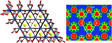
ACdCO3F (A = K and Rb): new noncentrosymmetric materials with remarkably strong second-harmonic generation (SHG) responses enhanced via π-interaction

Guohong Zoua, Gnu Namb, Hyung Gu Kima, Hongil Joa, Tae-Soo You*b and Kang Min Ok*a
aDepartment of Chemistry, Chung-Ang University, Seoul, 156-756, Republic of Korea
bDepartment of Chemistry, Chungbuk National University, Cheongju, Chungbuk 361-763, Republic of Korea. E-mail: kmok@cau.ac.kr; tsyou@chungbuk.ac.kr; Fax: +82 2 825 4736; Tel: +82 2 820 5197

Received 25th August 2015 , Accepted 30th September 2015

First published on 30th September 2015


Abstract

Two new noncentrosymmetric (NCS) materials, namely, ACdCO3F (A = K and Rb) containing both a d10 cation (Cd2+) and a π-conjugated parallel carbonate anion (CO32−), were synthesized through conventional solid state reactions. ACdCO3F exhibits a 3-dimensional structure that is composed of the stacked layers of [Cd(CO3)]. Each [Cd(CO3)] layer is connected by infinite Cd–F–Cd chains and the [CO3] triangles are oriented in the same direction with a coplanar alignment. KCdCO3F and RbCdCO3F reveal remarkably strong second-harmonic generation (SHG) responses of approximately 9.0 and 7.2 times that of potassium dihydrogen phosphate (KDP), respectively, and both materials are phase-matchable. ACdCO3F exhibit wide transparent regions ranging from far UV to mid IR. Theoretical calculations confirm that the large SHG efficiencies indeed originate from enhancement via interatomic interactions between the s and p states of Cd2+ and the π-conjugated groups of the [CO3]2− unit within the [Cd(CO3)] layers.


Introduction

The increasing importance of ultraviolet (UV) and deep-UV nonlinear optical (NLO) materials,1 as the key component of all-solid-state UV and deep-UV lasers, has prompted the continuous exploitation of new NLO crystals with high NLO coefficients and wide UV transparency. In general, a good UV or deep-UV NLO material should meet the following four criteria: (1) a relatively larger SHG coefficient (dij) than that of KDP; (2) a moderate birefringence (0.07–0.1) to achieve the phase matching condition in the UV region; (3) a wide UV transparency range and high damage threshold; and (4) good chemical stability and mechanical properties. Thus far, metal borates NLO materials,2 such as β-BaB2O4,2b LiB3O5,2c KBe2BO3F2,2d and SrBe2BO7,2e satisfying most of the above conditions have been the focus of intensive investigations. Over the last few decades, many efforts have been made to understand the relationship between the composition/structure and the NLO properties. According to the anionic group theory proposed by Chen,3 the boron–oxygen anionic groups have the dominant contribution to the macroscopic optical responses of the UV and deep-UV NLO borates. Several well-known examples of NCS borates are found from [B3O6]3− in β-BaB2O4,2b [B3O7]5− in LiB3O5,2c CsB3O5,2f and CsLiB6O10,2g,2h [BO3]3− in KBe2BO3F2,2d SrBe2BO7,2e K2Al2B2O7,2i and [BO4]5− in Li2B4O7.2j In particular, the planar [BO3]3− anionic group, with a moderate birefringence and a large microscopic second-order susceptibility β, is considered to be the best NLO basic structural unit for UV and deep-UV light generation.

Meanwhile, the [CO3]2− anionic group that is isoelectronic with [BO3]3− unit can also be used as a building block to design best performing UV NLO materials. In addition, most of carbonates possess good physical and chemical properties; thus, materials with [CO3]2− groups have invoked specific interests. In fact, several new carbonate NLO materials drawing much attention have been synthesized recently. Leblanc's group reported a series of NCS K4Ln2(CO3)3F4 (Ln = Nd, Sm, Eu and Gd).4 Ye's group introduced alkali metal fluorides into carbonates and successfully synthesized a family of novel fluoride carbonates, MNCO3F (M = K, Rb, Cs; N = Ca, Sr, Ba)5a which are promising UV NLO materials with moderate SHG coefficients. Ye and co-workers also discovered a few more NCS mixed metal fluoride carbonates such as Na8Lu2(CO3)6F2,5b Na3Lu(CO3)2F2,5b and CsPbCO3F.5c Halasyamani's group recently synthesized K2.70Pb5.15(CO3)5F3[thin space (1/6-em)]6a and RbPbCO3F6b along with a new deep-UV NLO material, RbMgCO3F.6c

It has been known that the increased density of the planar π-conjugated groups and its alignment could improve the NLO performance of extended solid state materials. Other well established noncentrosymmetric (NCS) chromophores that can enhance stronger SHG efficiencies in extended structures are found from the polar displacement of a d10 cation center7 and second-order Jahn–Teller (SOJT) distortive cations such as d0 transition metal cations with octahedral coordination environment and lone pair cations.1a,1b,8 A couple of successfully designed interesting NLO materials include Cd4BiO(BO3)3[thin space (1/6-em)]7a and CsPbCO3F.5c Guided by this idea, we introduced Cd2+ cation into carbonates for two reasons: (1) because Cd2+ is a divalent cation with the similar ionic radius to that of Ca2+, the coplanarity and alignment of [CO3]2− triangles can be easily maintained in the structure of KCaCO3F,5a which can result in a moderate birefringence for the phase matching condition in the UV region; (2) the polyhedra of d10 cation, Cd2+, can interact with the π-conjugated [CO3]2− units and may reveal synergistic polar displacement effect. Our investigations of the A−Cd–CO3–F (A = alkali metals) system resulted in two new alkali metal cadmium fluoride carbonates, i.e., ACdCO3F (A = K and Rb). Although the coordination environment of Cd2+ cation is highly symmetrical in the CdO6F2 polyhedron, it shows higher electronic deformation ability than that of KCaCO3F. We will demonstrate that the strong π-interaction between Cd2+ and [CO3]2− groups within the [Cd(CO3)] layers is responsible for the remarkable SHG response for the first time.

Experimental section

Synthesis

Polycrystalline samples of ACdCO3F (A = K and Rb) were synthesized through standard solid-state reactions. Stoichiometric amounts of KF (Alfa Aesar, 99%) or RbF (Alfa Aesar, 99%) and CdCO3 (Alfa Aesar, 99%) were thoroughly mixed with agate mortars and pestles and pressed into pellets. The pellets were heated at 320 °C for 80 h, and cooled down to room temperature rapidly at a rate of 10 °C min−1 with several intermediate grinding steps in between each heating. Synthesized NCS KCdCO3F and RbCdCO3F have been deposited to Noncentrosymmetric Materials Bank (http://ncsmb.knrrc.or.kr).

Powder X-ray diffraction (PXRD)

The PXRD data were collected on a Bruker D8-Advance diffractometer using Cu Ka radiation at room temperature with 40 kV and 40 mA. The 2θ range was 5–110° with a step size of 0.02°, and a step time of 1 s. The structures of the reported materials were refined using the Rietveld method with the GSAS program.9 The refinements of the products were carried out in the NCS space group, P[6 with combining macron]m2 (No. 187) with a starting model of the reported single-crystal data of KCaCO3F.5a The experimental, calculated, and difference diffraction plots for KCdCO3F and RbCdCO3F are shown in Fig. 1. The crystallographic data and refinement results of ACdCO3F (A = K and Rb) are summarized in Table 1. Atomic coordinates and isotropic displacement parameters of the reported materials can be found in the ESI.
image file: c5ra17209h-f1.tif
Fig. 1 Experimental, calculated, and difference X-ray diffraction plots for (a) KCdCO3F and (b) RbCd(CO3)3F. The calculated pattern (red solid line) is compared with the observed data (×). The locations of the reflections are indicated by the magenta vertical bars. The difference between the observed and calculated profiles is shown at the bottom (blue solid line).
Table 1 Summary of crystallographic data and refinement results of KCdCO3F and RbCdCO3F
Formula KCdCO3F RbCdCO3F
a Rp = Σ|IoIc|/ΣIo.b Rwp = [Σw|IoIc|2/ΣwIo2]1/2.
fw 230.51 276.88
Space group P[6 with combining macron]m2 P[6 with combining macron]m2
A = b Å−1 5.1287(2) 5.2101(2)
c 4.4277(2) 4.5293(2)
V3 100.86(11) 106.48(11)
Z 1 1
Rpa 0.1177 0.1012
Rwpb 0.1633 0.1140


Thermal analysis

The thermogravimetric analyses were performed with a Scinco TGA-N1000 thermal analyzer. Reference (Al2O3) and polycrystalline samples (5–15 mg) were enclosed in Al2O3 crucibles and heated from room temperature to 800 °C at a rate of 10 °C min−1 under a constant flow of argon gas. The TG residues were visually inspected and then analyzed by powder X-ray diffraction after the experiments.

Infrared (IR) spectroscopy

Infrared spectra of the samples were recorded on a Thermo Scientific Nicolet 6700 FT-IR spectrometer in the 400–4000 cm−1 ranges, with the samples embedded in KBr matrices.

UV-vis diffuse reflectance spectroscopy

UV-vis diffuse reflectance spectra were obtained on a Varian Cary 500 scan UV-vis-NIR spectrophotometer over the spectral range 200–2500 nm at room temperature. The reflectance spectra were transformed into absorbance using the Kubelka–Munk function.10

Second-harmonic generation (SHG) measurements

Powder SHG measurements were carried out using the experimental method adapted from that reported by Kurtz and Perry with 1064 nm radiation.11 Since SHG efficiencies were known to be strongly dependent on particle size, polycrystalline samples were ground and sieved into the following particle size ranges: 20–45, 45–63, 63–75, 75–90, 90–125, 125–150, 150–200, 250 mm. In order to make relevant comparisons with known SHG materials, crystalline KDP and KCaCO3F were also ground and sieved into the same particle size ranges. All of the sieved samples with different particle sizes were packed into distinct capillary tubes. The reflected green SHG light with 532 nm was collected and detected using a photomultiplier tube (Hamamatsu). To detect only the SHG light, a 532 nm narrow band-pass interference filter was attached to the front of the tube. The generated SHG signal was monitored using a digital oscilloscope (Tektronix TDS1032). This procedure was then repeated using the standard nonlinear optical materials, i.e., KDP and KCaCO3F, and the ratio of the second-harmonic intensity outputs was calculated. No index-matching fluid was used in any of the experiments. A detailed description of the methodology and the equipment used has been previously published.12

Computational details

Density functional theory (DFT) calculations for KCdCO3F and KCaCO3F were conducted by using the Stuttgart tight-binding linear muffin-tin orbital program (TB-LMTO47)13 with the atomic sphere approximation (ASA). Local density approximation (LDA)14 was employed to treat exchange and correlation, and a scalar relativistic approximation was used to take into account relativistic effects except spin–orbit coupling. In the ASA method, the space is filled with Wigner–Seitz (WS) atomic spheres,13 where the symmetry of the potential is considered spherical inside each WS sphere, and a combined correction is used to take into account the overlapping part.14 The radii of each WS sphere were determined by an automatic procedure14 and obtained by requiring the overlapping potential be the best possible approximation to the full potential. The overlap should not be too large since the error in kinetic energy introduced by the combined correction is proportional to the fourth power of the relative sphere overlap. Empty spheres should be exploited during the calculations. The used WS radii are as follows: K = 2.387 Å, Cd = 1.640 Å, C = 0.792 Å, O = 0.773 Å, and F = 1.083 Å for KCdCO3F; and K = 2.375 Å, Ca = 1.660 Å, C = 0.850 Å, O = 0.757 Å, and F = 1.070 Å for KCaCO3F. The used basis sets included 4s, 4p, 3d and 4f orbitals for K; 4s, 4p, 3d and 4f orbitals for Ca; 5s, 5p, 4d and 4f orbitals for Cd; 2s, 2p and 3d orbitals for C; 3s, 2p and 3d orbitals for O; and 3s, 2p, and 3d orbitals for F. The K 4p, 3d and 4f, Ca 4p, Cd 4f, C 3d, O 3s and 3d, and F 3s and 3d orbitals were treated by the Löwdin downfolding technique.15 The k-space integrations were conducted by the tetrahedron method,16 and the self-consistent charge densities for two calculations were obtained using 217 irreducible k-points in the Brillouin zone.

Results and discussion

Crystal structure description

KCdCO3F and RbCdCO3F exhibit similar structures to that of KCaCO3F5a and crystallize in the noncentrosymmetric hexagonal space group, P[6 with combining macron]m2 (No. 187). As seen in Fig. 2, ACdCO3F (A = K and Rb) reveal three-dimensional crystal structures consisting of corner-shared Cd(CO3)3F2 polyhedra. The Cd2+ cations are connected to carbonate groups in the ab-plane and are bridged through fluorides along the c-direction. The K+ or Rb+ cations are located in the cavities formed by the Cd(CO3)3F2 groups. In connectivity terms, the materials may be described as [Cd(CO3)3/3F2/2] anions, with the charge balance maintained by K+ or Rb+ cation. The C atom is coordinated to three O atoms to form a planar CO3 triangle with C–O bond lengths of 1.252(2) Å and 1.255(1) Å for KCdCO3F and RbCdCO3F, respectively. The cadmium atom is surrounded by six oxygen atoms and two fluorine atoms, forming a highly symmetrical CdO6F2 hexagonal bipyramid. The CdO6F2 hexagonal bipyramid shares its six equatorial oxygen atoms with three CO3 groups to form a flat CdCO3 layer and connects adjacent layers with its apical F atoms along the c-direction. Within a single CdCO3 layer (Fig. 2(b)), the cooperative connection of hexagonal CdO6 and triangular CO3 makes all CO3 groups aligned parallel in the ab-plane and oriented in the same direction. As we will describe more in detail later, the intermolecular interaction between the d10 cation, Cd2+, and the well aligned π-conjugated group, CO32−, are responsible for the large macroscopic SHG effect.
image file: c5ra17209h-f2.tif
Fig. 2 Ball-and-stick representations of KCdCO3F (a) viewed along the [100] direction and (b) the CdCO3 layer in the ab-plane (blue, Cd; yellow, K; red, O; green, F; gray, C). Note the Cd2+ cations exhibit the Cd(CO3)3F2 hexagonal bipyramidal coordination environment.

The bond valence sums for ACdCO3F (A = K and Rb) are calculated using the formula,

image file: c5ra17209h-t1.tif
where Sij is the bond valence associated with the bond lengths rij and r0, and B is an empirically determined parameter (usually 0.37).17 The calculated bond valence sums for K+, Rb+, Cd2+, and C4+ are 1.22, 1.39, 1.62–1.72, and 4.32–4.37, respectively.

Thermal properties

The thermogravimetric analyses (TGA) curves for both samples, KCdCO3F and RbCdCO3F, show single step weight losses (see Fig. 3). KCdCO3F is thermally stable up to 320 °C. After that it continually loses weight up to 400 °C. The observed total weight loss of 19.20% is very close to the calculated value of 19.09%. RbCdCO3F is also stable up to 350 °C, but then it continually loses weight up to 420 °C. The total weight loss of 15.62% is consistent with the calculated value of 15.89%. The weight losses correspond to the thermal decomposition of the compounds; in which 1 molecule of CO2 is released from each of the decomposition (see the following reaction). Thermally decomposed residuals were identified as CdO based on the powder X-ray diffraction patterns (see the ESI).
ACdCO3F (A = K and Rb) → AF + CdO + CO2 (g)

image file: c5ra17209h-f3.tif
Fig. 3 TGA diagrams of (a) KCdCO3F and (b) RbCdCO3F.

Infrared (IR) spectroscopy

The IR spectra of ACdCO3F (A = K and Rb) revealed C–O vibrations around 1500–650 cm−1. The strong broad bands observed at 1432 cm−1 for KCdCO3F and at 1442 cm−1 for RbCdCO3F can be assigned to the C–O stretching vibrations. The out-of-plane vibrations, δ (OCO), are also observed at 853 cm−1 for KCdCO3F and 843 cm−1 for RbCdCO3F as medium bands. The medium weak bands occurring at about 730–680 cm−1 can be assigned to the bending vibrations, δ (OCO). A strong band observed in the range of 730–680 cm−1 may be attributed to the overlap of the bending vibration, δ (OCO), and the stretching vibration, ν (Cd–O). The infrared spectra for the reported materials are presented in the ESI.

UV-vis diffuse reflectance spectroscopy

The UV-vis diffuse reflectance spectra were collected for ACdCO3F (A = K and Rb) (see Fig. 4). Absorption (K/S) data were calculated from the following Kubelka–Munk function:
image file: c5ra17209h-t2.tif
where R is the reflectance, K is the absorption, and S is the scattering.10 In the (K/S) versus E plots, extrapolating the linear part of the rising curve to zero provides the onset of absorption. The UV absorption spectra exhibit no absorption from 0.25 to 2.5 μm, suggesting that the materials have wide transparent regions ranging from far UV to mid-IR. The optical diffuse reflectance spectra indicate optical band gaps of 5.11 eV for KCdCO3F and 5.05 eV for RbCdCO3F.

image file: c5ra17209h-f4.tif
Fig. 4 UV-vis absorption spectra and optical diffuse reflectance spectra of KCdCO3F and RbCdCO3F.

Nonlinear optical (NLO) properties

The curves of SHG signal as a function of particle size from the measurements made on ground polycrystalline ACdCO3F (A = K and Rb) are shown in Fig. 5. The results are consistent with phase-matching behaviors according to the rule proposed by Kurtz and Perry (Fig. 5(b)).11 KDP and KCaCO3F were used as the reference. KCdCO3F exhibited very large SHG responses, ca. 9 times that of KDP (0.39 pm V−1, almost 3 times that of KCaCO3F).18 Also, the SHG efficiency of RbCdCO3F turned out to be ca. 7.2 times that of KDP (about 2.4 times that of KCaCO3F) (see Fig. 5(a)). It should be noted that the SHG efficiency of KCdCO3F is the largest reported to date among cadmium compounds containing the planar π-conjugated groups.
image file: c5ra17209h-f5.tif
Fig. 5 (a) Oscilloscope traces of the SHG signals for the powders (200–250 μm) of ACdCO3F (A = K and Rb), KDP, and KCaCO3F. (b) Phase-matching curves for ACdCO3F (A = K and Rb), KDP, and KCaCO3F using 1064 nm radiation.

Electronic structure calculations

A series of theoretical calculations has been conducted for the title compound KCdCO3F by using TB-LMTO-ASA method13 to understand the influence of interatomic interactions between Cd2+ cations and the [CO3]2− units on the [Cd(CO3)] layers for the remarkably enhanced SHG response of KCdCO3F. Total and partial density of states (DOS) curves19 were thoroughly analyzed to understand atomic orbital distributions over the whole energy range, and crystal orbital Hamilton population (COHP) curves19 were examined as well to study chemical bonding in the structure. Electron localization functions (ELF)20 visualized the paired electron densities of the interatomic interactions of our interests. KCaCO3F was also theoretically interrogated for the comparison with the title compound. All details about crystal structures of two compounds were extracted, respectively, from the refinement result of powder X-ray diffraction data of KCdCO3F and the result of single crystal X-ray diffraction data of KCaCO3F.

We were particularly interested in the crystallographic ab-plane with y = 0.5, the (002) plane, where both Cd2+ cations and the [CO3]2− units showed the coplanar alignment and were oriented toward the same direction. In particular, the [CO3]2− unit had the triangular-shaped local geometry with the D3h symmetry, in which one C atom was located at the center and three O atoms occupied vertices of the triangle. The textbook patterns of DOS curves of the D3h symmetry for the [CO3]2− units are clearly observed in Fig. 6. The overall total DOS (TDOS) curves display a complex orbital mixing among all three elements. The valence band region below the Fermi level (EF) can be divided into three sections in terms of atomic orbital contributions (see Fig. 6(a)): (1) the section between −9.8 and −6.5 eV includes major contributions from the s, px, and py states of both C and O forming the σ-bond via the sp2-hybridization, (2) the section between −5.0 and −1.5 eV displays contributions mostly originated from the pz state of the central C and the pz group orbitals of three surrounding O, which eventually form the π-bonding and π*-antibonding in the [CO3]2− unit (see Fig. 6(b) and (c)), and (3) the region between −1.0 and EF represents dominant contributions from the nonbonding group orbitals of three O atoms.


image file: c5ra17209h-f6.tif
Fig. 6 TDOS curves of KCdCO3F. (a) Total DOS (black-bold line), K PDOS (gray region), Cd PDOS (green region), C PDOS (dark-red region), O PDOS (yellow region), and F PDOS (orange region). EF is indicated as the vertical dashed line and the energy reference (0 eV). PDOS curves of the selected orbitals for C (b), O (c), and Cd (d), respectively.

As partial DOS (PDOS) curves of Cd (Fig. 6(d)) are projected on PDOS of the just discussed [CO3]2− unit (Fig. 6(b) and (c)), we can surely realize that the localized d states of Cd appear in the particular region, where the s and p states of both C and O display the major contributions resulting in the σ-bond. On the other hand, the location of the s and p states of Cd overlaps with that of the pz states of both C and O contributing to the π-bond in the [CO3]2− unit. It is noteworthy to mention that due to the electronegativity difference between C and O as well as the energy difference of atomic orbitals of C and O, the π-bond contains the larger contribution from O than C. Therefore, this observation implies that a certain degrees of interatomic interactions should exist between Cd2+ and the π-conjugated orbitals of the [CO3]2− unit, and the COHP curves shown in the ESI well support our interpretation.

This type of particular interatomic interaction on the [Cd(CO3)] layers can be visualized by the electron localization function (ELF) diagrams. The ELF has been known to clearly illustrate the paired-electron densities observed in bonding pairs and lone pairs.20 As mentioned earlier, the sliced (002) plane was selected for our ELF diagram since both Cd2+ and the [CO3]2− unit were located. For the comparison, the ELF plot of the sliced (002) plane for KCaCO3F was also displayed in Fig. 7. Firstly, the σ-type interactions within the [CO3]2− unit for both compounds display the nearly identical ELF plot, where large attractors are localized around the [CO3]2− unit and Cd2+, separately (see Fig. 7(a) and (c)). On the other hand, the π-type interactions inside the [CO3]2− unit indicate distinctive electron densities for two compounds: the π-conjugated groups of the [CO3]2− unit in KCdCO3F spread further out toward Cd2+ illustrating certain degrees of interactions between Cd2+ and the [CO3]2− unit (see Fig. 7(b)), whereas those in KCaCO3F are still confined around the [CO3]2− unit (see Fig. 7(d)). Therefore, the enhanced SHG response of KCdCO3F should be attributed to the strengthened interatomic interactions between the s and p states of Cd2+ and the π-conjugated groups of the [CO3]2− unit.


image file: c5ra17209h-f7.tif
Fig. 7 The electron localization function (ELF) diagrams representing the σ- and the π-bond of KCdCO3F ((a) and (b)), and KCaCO3F ((c) and (d)), respectively. The diagrams display sliced-planes of ELF along the (002) direction as contour maps. The color scheme ranges from blue to red (0–0.9), and values higher than 0.5 represent the area exceeding free-electron ELF value.

Structure-NLO properties relationships

KCdCO3F and RbCdCO3F crystallize in the NCS nonpolar space group. With the polar materials containing SOJT distortive cations, it has been known that the SHG efficiencies are strongly influenced by the direction and the magnitude of the net moment of polar structural units. However, with the nonpolar materials, the NLO responses of the NCS crystals to an external optical electric field are closely related to the induced dipole oscillations in the lattice. In other words, the compliance of the dipole moment, rather than the intrinsic dipole moment itself, determines the SHG efficiency. Since the compliance of the dipole moment results from the flexibility of the electronic motion in a chemical bond subjected to the perturbation of the external optical electric field, the more “flexible” the chemical bonds in the microscopic groups are, the larger SHG effect in a crystal will be, provided the resulting second-order susceptibility can be additively superposed. On the basis of the anionic group theory, the contribution to the main SHG coefficients of ACdCO3F (A = K and Rb) from the anionic group [CO3]2− is dominant. In the structure of ACdCO3F, as we explained in the electronic structure calculations section, the cooperative connection of hexagonal CdO6 and triangular CO3 makes all CO3 groups aligned parallel in the ab-plane and oriented in the same direction, giving a 100% optimum to maximize contribution to a large macroscopic SHG effect. In comparison with its isostructural compound KCaCO3F, the sharp SHG increase for ACdCO3F may have come from polar displacement of a d10 cation, Cd2+, center as expected. By theoretical calculations, we confirm that the large SHG efficiencies of ACdCO3F (A = K and Rb) originate from the enhancement via interatomic interactions between the s and p states of Cd2+ and the π-conjugated groups of the [CO3]2− unit within the [Cd(CO3)] layers. However, no interatomic interaction between Ca2+ and the π-conjugated groups of the [CO3]2− unit in KCaCO3F is observed.

KCdCO3F reveals a bit larger SHG efficiency compared to that of RbCdCO3F. The difference may be attributed to the larger polarizability of Rb+ cations that are hampering effective interactions between Cd2+ and asymmetric π-systems. ACdCO3F (A = K and Rb), however, reveal weaker SHG efficiencies compared to that of CsPbCO3F,5c although they do exhibit similar crystal structures. More narrow energy gap of CsPbCO3F (4.15 eV) compared to that of KCdCO3F (5.11 eV) or RbCdCO3F (5.05 eV) may results in a stronger interaction between the valence and conduction bands, which can provide extra flexibility of the electronic motion in the delocalized bonds.

Conclusions

Two phase-matchable NCS compounds, KCdCO3F and RbCdCO3F with large powder SHG coefficients and wide transparent regions ranging from far UV to mid IR have been synthesized and characterized. Theoretical analyses reveal that the π-interaction between Cd2+ and [CO3]2− groups within the [Cd(CO3)] layers are responsible for the remarkable SHG responses. Thus, the reported materials are expected to be promising UV nonlinear optical materials. The growths of large single crystals are ongoing for further physical property measurements.

Acknowledgements

This work was supported by the National Research Foundation of Korea (NRF) grant funded by the Korea government (No. 2014M3A9B8023478 and 2014H1C1A1066874). G.Z. thanks the National Natural Science Foundation of China (No. 21401178).

Notes and references

  1. (a) P. S. Halasyamani and K. R. Poeppelmeier, Chem. Mater., 1998, 10, 2753 CrossRef CAS; (b) H. S. Ra, K. M. Ok and P. S. Halasyamani, J. Am. Chem. Soc., 2003, 125, 7764 CrossRef CAS PubMed; (c) R. E. Sykora, K. M. Ok, P. S. Halasyamani and T. E. Albrecht-Schmitt, J. Am. Chem. Soc., 2002, 124, 1951 CrossRef CAS PubMed; (d) H. Ye, D. Fu, Y. Zhang, W. Zhang, R. G. Xiong and S. D. Huang, J. Am. Chem. Soc., 2009, 131, 42 CrossRef CAS PubMed; (e) S. C. Wang, N. Ye, W. Li and D. Zhao, J. Am. Chem. Soc., 2010, 132, 8779 CrossRef CAS PubMed; (f) S. C. Wang and N. Ye, J. Am. Chem. Soc., 2011, 133, 11458 CrossRef CAS PubMed; (g) Y. Z. Huang, L. M. Wu, X. T. Wu, L. H. Li, L. Chen and Y. F. Zhang, J. Am. Chem. Soc., 2010, 132, 12788 CrossRef CAS PubMed; (h) F. Kong, S. P. Huang, Z. M. Sun, J.-G. Mao and W. D. Cheng, J. Am. Chem. Soc., 2006, 128, 7750 CrossRef CAS PubMed; (i) H. Y. Chang, S. H. Kim, P. S. Halasyamani and K. M. Ok, J. Am. Chem. Soc., 2009, 131, 2426 CrossRef CAS PubMed; (j) C. F. Sun, C. L. Hu, X. Xu, J. B. Ling, T. Hu, F. Kong, X. F. Long and J.-G. Mao, J. Am. Chem. Soc., 2009, 131, 9486 CrossRef CAS PubMed; (k) E. O. Chi, K. M. Ok, Y. Porter and P. S. Halasyamani, Chem. Mater., 2006, 18, 2070 CrossRef CAS; (l) S. L. Pan, J. P. Smit, B. Watkins, M. R. Marvel, C. L. Stern and K. R. Poeppelmeier, J. Am. Chem. Soc., 2006, 128, 11631 CrossRef CAS PubMed; (m) S.-W. Bae, C.-Y. Kim, D. W. Lee and K. M. Ok, Inorg. Chem., 2014, 53, 11328 CrossRef CAS PubMed; (n) G. Zou, Z. Ma, K. Wu and N. Ye, J. Mater. Chem., 2012, 22, 19911 RSC; (o) L. Huang, G. Zou, H. Cai, S. Wang, C. Lin and N. Ye, J. Mater. Chem. C, 2015, 3, 5268 RSC.
  2. (a) P. Becker, Adv. Mater., 1998, 10, 979 CrossRef CAS; (b) C. T. Chen, B. C. Wu, A. D. Jiang and G. M. You, Sci. Sin., Ser. B, 1985, 28, 235 Search PubMed; (c) C. T. Chen, Y. C. Wu, A. D. Jiang, B. C. Wu, G. M. You, R. K. Li and S. J. Lin, J. Opt. Soc. Am. B, 1989, 6, 616 CrossRef CAS; (d) L. Mei, Y. Wang, C. Chen and B. Wu, J. Appl. Phys., 1993, 74, 7014 CrossRef CAS PubMed; (e) C. T. Chen, Y. B. Wang, B. C. Wu, K. C. Wu, W. L. Zeng and L. H. Yu, Nature, 1995, 373, 322 CrossRef CAS PubMed; (f) Y. C. Wu, T. Sasaki, S. Nakai, A. Yokotani, H. G. Tang and C. T. Chen, Appl. Phys. Lett., 1993, 62, 2614 CrossRef CAS PubMed; (g) Y. Mori, I. Kuroda, S. Nakajima, T. Sasaki and S. Nakai, Appl. Phys. Lett., 1995, 67, 1818 CrossRef CAS PubMed; (h) J. M. Tu and D. A. Keszler, Mater. Res. Bull., 1995, 30, 209 CAS; (i) Z. G. Hu, T. Higashiyama, M. Yoshimura, Y. K. Yap, Y. Mori and T. Sasaki, Jpn. J. Appl. Phys., 1998, 37, 1093 CrossRef; (j) R. Komatsu, Appl. Phys. Lett., 1997, 70, 3492 CrossRef CAS PubMed; (k) H. Wu, S. Pan, K. R. Poeppelmeier, H. Li, D. Jia, Z. Chen, X. Fan, Y. Yang, J. M. Rondinelli and H. Luo, J. Am. Chem. Soc., 2011, 133, 7786 CrossRef CAS PubMed; (l) Y. Shi, S. Pan, X. Dong, Y. Wang, M. Zhang, F. Zhang and Z. Zhou, Inorg. Chem., 2012, 51, 10870 CrossRef CAS PubMed; (m) X. Xu, C.-L. Hu, F. Kong, J.-H. Zhang, J.-G. Mao and J. Sun, Inorg. Chem., 2013, 52, 5831 CrossRef CAS PubMed; (n) X. Fan, L. Zang, M. Zhang, H. Qiu, Z. Wang, J. Yin, H. Jia, S. Pan and C. Wang, Chem. Mater., 2014, 26, 3169 CrossRef CAS; (o) J.-L. Song, C.-L. Hu, X. Xu, F. Kong and J.-G. Mao, Angew. Chem., Int. Ed., 2015, 54, 3679 CrossRef CAS PubMed; (p) H. P. Wu, S. L. Pan, K. R. Poeppelmeier, H. Y. Li, D. Z. Jia, Z. H. Chen, X. Y. Fan, Y. Yang, J. M. Rondinelli and H. S. Luo, J. Am. Chem. Soc., 2011, 133, 7786 CrossRef CAS PubMed; (q) H. W. Yu, S. L. Pan, H. P. Wu and Z. H. Yang, J. Mater. Chem., 2012, 22, 2105 RSC; (r) H. W. Yu, H. P. Wu, S. L. Pan, Z. H. Yang and K. R. Poeppelmeier, J. Am. Chem. Soc., 2014, 136, 1264 CrossRef CAS PubMed.
  3. (a) C. T. Chen, Sci. Sin., 1979, 22, 756 CAS; (b) C. T. Chen and G. Z. Liu, Annu. Rev. Mater. Sci., 1986, 16, 203 CrossRef CAS; (c) C. T. Chen, Y. C. Wu and R. K. Li, Int. Rev. Phys. Chem., 1989, 8, 65 CrossRef CAS PubMed.
  4. N. Mercier, M. Leblanc and J. Durand, Eur. J. Solid State Inorg. Chem., 1997, 34, 241 CAS.
  5. (a) G. Zou, N. Ye, L. Huang and X. S. Lin, J. Am. Chem. Soc., 2011, 133, 20001 CrossRef CAS PubMed; (b) M. Luo, G. Zou, N. Ye, C. S. Lin and W. D. Cheng, Chem. Mater., 2013, 25, 3147 CrossRef CAS; (c) G. Zou, L. Huang, N. Ye, C. S. Lin, W. D. Cheng and H. Huang, J. Am. Chem. Soc., 2013, 135, 18560 CrossRef CAS PubMed.
  6. (a) T. Tran and P. S. Halasyamani, Inorg. Chem., 2013, 52, 2466 CrossRef CAS PubMed; (b) T. Tran, P. S. Halasyamani and J. M. Rondinelli, Inorg. Chem., 2014, 53, 6241 CrossRef CAS PubMed; (c) T. T. Tran, J. He, J. M. Rondinelli and P. S. Halasyamani, J. Am. Chem. Soc., 2015, 137, 10504 Search PubMed.
  7. (a) W. L. Zhang, W. D. Cheng, H. Zhang, L. Geng, C. S. Lin and Z. Z. He, J. Am. Chem. Soc., 2010, 132, 1508 CrossRef CAS PubMed; (b) Y. Inaguma, M. Yoshida and T. Katsumata, J. Am. Chem. Soc., 2008, 130, 6704 CrossRef CAS PubMed.
  8. D. Phanon and I. Gautier-Luneau, Angew. Chem., Int. Ed., 2007, 46, 8488 CrossRef CAS PubMed.
  9. A. C. Larson and R. B. von Dreele, General Structural Analysis System (GSAS), Los Alamos National Laboratory, Los Alamos, NM, 1987 Search PubMed.
  10. (a) P. Kubelka and F. Z. Munk, Tech. Phys., 1931, 12, 593 Search PubMed; (b) J. Tauc, Mater. Res. Bull., 1970, 5, 721 CrossRef CAS.
  11. S. K. Kurtz and T. T. Perry, J. Appl. Phys., 1968, 39, 3798 CrossRef CAS PubMed.
  12. K. M. Ok, E. O. Chi and P. S. Halasyamani, Chem. Soc. Rev., 2006, 35, 710 RSC.
  13. (a) O. K. Andersen, Phys. Rev. B: Condens. Matter Mater. Phys., 1975, 12, 3060 CrossRef CAS; (b) O. K. Andersen and O. Jepsen, Phys. Rev. Lett., 1984, 53, 2571 CrossRef CAS; (c) O. K. Andersen, Phys. Rev. B: Condens. Matter Mater. Phys., 1984, 34, 2439 Search PubMed; (d) O. Jepsen, A. Burkhardt and O. K. Andersen, The TB-LMTO-ASA Program, version 4.7, Max-Plank-Institut fur Festkorperforschung, Stuttgart, Germany, 1999 Search PubMed; (e) O. K. Andersen, O. Jepsen and D. Glötzel, Highlights of Cendensed Matter Theory, North Holland, New York, 1985 Search PubMed.
  14. O. Jepsen and O. K. Andersen, J. Phys. Chem. B, 1995, 97, 35 CAS.
  15. R. Dronskowski and P. E. Blöchl, J. Phys. Chem., 1993, 97, 8617 CrossRef CAS.
  16. P. E. Blöchl, O. Jepsen and O. K. Andersen, Phys. Rev. B: Condens. Matter Mater. Phys., 1994, 49, 16223 CrossRef.
  17. (a) I. D. Brown and D. Altermatt, Acta Crystallogr., Sect. B, 1985, 41, 244 CrossRef; (b) N. E. Brese and M. O'Keeffe, Acta Crystallogr., Sect. B, 1991, 47, 192 CrossRef.
  18. R. C. Eckardt, H. Masuda, Y. X. Fan and R. L. Byer, IEEE J. Quantum Electron., 1990, 26, 922 CrossRef CAS.
  19. R. Dronskowski and P. Blӧchl, J. Phys. Chem., 1993, 97, 8617 CrossRef CAS.
  20. (a) M. V. Putz, Int. J. Quantum Chem., 2005, 105, 1 CrossRef CAS PubMed; (b) E. Jang, G. Nam, H. Woo, J. Lee, M.-K. Han, S.-J. Kim and T.-S. You, Eur. J. Inorg. Chem., 2015, 17, 2786 CrossRef PubMed; (c) H. Woo, G. Nam, E. Jang, J. Kim, Y. Lee, K. Ahn, S. Bobev and T.-S. You, Inorg. Chem., 2014, 53, 4669 CrossRef CAS PubMed.

Footnote

Electronic supplementary information (ESI) available: Atomic coordinates and isotropic displacement parameters, selected bond distances and angles, infrared spectra, PXRD patterns of thermal decomposition products, and COHP curves for KCdCO3F and RbCdCO3F. See DOI: 10.1039/c5ra17209h

This journal is © The Royal Society of Chemistry 2015