
Influence of aliovalent cation substitution on structural and electrical properties of Gd2(Zr1−xMx)2O7−δ (M = Sc, Y) systems†
Vaisakhan Thampi D. S.,
Prabhakar Rao Padala* and
Renju U. A.
Materials Science and Technology Division, National Institute for Interdisciplinary Science and Technology (NIIST), Trivandrum, India-695019. E-mail: padala_rao@yahoo.com; Fax: +91 471 2491712; Tel: +91 471 2515311
First published on 13th October 2015
Abstract
Fluorite-type zirconate compositions of the form Gd2(Zr1−xMx)2O7−δ (M = Sc and Y; x = 0, 0.1, 0.2, 0.3, 0.4) were prepared by a solid state reaction route and the influence of aliovalent cation substitution on the structural and electrical properties were investigated using powder X-ray diffraction, Raman spectroscopy, transmission and scanning electron microscopy and impedance spectroscopy techniques. Despite being in the same group of elements, the two substituent cations introduced oxygen vacancies with contrasting influence on the parent lattice and ionic conductivity. The larger ionic radius of Y3+ forced the lattice to expand which along with the increased anion defects lowered the energy barrier for charge transport enhancing the ionic conductivity. Whereas, in Sc-substituted compositions, oxygen vacancies dominated over ionic size causing the lattice to contract and their cooperative behavior turned out to be disadvantageous for long range conduction processed with increased activation energies resulting in lowering the ionic conductivity. The changes in rigidity of the inter-ionic bonds and the lattice volume introduced by the substituent cations also influenced the thermal expansion behavior of the materials. This work demonstrates that the influence of oxygen vacancies on the ionic conductivity is also dependent on the size of the aliovalent substituent ion.
Introduction
On the backdrop of diminishing energy resources, a quest for efficient solid oxide electrolyte materials to be used for fuel cell applications has been taking place over the last few decades. The electrolyte is the heart of a solid oxide fuel cell.1 Since fuel cells constitute a promising category of non-conventional energy resources, material development for them, especially electrolytes, has gained much attention.2,3 The electrolyte materials should possess some specific features like high electrical conductivity, adequate thermal and mechanical properties like strength, creep, etc., thermodynamic and structural stability.4 Apart from this, properties like thermal expansion should match with the other fuel cell components, which poses limitations in changing to completely new ceramic systems.1Various zirconate ceramics having a general formula A2B2O7 have been studied extensively in this respect wherein attempts to enhance the electrical properties have been made by means of substitution or addition of foreign cations in already known chemical systems.5–9 These zirconate compositions mostly crystallize in either a pyrochlore-type or a fluorite-type lattice depending on the difference in size between the two cations.10 The larger the ionic size difference, higher will be the structural order within the lattice and the ordering or disordering transitions between the two structures induced by cation-substitution are found to have some influence on the electrical properties of these compounds.11–13 Among the various zirconate systems reviewed, Gd2Zr2O7 is reported to be one of the best with respect to the electrical characteristics.14–16 It is known to exist both in fluorite and pyrochlore structures with various preparation conditions.17 There have also been many attempts to tailor the properties of this chemical system with varying results, some being positive and some negative.14–16,18–20 Substitution of Gd3+ by Sm3+ and then co-substitution by Ca2+ had positive effects on the properties of parent composition.19,21 Substitution by Eu3+ also was helpful for improved electrical properties.16 Nb5+ while substituting Zr4+ led to an enhancement in the electrical conductivity whereas Ce4+ and Mo6+ in that place were found to bring it down.15,20,22 In most of these studies, there were certain optimum levels of substitution that corresponded to the maximum value of conductivity, which depended on many other factors like lattice order, lattice volume, point defects, etc. Thus, despite extensive attempts, there does not exist any general rule that can guide to the best direction to achieve desired properties.
Since defect-fluorite structures involve more than one type of cations, they can inherently contain some amount of order. Most of the aforementioned substitution attempts are focused on the A-cation site. Here in the present work two cations, Sc3+ and Y3+, were independently chosen to substitute the Zr4+ partially in the B-site of Gd2Zr2O7. The differences in ionic size can influence the crystal order and the lattice volume. That, along with the difference in valence, was expected to influence various physical properties. Crystal structure and electrical properties were given prime focus in the present investigation. The independent substitution would help to contrast between ions and to understand the various mechanisms distinctly.
Experimental
Solid solutions of general formula Gd2(Zr1−xMx)2O7−δ (M = Sc, Y; x = 0, 0.1, 0.2, 0.3, 0.4) were prepared. Conventional solid state reaction route involving choice of oxides of the cations as reactants and wet mixing followed by heat treatment was adopted for the synthesis of the samples. Homogenous mixture of Gd2O3 (Aldrich, 99.9%), ZrO2 (Aldrich, 99%), Sc2O3 (Alfa Aesar, 99.99%) and Y2O3 (Sigma-Aldrich, 99.99%) weighed according to stoichiometry was calcined at 1300 °C and recalcined at 1600 °C, both for 6 h each. The product powders were then made to green pellets with a hydraulic press applying uniaxial compaction at 2.5 MPa. The pellets were then sintered at 1650 °C for 24 h.The prime tool to investigate structural features was an X-ray diffractometer (X'Pert Pro, PANalytical) making use of Cu Kα radiation of wavelength 1.54 Å. The diffractograms were recorded in a 2θ range of 10° to 90°. FT-Raman spectra of samples were obtained by exciting with an argon laser of wavelength 784 nm using a Labram HR 800 spectrometer (Horiba Scientific). Morphological features were examined through electron microscopic technique, namely a scanning electron microscope (SEM, model: JEOL JSM-5600LV) and a transmission electron microscope (TEM, TECNAI 30 G2 S-TWIN, the Netherlands), which were also helpful in confirming the crystallinity of prepared samples. The response of the crystals to high temperature was analyzed through high-temperature X-ray diffraction (Anton-Paar high-temperature attachment to XRD). Impedance spectroscopy was used to probe the electrical properties. Cylindrical pellets were subjected to two-point impedance measurement using an impedance analyzer (Solartron SI 1260) through a dielectric interface (Solartron 1296). Electroding was done at polished end-faces painted with silver-paste and the measurement frequency was varied from 1 MHz to 1 Hz, in a temperature range of 473 K to 1023 K.
Results and discussion
In coming sections, the Sc3+ and Y3+ substituted samples of the form Gd2(Zr1−xMx)2O7−δ (M = Sc, Y; x = 0, 0.1, 0.2, 0.3, 0.4) will be respectively labelled with the codes GZS and GZY with a numeral representing the value of x for each sample. GZ will stand for Gd2Zr2O7.Crystal structure
Powder X-ray diffraction was made use of to understand the maximum feasibility of solid solution formation and to analyze the crystal structure of the synthesized materials. Sharp X-ray reflections could be seen in the recorded diffraction pattern that indicated the crystalline nature of the samples. A comparison with standard ICDD powder pattern no. 01-080-0471 showed that all the single phase compositions crystallized in a cubic fluorite-type structure with Fm3m space group.In the cubic fluorite-type crystals, the cations constitute a face centered lattice and are cubically coordinated by eight anions as shown in Fig. 1. The anions, whereas, are coordinated by four cations which form a tetrahedron about each of them. The crystallographically different lattice positions are designated by Wyckoff notations 4a (0, 0, 0) and 8c (0.25, 0.25, 0.25) occupied respectively by cations and anions. In Gd2Zr2O7, which is considered to be a defect fluorite-type crystal, the Gd and Zr ions are disordered over an fcc lattice. The XRD patterns of the Gd2(Zr1−xMx)2O7−δ compositions are shown in Fig. 2 and 3. It could be observed that the Gd2Zr2O7 lattice accommodated the aliovalent M ion (M = Sc3+, Y3+) in the Zr4+ site to a fairly good extent of x = 0.3. Although both Sc3+ and Y3+ showed maximum solubility in solid solution formation at x = 0.3, a close observation of the peak patterns showed that the overall influence the substitution had on the crystal structure was different from one another.
 | ||
| Fig. 1 Cubic fluorite structure. Blue spheres represent cations and red spheres represent anions. The polyhedra represent the coordination environments of both species. | ||
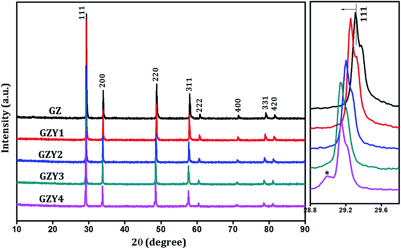 | ||
| Fig. 2 Powder X-ray diffraction patterns of Gd2(Zr1−xYx)2O7−δ. Side panel shows the expanded view of (111) peak. | ||
 | ||
| Fig. 3 Powder X-ray diffraction patterns of Gd2(Zr1−xScx)2O7−δ. Side panel shows the expanded view of (111) peak. | ||
With substitution of Zr4+ by Y3+, the X-ray reflections were found to shift towards lower angles as seen in the side panel of Fig. 2, indicating an increase in the interplanar spacing of various miller planes. But the trend observed for substitution by Sc3+ was different, and there the reflections moved towards higher angles (as in Fig. 3) with increasing amount of substitution. In both cases there was no appreciable change in the width of diffraction peaks.
A more detailed and quantitative analysis of the XRD data was carried out by Rietveld simulation and refinement method using commercially available X'pert Highscore plus23 software. A standard peak-matching procedure with the ICDD crystal structure database helped constructing starting models for pattern simulation, with the stoichiometry providing an intuitive idea about the ionic occupancies. Fitting of diffraction peaks demanded a pseudo-Voigt line profile function which is essentially a linear combination of Gaussian and Lorentzian functions. The Caglioti parameters, flat background and two background function coefficients were chosen for refinement along with the unit cell identities. Relevant results from the best-fit refinement of various samples are listed in Table 1.
| GZ | GZY1 | GZY2 | GZY3 | GZY4 | GZS1 | GZS2 | GZS3 | |
|---|---|---|---|---|---|---|---|---|
| Unit cell | Cubic | Cubic | Cubic | Cubic | Cubic | Cubic | Cubic | Cubic |
| Space group | Fm3m | Fm3m | Fm3m | Fm3m | Fm3m | Fm3m | Fm3m | Fm3m |
| Scale factor | 0.000181 | 0.000187 | 0.000158 | 0.000161 | 0.000133 | 0.000181 | 0.000175 | 0.000164 |
| Cell a [Å] | 5.2729(1) | 5.2831(1) | 5.2932(1) | 5.3011(1) | 5.3028(2) | 5.2659(1) | 5.2581(1) | 5.2516(1) |
| Rp (%) | 6.45 | 6.23 | 6.15 | 6.02 | 6.91 | 6.04 | 5.48 | 5.84 |
| Rexp (%) | 6.76 | 6.63 | 6.88 | 6.84 | 7.21 | 6.89 | 7.15 | 7.13 |
| Rwp (%) | 9.2 | 8.65 | 7.93 | 7.64 | 8.97 | 7.9 | 7.01 | 7.43 |
| GOF | 1.87 | 1.7 | 1.32 | 1.24 | 1.54 | 1.31 | 0.96 | 1.08 |
It can be observed from the result of Rietveld refinement that the influence on the fundamental lattice vector of the Gd2Zr2O7 lattice is different for Sc and Y ions. While considering the lattice volume in substitution processes, the most commonly reported influence comes from the radius of the substituent ion. According to Vegard's law,24 a larger ion substituting a smaller ion is expected to increase the lattice volume and vice versa. The ionic radii of Gd3+, Zr4+, Sc3+ and Y3+ under the eight-coordination condition in a fluorite type lattice are 1.053 Å, 0.84 Å, 0.87 Å and 1.019 Å respectively.25 Although both these substituent cations are larger in radius than Zr4+, substitution by Sc3+ decreases the effective lattice parameter while substitution by Y3+ increases it.
For Y3+ substitution, the incorporation of larger ions into the 4a sites previously occupied by smaller Zr4+ ions forces the lattice to expand. This is evident in Fig. 4(a) where there is a linear increase in the lattice parameter with increase in Y3+ substitution. For the GZY4 sample, the peak is seen to swerve from this trend. This may be because, beyond the limit of solubility, substituent ions tend to form other impurity phases without causing much strain to the parent lattice. The last data point of the lattice parameter plot in Fig. 4(a) illustrates this, where the increase in lattice parameter beyond x = 0.3 is comparatively very less.
 | ||
| Fig. 4 Variation of lattice parameter with substitution for (a) GZY series (b) GZS series. | ||
On the contrary, the lattice parameter is decreasing with substitution by Sc3+ as evident in Fig. 4(b). This may be attributed to the effect of Schottky defects in the anionic sublattice caused by aliovalent substitution. When tetravalent Zr is substituted by trivalent Sc, oxygen vacancies will be created in the lattice for electrostatic balance. Substitution of every two Zr ions will create one oxygen vacancy in the vicinity, and can be represented in Kroger–Vink notation as

This will reduce the average coordination number of the 4a site cation which is 8 for an ideal fluorite-type lattice. Marrochelli et al. established through molecular dynamics simulation and a meta-analysis of literature that the size of an oxygen vacancy is smaller than an oxygen ion.26 They report that for host cations smaller than Ce4+ in fluorite-structure, the asymmetric cation relaxations around an oxygen vacancy can lead to a significant contraction of the lattice.27 This is observed by the shift of X-ray reflection peaks towards higher angles. Such an effect has been observed in some other similar chemical systems too.28,29 A close examination of the XRD patterns showed that there is no considerable change in the width of diffraction peaks with respect to both substitutions. Instrumental broadening, crystallite size effect and lattice strain are the key factors that contribute to the line width in diffraction pattern. Since the first two factors were made as equivalent as possible for all the samples through same measurement conditions and similar crystallite sizes, any change in the line width could be loosely attributed to the lattice strain. Absence of such an effect may be indicating that the substitution process does not introduce much strain to the lattice. In this context, it is reasonable to assume that when the cationic size difference is comparatively smaller, the effect of oxygen vacancies becomes dominant as far as substitution by Sc3+ and Y3+ are compared.
A parallel way to understand the structural influence of the ionic substitution was attempted through FT-Raman analysis. In the cubic fluorite structure, the site symmetry of the 4a site cation is Oh and that of the 8c anion is Td.30 Factor group analysis had shown that an ideal cubic fluorite lattice would possess only one Raman active mode T2g which is generally found at ∼470 cm−1.31–33
However in Fig. 5, more than one peak could be distinguished in the Raman spectra which are generally broad in nature. The broad nature of Raman modes cannot be a result of small crystallite size since the sharp X-ray reflections and the images in the SEM and TEM analyses indicate the contrary. The broadness is a result of inherent deviations from the translational periodicity in the lattice of a disordered fluorite structure.34–36 Presence of some additional vibrations below and above the T2g frequency can be justified by acknowledging the deviation of the present system from an ideal fluorite lattice. In such defect fluorite-type crystals some degree of ordering will always be present due to the different cations occupying the same crystallographic site and this is expected to give rise to some additional vibrational modes as visible in Fig. 5.31,33 As observed in the present system, T2g mode in defect fluorites is reported to be generally very weak and broad in nature.12,37 Broadening of vibrational modes is often an indication of increasing disorder in a crystal lattice. The cationic size difference is a crucial factor deciding the extent of order in fluorite-related structures like pyrochlores. In pyrochlore type structures with a general formula A2B2O7, the ratio of radii of A and B cations (rA/rB) gives a measure of order. In the discussions regarding the order–disorder transitions in such chemical systems, ordered pyrochlore structure is said to be stable in the rA/rB range of 1.76 to 1.46 and a decrease in rA/rB is a driving factor of disorder.11,38,39 Considering the size of the cations involved in the present system, it can be inferred that substitution by Sc and Y, both being larger than Zr and smaller than Gd, would in effect bring down the cationic size difference in the lattice thereby leading to more disorder. This can be understood from the observation that Y3+ substituted system, it being the larger of the two substituent cations, shows more broadening than the Sc3+ substituted one.34
 | ||
| Fig. 5 FT-Raman spectra showing the effect of cation substitution. | ||
A contrast between two substitutions is seen when the peak position is analyzed. With Sc-substitution, the T2g mode is found to show a small positive shift in frequency whereas with Y-substitution it is showing a small negative shift. McBride et al.32 had observed and explained a positive frequency shift of Raman modes in fluorite structure due to the formation of oxygen vacancies in the lattice. According to their model oxygen vacancies can give rise to another peak at ∼570 cm−1 which was later reported by Li et al. also.33 A small hump can be observed in our Sc-substituted system too, at an adjacent frequency, which can be interpret to emphasize the dominance of oxygen vacancies in deciding the structural properties of those chemical compositions. A small negative shift of vibrational modes in Y-substituted compositions can be attributed to the increase in lattice volume caused by the considerably larger substituent cation.32
Thermal expansion behavior
High-temperature X-ray diffraction study was carried out to investigate the response of the crystal lattice to change in temperature. Powder XRD patterns of various samples were recorded at intervals of 200 degrees from 298 K to 1273 K and the evolution of various structural features were observed. These materials retained their crystallinity and crystal structure at all measuring temperatures and did not show any structural transition.The effect of increase in temperature is reflected in two aspects of the X-ray diffraction peak; position and intensity (data of a representative sample is illustrated in ESI, Fig. S1†). As the temperature increases from 298 K towards 1273 K, the peaks progressively shift towards lower diffraction angles and at the same time their intensity dwindle. The shift of peaks is quite obvious since the phonon frequencies in real crystals depend on the amplitude of lattice vibrations hence making the phonon gas pressure a temperature-dependent parameter. The ultimate reason for this is the anharmonic nature of lattice potential which in a vast majority of real crystals lead to an expansion of linear dimensions with increase in temperature. Thus the progressive shift of X-ray diffraction peaks towards lower angles is the direct indication of thermal expansion behavior.
The decrease in peak intensity can be explained by the effect of lattice vibrations on the coherent scattering of X-rays from the crystal. As the prime role in X-ray scattering from a crystal is played by the electron cloud around various atoms, the vibration of atoms about their equilibrium positions has an effect of smearing the electron cloud into larger volumes in effect bringing about a decrease in electron charge density. Thus, the increase in vibration amplitude with increase in temperature should lead to a decrease in scattering intensity. This effect has been formulated as the Debye–Waller factor (DWF) that appears as an exponential term in the theoretical expression for Bragg peak intensity.40 The concept of DWF is quite involved and its calculation warrants more sophisticated instrumentation.41 Even then, it is reasonable to assume that the rate of decrease of intensity is connected to the rigidity of the lattice, since the amplitude of atomic vibrations are dependent on it. It is observed that the Sc-substituted samples are more susceptible to loss of scattering intensity with respect to temperature (see Fig. S2 in ESI†). With increase in Y-substitution the rate of decrease in intensity shows a decrease. This can be an indication of increase in rigidity of the lattice.
The recorded X-ray diffraction patterns of all the samples at all temperatures were analyzed by carrying out Le-Bail fitting using X'Pert HighScore plus software which yielded the corresponding lattice parameter values. Lattice parameter showed a linear increase with temperature as shown in Fig. 6. The slope of the respective plots could be used to calculate their thermal expansion coefficient through the equation,
| α = 1/a298(da/dT)K−1 | (1) |
 | ||
| Fig. 6 Lattice parameter vs. temperature plot for three representative samples. | ||
Effect of cationic substitution on the thermal expansion behavior is reflected in the plot of TEC against the substituent mole fraction (x), as shown in Fig. 7. It can be seen that the TEC decreases with increase in substitution for both Sc and Y. Although both cations introduce the same effect, the mechanisms through which these effects are brought about seem to be different. The decrease in TEC with Y-substitution can be explained by the change in ionic nature of the average diatomic bonds in the crystal. The electronegativity of Zr, Sc, Y and O in Pauling scale are 1.33, 1.36, 1.22 and 3.44 respectively.42 Since the ionic nature, and hence the strength of bonding, is proportional to the difference in electronegativities of the participant atoms, substitution of Zr atoms by less electronegative Y atoms is going to increase the ionic nature of the average diatomic bond in the crystal. This will increase the ionization energy of the electrons involved in the bonding process which is connected to the phonon frequency. There exists a theoretical proof that the square of the phonon frequency is directly proportional to the exponential of the ionization energy of the bond-forming electrons.43 Hence in the Y-substitution scenario of the present system, the phonon frequency is expected to increase thereby making the lattice more rigid. This can explain the decrease in thermal expansion coefficient. But in the case of Sc-substitution, direct influence of ionic nature is not seen since, Sc being more electronegative than Zr should in that case increase the TEC. The reverse trend observed here may be attributed to the oxygen vacancies. As we have noted the dominance of oxygen vacancies in Sc-substituted system, this decrease in TEC may be due to the clustering of oxygen vacancies as was earlier reported by Liu et al.14 The lattice contraction caused by these vacancies may also contribute to this phenomenon.
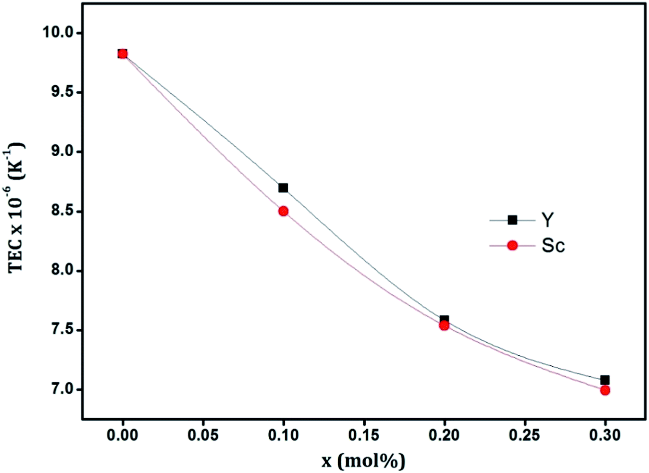 | ||
| Fig. 7 Variation of thermal expansion coefficient (TEC) with substitution. | ||
Morphology
The powder X-ray diffraction pattern serves to indicate only the average crystalline nature of a bulk sample and hence transmission electron microscopy (TEM) was used to confirm the crystallinity of the chemical systems in small domains. HR-TEM images of some representative samples are given in ESI (Fig. S3†).The surface morphology of sintered pellets were examined using scanning electron microcopy. The SEM images of polished surfaces of two representative samples are shown in Fig. 8. The typical polycrystalline morphology consisted of grains varying in size, generally in 2 μm to 6 μm range. Distinct grain boundaries could be seen along with some amount of porosity.
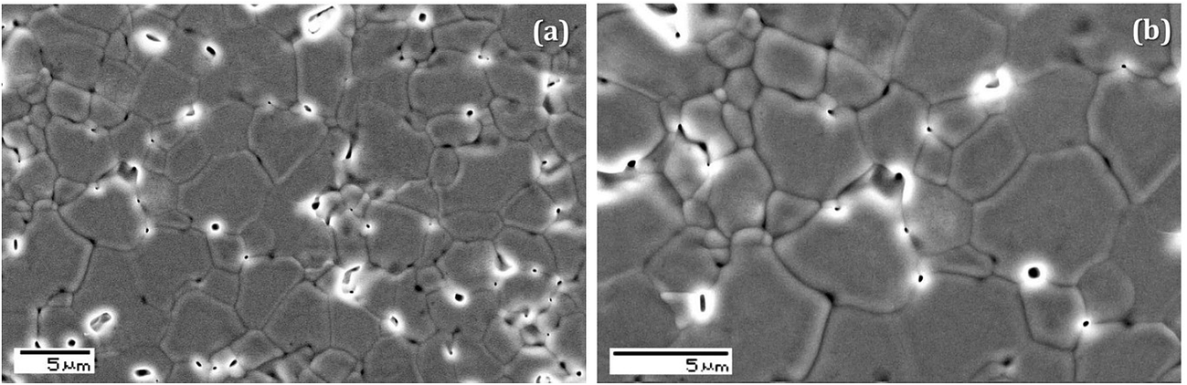 | ||
| Fig. 8 SEM images of the polished surfaces of two representative samples (a) GZY3 (b) GZS3. | ||
Electrical behavior
The sintered pellets of the prepared samples were given a small ac signal (100 mV) of varying frequency (1 Hz to 1 MHz) and their response was analyzed using impedance spectroscopic technique. The measurements were made on heating conditions, from 473 K to 1023 K. A polycrystalline material in such a scenario is often considered a series of parallel RC-circuits, with the resistor (R) corresponding to conduction and the capacitor (C) corresponding to the charge accumulation effects. A Nyquist plot of imaginary part of impedance against the real part of an RC parallel circuit is a semicircle with radius R. Since the capacitance values associated with charge accumulation depends on where it happens, whether it is within the bulk of grains, in the grain boundaries or in the sample–electrode interface, the Nyquist plot for a polycrystalline material will ideally consist of three semicircular arcs.Fig. 9 shows this complex plane representation of ac impedance of a representative sample, GZY3, at two different temperatures. Two semicircles could be distinguished, the mechanisms responsible for which can be identified from the capacitance values associated with them. Grain boundaries offer higher capacitance due to bigger chances of charge polarization and therefore the relaxation associated with the grain boundary phenomena falls in lower frequency region, whereas the grain relaxation happens in higher frequencies.44 Depending on the range of measurement frequency and the difference in relaxation frequencies between grain and grain boundary phenomena, the semicircles may appear incomplete or merged as observed in Fig. 9. The intercept of an impedance semicircle with the real axis gives the ohmic resistance, R, offered against the conduction process associated with it. With increase in temperature, the semicircles diminish in radius indicating a decrease in resistance. Considering the sample thickness (l) and the electroding area (A), the conductivity σ can be calculated as
| σ = l/RA | (2) |
 | ||
| Fig. 9 Complex plane representation of ac impedance of representative sample, GZY3, at two temperatures. | ||
Since the grain and grain boundary semicircles were not always well-resolved, only their total resistance was considered to calculate the conductivity at various temperatures. The conductivity value increases with increase in temperature. This dependence is generally described by the Arrhenius equation,
| σ = (σ0/T)exp(−Ea/kBT) | (3) |
Fig. 10 shows the Arrhenius plots of various samples, where the straight lines are the least squares fit of the conductivity data with the linearized form of eqn (3). The slopes of the straight line fits would yield the values of activation energy. The values of conductivity at maximum measuring temperature (1023 K) and the activation energy of various samples are shown in Fig. 11.
 | ||
| Fig. 10 Arrhenius plots of various samples (a) GZY series (b) GZS series. | ||
 | ||
| Fig. 11 Effect of substitution on (a) conductivity and (b) activation energy of various samples. | ||
It can be seen that, for GZY series, the conductivity increases with increase in substitution along with a corresponding decrease in activation energy. But in the case of GZS series, the trend is different. With substitution of Sc3+, the activation energy decreases at first and then it starts to increase which reflects directly in the trend of conductivity variation also.
For a better understanding of the processes involved, analysis was extended to electric modulus function, M*, which is essentially the reciprocal of dielectric permittivity and is connected to complex impedance (Z*) as,45
| M* = jωC0Z* | (4) |
Fig. 12 shows a frequency plot of the imaginary part (M′′) of the electric modulus at various temperatures measured on the representative sample GZY3. Its value is nearly zero in the low frequency region for all temperatures, but shows a peak at a particular frequency which shifts towards higher values with increase in temperature.
 | ||
| Fig. 12 Frequency plot of imaginary part of electric modulus of representative sample GZY3. | ||
The peak is obviously an indication of the dielectric relaxation behavior which in oxide ionic conductors is often attributed to the charge re-orientation of ions involving the vacancies.46,47 The low-frequency side of the relaxation peak corresponds to long-range conduction of ions whereas the higher frequency side to spatially confined ions.48 The peak-shift to higher frequency implies a thermally activated ionic transport to which Arrhenius fitting is possible and activation energy could be calculated from that. The activation energies calculated from modulus and conductivity considerations were similar in values which indicated that the conduction mechanism in these materials is primarily through ion hopping.48,49
The trend in conductivity as observed in Fig. 11 can now be explained in terms of the oxygen vacancies and the lattice disorder. The reason for enhanced conductivity in GZY series with substitution of Y3+ is apparently obvious. It has already been noted that both the cation substitutions are inducing a disorder to the lattice, driving the radius ratio (rA/rB) from 1.46 for Gd2Zr2O7 towards 1, the value for ideal fluorite structure. This is in effect necessitating an increase in average coordination number of the cations. Y3+ being larger in radius compared to Sc3+ will be able to cooperate with this more, since it will have a larger surface area to afford the increased coordination number. Although oxygen vacancies are formed by both aliovalent substitutions, Y-substituted compositions will be able to facilitate a lower energy pathway for ionic transport within the crystal due to ease of coordination and increase in lattice volume. However, the effect of Sc3+ substitution in GZS series is different. Although the activation energy decreases at first due to increase in available oxygen vacancies, the system fails to keep that up for higher substituent concentration.
It may be due to the cooperative behavior of ions in the lattice as conceived by Jonscher50 where hopping of one ion can cause a time-dependent movement of other charge carriers in the neighborhood leading to additional relaxations. This would lead to a broadening of relaxation peaks in the modulus spectra51,52 as can be seen in Fig. 13, which shows a plot of imaginary part of electric modulus (normalized by maximum, M′′/M′′max) of various GZS samples at 523 K. Various plots were shifted along the abscissa for clarity and beyond x = 0.1, a broadening of peak can be observed indicating a correlated ionic motion. This ion–ion interaction is generally reported to be detrimental to the overall electrical conductivity by posing a higher activation energy for long range ionic transport.53 This increased cooperative behavior of oxygen vacancies in Sc-substituted compositions may be a result of the negative chemical expansion. Thus it comes out that, although Sc and Y belong to the same group, their influences on the overall behavior of the parent lattice are different from one another.
 | ||
| Fig. 13 Broadening of modulus relaxation peak of GZS samples at 523 K (plots were shifted along the abscissa for clarity). | ||
Conclusion
Gd2(Zr1−xMx)2O7−δ solid solutions were prepared to investigate the effect of substitution by M cation (M = Sc3+, Y3+) on structure and electrical properties. Both systems crystallized in fluorite-type lattice, showing similar extent of solid solution formation. Sc3+ lead to a contraction of the lattice via lattice defects, while Y3+ forced the lattice to expand due to its larger ionic radius. Both systems had oxygen vacancies due to aliovalent substitution, but their effect was more pronounced in the Sc-substituted compositions, as was evident in X-ray diffraction and Raman analysis. Oxygen vacancies in the expanded lattice aided in enhanced electrical properties in Y-substituted system by reducing the energy barrier for thermally activated conduction. Whereas for Sc-substituted system, cooperative behavior of ions in the contracted lattice acted in the reverse direction. Thus it could be concluded that, despite them being in the same group of d-block elements, the ultimate influence in physical aspects depended on the identity of the substituent ions.Acknowledgements
One of the authors, Vaisakhan Thampi, wishes to acknowledge University Grants Commission (UGC-India) for financial assistance.References
- L. Carrette, K. A. Friedrich and U. Stimming, Fuel Cells, 2001, 1, 5–39 CrossRef CAS.
- S. P. S. Badwal and K. Foger, Ceram. Int., 1996, 22, 257–265 CrossRef CAS.
- F. M. L. Figueiredo and F. M. B. Marques, Wiley Interdiscip. Rev.: Energy Environ., 2013, 2, 52–72 CrossRef CAS PubMed.
- S. P. S. Badwal and F. T. Ciacchi, Ionics, 2000, 6, 1–21 CrossRef CAS.
- K. V. G. Kutty, C. K. Mathews, T. N. Rao and U. V. Varadaraju, Solid State Ionics, 1995, 80, 99–110 CrossRef.
- P. J. Wilde and C. R. A. Catlow, Solid State Ionics, 1998, 112, 173–183 CrossRef CAS.
- M. Pirzada, R. W. Grimes, L. Minervini, J. F. Maguire and K. E. Sickafus, Solid State Ionics, 2001, 140, 201–208 CrossRef CAS.
- M. P. van Dijk, A. J. Burggraaf, A. N. Cormack and C. R. A. Catlow, Solid State Ionics, 1985, 17, 159–167 CrossRef CAS.
- A. J. Burggraaf, T. van Dijk and M. J. Verkerk, Solid State Ionics, 1981, 5, 519–522 CrossRef CAS.
- K. Shimamura, T. Arima, K. Idemitsu and Y. Inagaki, Int. J. Thermophys., 2007, 28, 1074–1084 CrossRef CAS.
- M. A. Subramanian, G. Aravamudan and G. V. Subba Rao, Prog. Solid State Chem., 1983, 15, 55–173 CrossRef CAS.
- A. N. Radhakrishnan, P. P. Rao, K. S. M. Linsa, M. Deepa and P. Koshy, Dalton Trans., 2011, 40, 3839–3848 RSC.
- D. S. Vaisakhan Thampi, P. Prabhakar Rao and A. N. Radhakrishnan, RSC Adv., 2014, 4, 12321–12329 RSC.
- Z.-G. Liu, J.-H. Ouyang, Y. Zhou and X.-L. Xia, Mater. Des., 2009, 30, 3784–3788 CrossRef CAS PubMed.
- X.-L. Xia, Z.-G. Liu, J.-H. Ouyang, S. Gao and X.-M. Liu, Solid State Sci., 2011, 13, 1328–1333 CrossRef CAS PubMed.
- X.-L. Xia, J.-H. Ouyang and Z.-G. Liu, J. Am. Ceram. Soc., 2010, 93, 1074–1080 CrossRef CAS PubMed.
- Y. H. Lee, H. S. Sheu, J. P. Deng and H. C. I. Kao, J. Alloys Compd., 2009, 487, 595–598 CrossRef CAS PubMed.
- L. Zhan-Guo, O. Jia-Hu, Z. Yu and X. Xiao-Liang, Ceram. Int., 2009, 35, 2387–2392 CrossRef PubMed.
- Z.-G. Liu, J.-H. Ouyang, Y. Zhou and X.-L. Xia, J. Power Sources, 2008, 185, 876–880 CrossRef CAS PubMed.
- Z.-G. Liu, S. Gao, J.-H. Ouyang and X.-L. Xia, J. Alloys Compd., 2010, 506, 868–871 CrossRef CAS PubMed.
- Z.-G. Liu, J.-H. Ouyang, K.-N. Sun and Y. Zhou, Ceram. Int., 2012, 38, 2935–2941 CrossRef CAS PubMed.
- X.-L. Xia, S. Gao, Z.-G. Liu and J.-H. Ouyang, Electrochim. Acta, 2010, 55, 5301–5306 CrossRef CAS PubMed.
- T. Degen, M. Sadki, E. Bron, U. König and G. Nénert, Powder Diffr., 2014, 29, S13–S18 CrossRef CAS.
- L. Vegard, Z. Phys., 1921, 5, 17–26 CrossRef CAS.
- R. Shannon, Acta Crystallogr., Sect. A: Cryst. Phys., Diffr., Theor. Gen. Crystallogr., 1976, 32, 751–767 CrossRef.
- D. Marrocchelli, S. R. Bishop and J. Kilner, J. Mater. Chem. A, 2013, 1, 7673–7680 CAS.
- C. Chatzichristodoulou, P. Norby, P. Hendriksen and M. Mogensen, J. Electroceram., 2015, 34, 100–107 CrossRef CAS.
- F. N. Sayed, B. P. Mandal, D. Jain, C. G. N. S. Pillai and A. K. Tyagi, J. Eur. Ceram. Soc., 2012, 32, 3221–3228 CrossRef CAS PubMed.
- V. Thampi, P. R. Padala and A. N. Radhakrishnan, New J. Chem., 2015, 39, 1469–1476 RSC.
- R. W. B. N. Kjerulf-Jensen and F. W. Poulsen, 2nd European Solid oxide fuel cell forum, 1996 Search PubMed.
- A. Banerji, V. Grover, V. Sathe, S. K. Deb and A. K. Tyagi, Solid State Commun., 2009, 149, 1689–1692 CrossRef CAS PubMed.
- J. R. McBride, K. C. Hass, B. D. Poindexter and W. H. Weber, J. Appl. Phys., 1994, 76, 2435–2441 CrossRef CAS PubMed.
- L. Li, F. Chen, J.-Q. Lu and M.-F. Luo, J. Phys. Chem. A, 2011, 115, 7972–7977 CrossRef CAS PubMed.
- B. P. Mandal, A. Banerji, V. Sathe, S. K. Deb and A. K. Tyagi, J. Solid State Chem., 2007, 180, 2643–2648 CrossRef CAS PubMed.
- C. Wan, Z. Qu, A. Du and W. Pan, J. Am. Ceram. Soc., 2011, 94, 592–596 CrossRef CAS PubMed.
- T. Moriga, S. Emura, A. Yoshiasa, S. Kikkawa, F. Kanamaru and K. Koto, Solid State Ionics, 1990, 40–41, 357–361 CrossRef CAS , Part 1.
- N. J. Hess, B. D. Begg, S. D. Conradson, D. E. McCready, P. L. Gassman and W. J. Weber, J. Phys. Chem. B, 2002, 106, 4663–4677 CrossRef CAS.
- B. C. Chakoumakos, J. Solid State Chem., 1984, 53, 120–129 CrossRef CAS.
- L. Minervini, R. W. Grimes and K. E. Sickafus, J. Am. Ceram. Soc., 2000, 83, 1873–1878 CrossRef CAS PubMed.
- C. Kim, A. Mehta, D. L. Feng, K. M. Shen, N. P. Armitage, K. Char, S. H. Moon, Y. Y. Xie and J. Wu, Phys. Rev. B: Condens. Matter Mater. Phys., 2003, 67, 092508 CrossRef.
- S. K. Mohanlal, J. Phys. C: Solid State Phys., 1979, 12, L651–L653 CrossRef CAS PubMed.
- CRC Handbook of Chemistry and Physics, ed. D. R. Lide, 2005 Search PubMed.
- A. D. Arulsamy, Ann. Phys., 2011, 326, 541–565 Search PubMed.
- Z. G. Liu, J. H. Ouyang and K. N. Sun, Fuel Cells, 2010, 10, 1050–1056 CrossRef CAS PubMed.
- I. M. Hodge, M. D. Ingram and A. R. West, J. Electroanal. Chem., 1976, 74, 125–143 CrossRef CAS.
- P. Sarkar and P. S. Nicholson, J. Am. Ceram. Soc., 1989, 72, 1447–1449 CrossRef CAS PubMed.
- A. K. Baral and V. Sankaranarayanan, Appl. Phys. Lett., 2009, 94, 074101 CrossRef PubMed.
- J. M. Réau, S. Rossignol, B. Tanguy, J. M. Rojo, P. Herrero, R. M. Rojas and J. Sanz, Solid State Ionics, 1994, 74, 65–73 CrossRef.
- K. P. Padmasree, D. K. Kanchan and A. R. Kulkarni, Solid State Ionics, 2006, 177, 475–482 CrossRef CAS PubMed.
- A. K. Jonscher, Nature, 1977, 267, 673–679 CrossRef CAS PubMed.
- J. García-Barriocanal, K. J. Moreno, G. Mendoza-Suárez, A. F. Fuentes, J. Santamaría and C. León, J. Non-Cryst. Solids, 2005, 351, 2813–2818 CrossRef PubMed.
- K. Moreno, G. Mendoza-Suárez, A. Fuentes, J. García-Barriocanal and C. L. J. Santamaria, Phys. Rev. B: Condens. Matter Mater. Phys., 2005, 71, 132301 CrossRef.
- J. Garcia-Barriocanal, A. Rivera-Calzada, M. Varela, Z. Sefrioui, M. R. Díaz-Guillén, K. J. Moreno, J. A. Díaz-Guillén, E. Iborra, A. F. Fuentes, S. J. Pennycook, C. Leon and J. Santamaria, ChemPhysChem, 2009, 10, 1003–1011 CrossRef CAS PubMed.
Footnote |
| † Electronic supplementary information (ESI) available. See DOI: 10.1039/c5ra17203a |
| This journal is © The Royal Society of Chemistry 2015 |