Self-directedly assembled porphyrin thin films with high photoactivity
Bing Yuana,
Riyue Gea,
Shi-Zhao Kanga,
Lixia Qina,
Guodong Lib and
Xiangqing Li*a
aSchool of Chemical and Environmental Engineering, Shanghai Institute of Technology, 100 Haiquan Road, Shanghai 201418, China. E-mail: xqli@sit.edu.cn; Fax: +86 21 64253317; Tel: +86 21 60873061
bState Key Laboratory of Inorganic Synthesis Preparative Chemistry, College of Chemistry, Jilin University, Changchun 130012, China
First published on 23rd October 2015
Abstract
A novel silanized metalloporphyrin cobalt monomer (SMPCM) was prepared by using 5,10,15,20-tetra(4-hydroxyphenyl)porphyrin cobalt (CoTHPP) and γ-isocyanatopropyltriethoxysilane (ICPTES) as the reactants. Followed by the hydrolysis–polymerization of the organosilanes in the axial direction and peripheries of the SMPCM, the ordered porphyrin thin films with uniform morphology were facilely prepared on various substrates by the self-directed assembly of the SMPCM. The thin films formed was characterized by UV-vis spectra, electron microscopies, X-ray diffraction spectra, Fourier transform infrared spectra, fluorescence spectra and X-ray photoelectron spectra. The results demonstrated that the axial assembly between the Co3+ ion in the center of porphyrin macrocycle and ICPTES can prevent porphyrin lamellar from curling in horizontal direction, and then enhanced the order and stability of the films. Especially, the thin films possessed high, sensitive and stable photoelectronic response.
1. Introduction
The already sizable field of thin films continues to expand at a remarkable pace in the last two decades because of their vital applications in nonlinear optical materials, light-harvesting, and hierarchical assembly of ordered chromophores.1–5 Porphyrins and their derivatives possess important electronic features such as high molar absorption coefficients, rich redox chemistry and fast photoinduced energy/electron transfer abilities, and are excellent chromophore candidates in thin films.6,7 In addition, the properties can be modified by changing peripheral substituents and/or central metal ions of porphyrins, which are important factors to control the growth orientation and thickness of thin films.The well-ordered porphyrin thin films are prepared quickly, which is of great importance in the production of electronic and optical materials and devices. Nowadays, a number of methods have been developed to assemble ordered thin films. Hermes and co-workers fabricate metal–organic open framework thin films using solvothermal technique.8 Though solvothermal method is applied in many reports afterwards, it needs longer time. Hupp et al. synthesized two kinds of porphyrin-based thin films on the functionalized substrates using a layer-by-layer approach for light-harvesting and ultrafast long-distance energy.9 The building blocks used are porphyrin bases, bridged molecules and metal ions. A distinct advantage of this method is that it can control the growth orientation in the vertical direction to the substrate and layer numbers of the films. However, the order of the thin film in the horizontal direction is hard to be controlled, although the periodic structure sometimes occurs as a consequence of van der Waals or π–π interactions.10 In addition, long time and well-trained technicians are also needed. Langmuir–Blodgett technique is a good way to fabricate highly-oriented monofilm on the liquid surface, and the film can be easily transferred onto the solid substrate. In this process, the Langmuir groove is integrant, and the condition is also rigorous. So a facile and cheap method used to prepare the functional porphyrin thin films is urgently needed.
Peng and coworkers have demonstrated a novel synthesis of two-dimensional porphyrin/silica nanocomposite films through the self-direct assembly of bridged silsesquioxane.11 Using an evaporation-induced self-assembly process, Li et al. prepared a photoactive porphyrin-based periodic mesoporous organosilica thin film with a tetra-substituted porphyrin silsesquioxane as a precursor.12 It is also found that photo-induced charge transfer in zinc phthalocyanine based periodic mesoporous organosilica can be promoted by being impregnated with a fullerene derivative.13 These researches provide an efficient way to prepare thin films based on the hydrolysis–polymerization of the organosilane. Unfortunately, the efficiency of electron transfer in thin films was low due to the unsatisfactory structure of thin films.
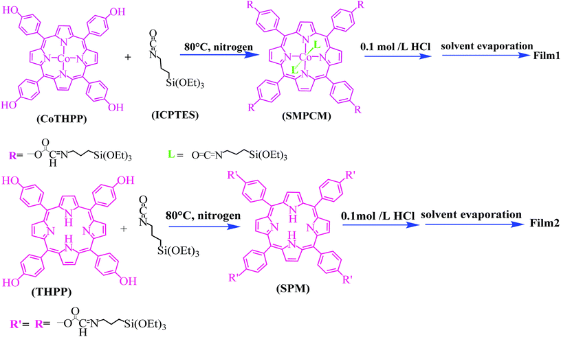
Herein, a silanized metalloporphyrin cobalt monomer (SMPCM) is first synthesized by using 5,10,15,20-tetra (4-hydroxyphenyl) porphyrin cobalt (CoTHPP) and γ-isocyanatopropyltriethoxysilane (ICPTES) as the reactants. A novel metalloporphyrin-based thin films are prepared through the self-directed assembly of the SMPCM precursor. Furthermore, the photoelectronic response and thermal stability of thin films are investigated.
2. Experimental section
2.1 Materials
5,10,15,20-Tetrahydroxylphenylporphyrin (THPP) was purchased from J&K Scientific Ltd. Cobalt(II) acetate anhydrous, triethanolamine (TEA), N,N-dimethylformamide (DMF), tetrahydrofuran (THF) and ICPTES were purchased from Sinopharm Chemical Co., Ltd. All reagents were analytical grade and were used without further purification. Double-distilled water was used for all the experiments. THF was pre-treated by refluxing THF solution containing Na/benzophenone. TEA was also pre-treated by refluxing TEA solution containing calcium hydride.2.2 Synthetic procedures
Next, HCl (0.08 mL, 0.1 mol L−1) was added into the SMPCM THF solution, and the mixture was stirred at room temperature for 4 h. The resulting solution (Solution 1) was casted onto a substrate, and the film 1 was achieved after solvent evaporation.
Next, HCl (0.08 mL, 0.1 mol L−1) was added into the SPM THF solution, and the mixture was stirred at room temperature for 4 h. The resulting solution (Solution 2) was casted onto a substrate, and the film 2 was achieved after solvent evaporation.
2.3 Characterizations
UV-vis absorption spectra were recorded with a UV-3900 spectrophotometer (Japan). High resolution transmission electron microscope (TEM) images were taken with a JEOLJEM-2100 transmission electron microscope (Japan). Field emission scanning electron microscope (FE-SEM) measurements were performed on a NOVA Nano SEM450 (USA). Atomic force microscopy (AFM) image was obtained by Nanonavi E-Sweep atomic force microscopy with tapping mode (Japan). The X-ray diffraction patterns (XRD) were collected on a Bruker D8 ADVANCE X-ray diffractometer and operated at 40 kV and 40 mA with Cu-Kα radiation (λ = 0.154 nm). Scanning region was in range of 2θ = 0.5–6°, and the scanning rate was 0.1° min−1 (Germany). Fourier transform infrared spectra (FTIR) were recorded at room temperature on a Nicolet 6700 FTIR spectrometer (USA). Fluorescence spectra were measured using an F-4600 fluorescence spectrophotometer (Japan). X-ray photoelectron spectrum (XPS) measurements were made on Thermo Fisher ESCALAB 250Xi, and equipped with a monochromatic X-ray source (Al Kα hν = 1486.6 eV), using C 1s (285.0 eV) as a reference to correct the binding energy (USA). Thermogravimetric analyses (TGA) were carried out on a WRT-2 Thermo-Gravimetric Analyzer (China). All samples were heated at a scanning rate of 10 °C min−1 under nitrogen atmosphere. Electrochemical measurements were performed on a CHI 660E electrochemical workstation (China).2.4 Preparation of working electrodes and photoelectrochemical behavior measurement
Fluorine-doped tin oxide (FTO) glass coated the film was used as the working electrode. It was prepared as the following procedure. The FTO glass was firstly cleaned by sonication in ethanol, acetone, chloroform and deionized water for 10 min, respectively, and then dried in air. The working electrodes were prepared by immersing the cleaned FTO glasses into the Solution 1 or the Solution 2. After 30 min, the FTO glass was lifted out and washed with ultrapure water, and then dried.The photocurrent measurements were carried out in 0.2 mol L−1 NaH2PO4 and 0.2 mol L−1 Na2HPO4 (PBS, pH = 7.4) aqueous solution by using a three-electrode system. The FTO glass assembled with the film 1 or film 2 acted as the working electrode. A Pt wire was used as the counter electrode and a saturated calomel electrode as the reference electrode. The light source was a 150 W xenon lamp (λ = 200–1800 nm). The area of light irradiation was 1 cm2. The bias voltage was controlled at −50 mV. All experiments were carried out at about 25 °C.
3. Results and discussion
3.1 Morphology and composition of the films
The surface morphologies of the films were observed by the FE-SEM. As shown in Fig. 1a and b, the morphologies of the film 1 and the film 2 are different. In the film 2, some separated and partly crosslinking particles are observed (Fig. 1a). However, separated particles cannot be observed in the film 1, and a crosslinking and lamellar multilayer films are obtained (Fig. 1b). The porous shown in FE-SEM image could be caused by random hydrolysis–polymerization of some silsesquioxane groups, and it is not real porous (it can not be measured using N2 adsorption or BET measurement). Furthermore, the lamellar morphology of the film 1 can also be observed in its TEM image (Fig. 1c). It is deduced that axial coordination between Co3+ ion in the center of porphyrin macrocycle and ICPTES can prevent the porphyrin lamellar from curling in horizontal direction, which will be further demonstrated by the results in Fig. 3 and 7.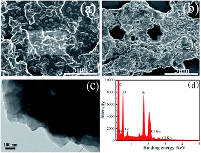 | ||
| Fig. 1 FE-SEM images of the as-synthesized film 2 (a) and film 1 (b); TEM image (c) and EDS spectrum (d) of the as-synthesized film 1. | ||
The signals of C, O, N, Si and Co elements can be observed in the EDX spectrum of the film 1 (Fig. 1d). The C, O and N elements come from the SMPCM and ICPTES; Co comes from SMPCM; and Si element corresponds to the ICPTES. The occurrence of C, O, N, Si and Co signals preliminarily confirms the presence of the SMPCM and ICPTES in the film. AFM image provides more information about the surface of the film 1. As shown in Fig. 2, the film 1 is well-organized, and the surface of the film is uniform.
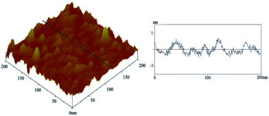 | ||
| Fig. 2 AFM topographic image of the film 1 on the silicon (100) slice (left) and depth profile (right) along the line in the left image. | ||
3.2 Formation and structure of the film
SMPCM solution and SPM solution are the precursor solutions of the film 1 and film 2, respectively. The self-directed assembly of the film 1 was preliminarily confirmed by UV-vis absorption spectra. It can be seen from Fig. 3, the SMPCM solution displays a strong Soret band at 428 nm and two weaker Q bands at 546 nm and 588 nm, respectively. For the film 1, the Soret band is slightly split and broadened, and the absorption intensity is decreased. The split Soret band is located at 418 nm and 439 nm, respectively. However, replacing SMPCM by SPM, the Soret band of the obtained film (film 2) is not split but red-shifted, and the intensity decreases compared with that of the SPM solution (Fig. 3c). It is similar to two-dimensional porphyrin films by self-directed assembly of organosilane reported by Peng et al.11 According to the results in Fig. 3 and those of the literatures reported,12,13 it is deduced that axial coordination between the Co3+ ion in the center of CoTHPP macrocycle and ICPTES has happened besides peripheral reaction between –OH and ICPTES, which causes energy level shifts by the π–π interaction among porphyrin stacking.6,17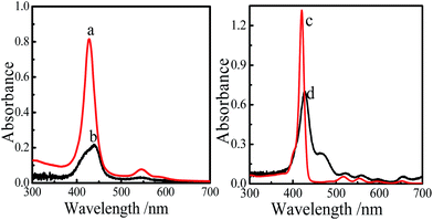 | ||
| Fig. 3 UV-vis absorption spectra of the SMPCM THF solution (a), film 1 (b), SPM THF solution (c) and film 2 (d). | ||
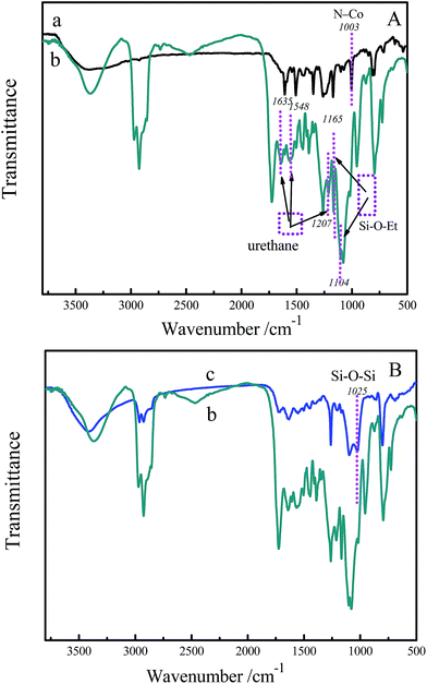
In order to further demonstrate the formation of SMPCM and film 1, the FTIR spectra of the CoTHPP, SMPCM and film 1 were measured. As can be seen in Fig. 4a, the broad band at 3383 cm−1 can be assigned to the stretching vibration of the –OH groups in hydrogen bond. However, the band is red-shifted to 3373 cm−1 and becomes narrow (Fig. 4b), which indicates that the reaction has occurred between the hydroxyl groups and isocyanate groups.18 The strong absorption at 1094 cm−1 together with a weak absorption at 1165 cm−1 correspond to Si–O–C vibration. The absorption band at 1261 cm−1 is attributed to the Si–C stretching vibration. The appearance of these bands indicates the presence of the ICPTES in the film 1.19 Moreover, the stretching vibrations corresponding to urethane groups can be observed at 1635 cm−1, 1548 cm−1 and 1207 cm−1, which indicates the formation of urethane linkages.20 In Fig. 4c, the Si–O–Si vibration band at 1025 cm−1 is an evidence for the hydrolysis–polymerization of silsesquioxanes linked on the CoTHPP macrocycle.21 In addition, the vibration of Co–N is located at about 1003 cm−1 for the CoTHPP (Fig. 4a). However, the vibration is blue-shifted 24 cm−1 after reacting with ICPTES, which indicates the axial coordination of central metal ions of porphyrin macrocycles and ICPTES.22,23 The blue shift of M − N vibration band demonstrates that the symmetry of the film and interaction between porphyrin macrocycles are enhanced because of the axial coordination.24,25
The comparative fluorescence spectra of SMPCM, film 1 and film 2 are recorded to examine the photo-induced electron transfer in the samples. As shown in Fig. 5a, there exist a strong emission peak at 659 nm and a weak one at 725 nm for the film 2, which corresponds to the fluorescence peaks of the porphyrin. However, the fluorescence are quenched in the film 1 and SMPCM, indicating the occurrence of photo-induced electron or energy transfer in the film 1 and SMPCM.26 It is found that, at the same condition, the fluorescence of the film 1 was lower than that of the SMPCM. It could be caused by axial linkage between SMPCM through coordination and hydrolysis–polymerization of ICPTES, and more oriented structure for the film 1.27,28
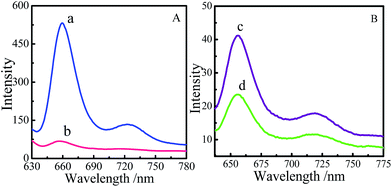 | ||
| Fig. 5 Fluorescence spectra of the film 2 (a) and the film 1 (b); fluorescence spectra of SMPCM (c) and film 1 (d). λex = 415 nm. | ||
X-ray photoelectron spectrum (XPS) is used to obtain the information about element composition and the binding state of N atoms in the film 1. In Fig. 6a, the peaks of C, O, N, Si and Co elements are clearly observed, which is consistent with the result of EDX (Fig. 1d). Furthermore, the high-resolution XPS spectrum of N1s for the film 1 is examined. The deconvoluted XPS spectrum of N1s is displayed in Fig. 6b. Three components of nitrogen-based atoms are observed in the film 1: the N1s peak is dominated by pyrrolic N at 400.06 eV. One weak peak at 401 eV is assigned to the coordinated nitrogen in the ICPTES, and another peak at 398.8 eV is attributed to peripheral nitrogen species in the SMPCM.29–32 According to the literature,33 the two shake-up satellite peaks at 787.9 eV and 803.6 eV should be able to be observed for Co2+. But they did not appeared in the high resolution XPS of Co2p (Fig. 6c). It is indicated that there does not exist Co2+ in the film. While the peaks at 795.3 eV and 780.3 eV in Fig. 6c confirm the presence of Co3+ in the film.33 Therefore, the cobalt sites in the porphyrin are Co(III).
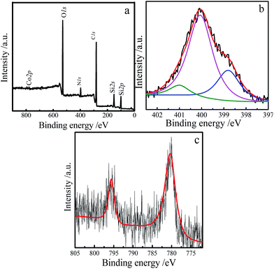 | ||
| Fig. 6 XPS survey spectrum of the film 1 (a), high resolution XPS spectrum of the N1s (b) and Co2p (c). | ||
The result of XPS further demonstrates that the film 1 is achieved by the hydrolysis–polymerization of silsesquioxanes linking on the peripheries and axial direction of the SMPCM.
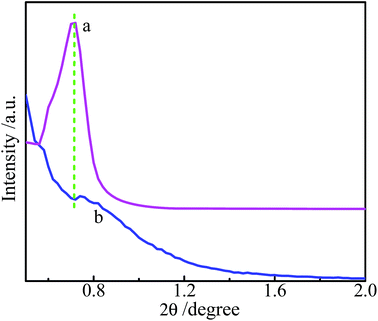
Small-angel XRD was used to characterize the structure of the films. As shown in Fig. 7, the as-prepared film 1 exhibits a stronger and wider diffraction peak at 2θ = 0.7°. It indicates that a layered and highly oriented film has been developed,12,34 and the d-space is about 12.6 nm along the normal direction of the film. While the as-prepared film 2 exhibits a very weak peak at 2θ = 0.75°, corresponding to d-space of 11.8 nm. The larger d-space in the film 1 could be due to the coordination of ICPTES with the Co3+ in the center of the porphyrin macrocycle and the followed hydrolysis–polymerization of silsesquioxanes in axial direction.
As evidenced by FTIR, the ligands (ICPTES) coordinate with Co(III) and bridge to form the connection axially, and then the silsesquioxane groups linking on the peripheries and axial directions of porphyrin macrocycle hydrolysis–polymerize after introducing hydrochloric acid. In addition, the split, broadened Soret and one weak N1s peak at 401 eV assigned to the coordinated nitrogen, also indicate that axial coordination between the Co3+ ion in the center of CoTHPP macrocycle and ICPTES is formed by Co–N linkage because of the lower electronegativity of N atom.35
O![[double bond, length as m-dash]](https://www.rsc.org/images/entities/char_e001.gif) C
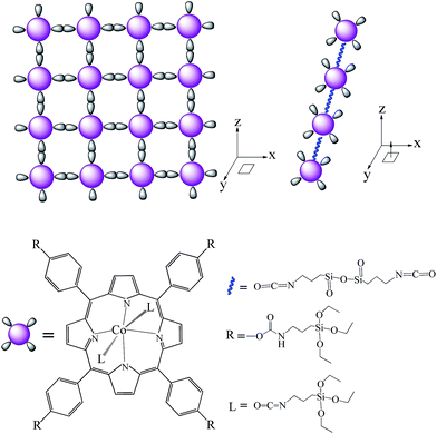
C![[double bond, length as m-dash]](https://www.rsc.org/images/entities/char_e001.gif) N– group was contained in the isocyanatopropyltriethoxysilane molecule. Therefore, in the reaction, lone pair electrons in O atom or N atom can be transferred towards the unoccupied orbitals of central Co(III) in the porphyrin macrocycle according to the coordination theory. Referenced to the literature,36 TEM and SEM images, and the coordination theory (the metal ions with higher oxidation state are inclined to six coordinate), it is deduced that the metal sites (Co3+) are six coordinate.
N– group was contained in the isocyanatopropyltriethoxysilane molecule. Therefore, in the reaction, lone pair electrons in O atom or N atom can be transferred towards the unoccupied orbitals of central Co(III) in the porphyrin macrocycle according to the coordination theory. Referenced to the literature,36 TEM and SEM images, and the coordination theory (the metal ions with higher oxidation state are inclined to six coordinate), it is deduced that the metal sites (Co3+) are six coordinate.
Combined with the above results, it is demonstrated that the porphyrin monomer (SMPCM) can self-directedly assembled in 3D directions, just like that shown in Scheme 2. In the process, the SMPCM self-directedly assembles by the hydrolysis–polymerization of the silsesquioxanes linked on its peripheries and axial direction. Consequently, the porphyrin composite thin films can be achieved quickly on various substrates by the simple process.
3.3 Properties of the films
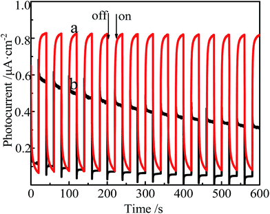
The photoelectronic responses of the films assembled on FTO glasses are detected.As displayed in Fig. 8, the time course of the photocurrent response is observed. The switching interval is ca. 20 s. When the light was turned off, the current was the dark current. The dark current for the film 1 was almost same as that for the film 2 (0.1 μA cm−2). The current increases after turning on the light. When the light is turned off, the current shifts back to the initial level. It is indicated that the film 1 and the film 2 are photosensitive and photoactive. Differently, when the light is turned on, the current for the film 1 is two times higher than that of the film 2. Moreover, the response for the film 1 is faster, and photocurrent response is not attenuated after switching for 600 s. The result demonstrates that the axial coordination between ICPTES and Co3+ in the center of the porphyrin macrocycle is vital to improve photoelectronic performance of the film.
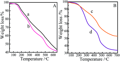
The thermal stability of the samples was studied by thermogravimetric analysis (TGA). As shown in Fig. 9, both films show gradual weight loss starting from 206 °C to 600 °C. The weight loss at about 200 °C is assigned to decomposition and condensation of the residual hydroxyl groups in the film. The weight loss at about 400 °C is assigned to decomposition of porphyrin ring in the film.37,38 In the range of 200–400 °C, the weight loss of the film 1 is lower than that of the film 2, and film 1 and film 2 show 44% and 64% weight loss at 600 °C, respectively. As can be seen in Fig. 9A, the thermal stability of SMPCM is similar to that of the SPM. It is concluded that, the hydrolysis–polymerization of the organosilanes in horizontal direction and axial direction of the SMPCM lead to a more stable three-dimensional porphyrin film (film 1).
4. Conclusions
In conclusion, we have developed a novel porphyrin films by self-directed assembly of the SMPCM. The porphyrin films obtained were ordered and were with uniform morphology. It can be facilely achieved on various substrates. It was found that the axial assembly between the Co3+ ion in the center of porphyrin macrocycle and ICPTES can prevent porphyrin lamellar from curling in horizontal direction, and further enhanced the order and stability of the films. Moreover, the three-dimensional porphyrin films, formed by hydrolysis–polymerization of the organosilanes in the axial direction and peripheries of the SMPCM, possessed high, sensitive and stable photoelectronic response compared with that of the two-dimensional films.Acknowledgements
This work was financially supported by the National Natural Science Foundation of China (Grant No. 21301118, 21305092, 21371070 and 21071060), and Innovation Program of Shanghai Municipal Education Commission (No. 15ZZ096).References
- J. Humphrey and D. Kuciauskas, J. Phys. Chem. B, 2004, 108, 12016–12023 CrossRef CAS.
- L. Jiang, F. Lu, H. Li, Q. Chang, Y. Li, H. Liu, S. Wang, Y. Song, G. Cui, N. Wang, X. He and D. Zhu, J. Phys. Chem. B, 2005, 109, 6311–6315 CrossRef CAS PubMed.
- A. Huijser, T. J. Savenije, A. Kotlewski, S. J. Picken and L. D. A. Siebbeles, Adv. Mater., 2006, 18, 2234–2239 CrossRef CAS.
- J. Rawson, A. C. Stuart, W. You and M. J. Therien, J. Am. Chem. Soc., 2014, 136, 17561–17569 CrossRef CAS PubMed.
- M. Zhu, G. H. Aryal, N. Zhang, H. Zhang, X. Su, R. Schmehl, X. Liu, J. Hu, J. Wei and J. Jayawickramarajah, Langmuir, 2015, 31, 578–586 CrossRef CAS PubMed.
- C.-L. Wang, C.-M. Lan, S.-H. Hong, Y.-F. Wang, T.-Y. Pan, C.-W. Chang, H.-H. Kuo, M.-Y. Kuo, E. W.-G. Diau and C.-Y. Lin, Energy Environ. Sci., 2012, 5, 6933 CAS.
- G. de la Torre, G. Bottari, M. Sekita, A. Hausmann, D. M. Guldi and T. Torres, Chem. Soc. Rev., 2013, 42, 8049–8105 RSC.
- S. Hermes, F. Schröder, R. Chelmowski, C. Wöll and R. A. Fischer, J. Am. Chem. Soc., 2005, 127, 13744–13745 CrossRef CAS PubMed.
- M. C. So, S. Jin, H. J. Son, G. P. Wiederrecht, O. K. Farha and J. T. Hupp, J. Am. Chem. Soc., 2013, 135, 15698–15701 CrossRef CAS PubMed.
- R. Makiura, S. Motoyama, Y. Umemura, H. Yamanaka, O. Sakata and H. Kitagawa, Nat. Mater., 2010, 9, 565–571 CrossRef CAS PubMed.
- H. Peng and Y. Lu, Adv. Mater., 2008, 20, 797–800 CrossRef CAS.
- Y. Li, F. Auras, F. Lobermann, M. Doblinger, J. Schuster, L. Peter, D. Trauner and T. Bein, J. Am. Chem. Soc., 2013, 135, 18513–18519 CrossRef CAS PubMed.
- F. Auras, Y. Li, F. Lobermann, M. Doblinger, J. Schuster, L. M. Peter, D. Trauner and T. Bein, Chem.–Eur. J., 2014, 20, 14971–14975 CrossRef CAS PubMed.
- J. Wen and G. L. Wilkes, Polym. Bull., 1996, 37, 51–57 CrossRef CAS.
- G. Cerveau, R. J. P. Corriu, F. Lerouge, N. Bellec, D. Lorcy and M. Nobili, Chem. Commun., 2004, 396–397 RSC.
- C. Shen, G. Kong, J. Wang and X. Zhang, Int. J. Hydrogen Energy, 2015, 40, 363–372 CrossRef CAS.
- N. Kanetada, C. Matsumura, S. Yamazaki and K. Adachi, ACS Appl. Mater. Interfaces, 2013, 5, 12991–12999 CAS.
- T. Iwata, A. Watanabe, M. Iseki, M. Watanabe and H. Kandori, J. Phys. Chem. Lett., 2011, 2, 1015–1019 CrossRef CAS.
- E. Poli, V. Chaleix, C. Damia, Z. Hjezi, E. Champion and V. Sol, Anal. Methods, 2014, 6, 9622–9627 RSC.
- S. Tanaka, H. Honzawa and M. Iji, J. Appl. Polym. Sci., 2013, 130, 1578–1587 CrossRef CAS.
- H. Sanaeepur, A. Kargari and B. Nasernejad, RSC Adv., 2014, 4, 63966–63976 RSC.
- T. S. Kurtikyan, V. A. Hayrapetyan, M. M. Mehrabyan and P. C. Ford, Inorg. Chem., 2014, 53, 11948–11959 CrossRef CAS PubMed.
- T. Zhao, X. Jing, J. Wang, D. Wang, G. Li, Q. Huo and Y. Liu, Cryst. Growth Des., 2012, 12, 5456–5461 CAS.
- J. Mrtz, O. Schneider and M. Hanack, Spectrochim. Acta, Part A, 1982, 38, 1265–1273 CrossRef.
- X. Q. Li, X. Q. Wang, J. F. Guo, L. X. Yu and G. F. Liu, Synth. React. Inorg. Met.-Org. Chem., 2001, 31, 1041–1051 CrossRef CAS.
- M. Jahan, Q. Bao and K. P. Loh, J. Am. Chem. Soc., 2012, 134, 6707–6713 CrossRef CAS PubMed.
- S. Jin, H. J. Son, O. K. Farha, G. P. Wiederrecht and J. T. Hupp, J. Am. Chem. Soc., 2013, 135, 955–958 CrossRef CAS PubMed.
- G. D. Sharma, S. A. Siddiqui, A. Nikiforou, G. E. Zervaki, I. Georgakaki, K. Ladomenou and A. G. Coutsolelos, J. Mater. Chem. C, 2015, 3, 6209–6217 RSC.
- M. S. Killian, J. F. Gnichwitz, A. Hirsch, P. Schmuki and J. Kunze, Langmuir, 2010, 26, 3531–3538 CrossRef CAS PubMed.
- H. Tang, H. Yin, J. Wang, N. Yang, D. Wang and Z. Tang, Angew. Chem., Int. Ed., 2013, 52, 5585–5589 CrossRef CAS PubMed.
- L. Jiang, M. Li, L. Lin, Y. Li, X. He and L. Cui, RSC Adv., 2014, 4, 26653 RSC.
- Q. Lin, X. Bu, A. Kong, C. Mao, X. Zhao, F. Bu and P. Feng, J. Am. Chem. Soc., 2015, 137, 2235–2238 CrossRef CAS PubMed.
- L. Fu, Z. M. Liu, Y. Q. Liu, B. X. Han, P. A. Hu, L. C. Cao and D. B. Zhu, Adv. Mater., 2015, 17, 217–221 CrossRef.
- E.-Y. Jeong, M. B. Ansari and S.-E. Park, ACS Catal., 2011, 1, 855–863 CrossRef CAS.
- Y. Li, F. Auras, F. Lobermann, M. Doblinger, J. Schuster, L. Peter, D. Trauner and T. Bein, J. Am. Chem. Soc., 2013, 135, 18513–18519 CrossRef CAS PubMed.
- T. S. Kurtikyan, S. R. Eksuzyan, V. A. Hayrapetyan, G. G. Martirosyan, G. S. Hovhannisyan and J. A. Goodwin, J. Am. Chem. Soc., 2012, 134, 13861–13870 CrossRef CAS PubMed.
- D. Baskaran, J. W. Mays, X. P. Zhang and M. S. Bratcher, J. Am. Chem. Soc., 2005, 127, 6916–6917 CrossRef CAS PubMed.
- S. M. Yoon, J. Lee, J. H. Je, H. C. Choi and M. Yoon, ACS Nano, 2011, 5, 2923 CrossRef CAS PubMed.
| This journal is © The Royal Society of Chemistry 2015 |

