DOI:
10.1039/C5RA16235A
(Paper)
RSC Adv., 2015,
5, 86137-86143
Sulfur impregnated in a mesoporous covalent organic framework for high performance lithium–sulfur batteries†
Received
12th August 2015
, Accepted 29th September 2015
First published on 30th September 2015
Abstract
Undesirable cycling performance has been considered as the main bottleneck that has hindered the practical application of lithium–sulfur (Li–S) batteries, which mainly results from soluble polysulfides shuttling between the anode and the cathode (so-called shuttle effect). To solve this problem effectively, a covalent organic framework (COF), Azo-COF, with a regular pore distribution of 2.6 nm was prepared as the host for sulfur. Such small mesopores can not only confine the sulfur well in the nanopores but also supply Li+ with one-dimension (1D) transmission channels. Benefiting from this concept, even without a LiNO3 additive, the Li–S battery assembly with a S/Azo-COF cathode presented a high stable capacity of 741 mA h g−1 after 100 cycles while delivering a high initial discharge capacity of nearly 1536 mA h g−1 at 0.1C (1C = 1672 mA g−1). Additionally, when the capacity rate (C-rate) was increased to 2C, a high discharge capacity of 770 mA h g−1 can be still achieved after 20 cycles, proving excellent C-rate performance.
Introduction
The widespread use of portable electronics and the desire for utilizing renewable energy sources such as solar, wind and tidal effectively have created great opportunities as well as challenges for the development of next-generation energy storage systems. State-of-the-art rechargeable batteries based on intercalated lithium, only present low typical capacities of less than 250 mA h g−1 by using lithium transition metal oxides as the cathode material,1 which can not meet the increasing demand of power-intensive applications, including long-range electrical vehicles and stationary energy storage.2 Hence, searching for new cathode materials with higher capacity and energy density as a replacement is of great concern. Recently, lithium–sulfur (Li–S) batteries have been proved to possess the potential to offer a superior theoretical specific capacity of 1675 mA h g−1 and energy density of 2500 W h kg−1 on the basis of active sulfur, which are 3–5 times the magnitude of traditional Li ion batteries.3,4 In addition, the active sulfur, one of the most abundant elements in the earth’s crust, is also low cost and environmentally friendly, making Li–S batteries a promising choice to replace Li ion batteries in next-generation storage systems with high energy density.5,6
However, Li–S batteries are still far from conquering the marketplace mainly due, at least in part, to their own drawbacks. Firstly, the specific capacity output of Li–S batteries is limited by poor utilization of the active material caused by the insulation nature of sulfur and lithium sulfide (Li2S).6–8 Moreover, a volumetric expansion of 80% is accompanied by the lithiation of sulfur during discharge, which will give rise to mechanical damage of cathode materials.9,10 The last and most formidable problem is, namely, shuttle effect, which arises from soluble polysulfides (PS) shuttling between the cathode and the anode during cycling.3,11 All of issues mentioned above lead to low capacity, low coulombic efficiency and fast capacity fading.
To tackle these problems, various nanostructural materials, aiming to embed sulfur species into the micro- or mesopores of hosts such as amorphous carbon,3,6,12–15 carbon nanotubes,7,10,16 carbon fibres,17–20 graphene,21–25 conducting polymers,26–29 and metal oxides,30,31 have been reported. Unfortunately, in order to realize regular and suitable porous structures, appropriate templates with accurate sizes as well as inconvenient and multistep synthesis procedures are evitable.10,19 COF, a member of the porous materials’ family, with a regular pore distribution via strong chemical bonding among its organic molecules, has shown the potential to be developed as a sulfur container.32,33 For instance, Guo et al.,32 have confirmed that a porous aromatic framework (PAF) could impede PS diffusion effectively with a well defined pore distribution of 1.6 nm. An 83% capacity content has been achieved after 50 cycles for a Li–S battery assembly with a S/PAF cathode, showing excellent cycling stability. Despite its towering cycling performance, the C-rate performance has been greatly limited by low rate of Li+ transportation through such micropores. For example, when the C-rate increased to 2C, only a low capacity of 334 mA h g−1 was maintained. The situation became worse when the pores of this kind of hosts decreased to smaller sizes.33 Hence, how to increase the C-rate performance of this kind of hosts has become the major problem that needs to be solved.
In this regard, Azo-COF with larger 1D Li+ transportation channels of 2.6 nm was prepared and studied for Li–S battery applications. As is well known, channels with large scale can facilitate Li+ transport, which is helpful in enhancing C-rate performance. As a result, excellent Li–S battery performance such as high active sulfur utilization, good cycling stability and C-rate capability was successfully achieved. In addition, the material preparation mechanism and the structure–performance relationship between the prepared Azo-COF and Li–S batteries were also studied in detail.
Experimental section
Preparation of the S/Azo-COF composite
A pyrex tube (30 mL) was charged with Tp (63 mg, 0.3 mmol), Azo-diamine (94.5 mg, 0.45 mmol), and 3 mL of 1,4-dioxane. This mixture was sonicated for 10 min in order to get a homogeneous dispersion. The tube was then flash-frozen at 77 K (liquid N2 bath) and degassed by three freeze–pump–thaw cycles. The tube was sealed off with a flame and then heated at 120 °C for 3 days. A dark-red precipitate was collected by filtration, washed with 1,4-dioxane and acetone three times, and dried at 80 °C under vacuum for 12 h, and the dark-red power named as Azo-COF of 125 mg was obtained (88% yield).
The S/Azo-COF composite was prepared with a traditional method according to a previous report.16 Typically, 0.3 g of Azo-COF and 0.2 g of commercial sulfur (Aldrich) were uniformly mixed. After that, the obtained mixture was put into a ceramic boat and heated at 155 °C for 20 h under Ar atmosphere. The obtained product was named as S/Azo-COF.
Material characterization
Field emission scanning electron microscopy (SEM) observations were performed on a Hitachi S-4800 microscope operated at an accelerating voltage of 10.0 kV. Tecnai G2TF20 scanning transmission electron microscope (STEM) equipped with Energy Dispersive X-ray Spectroscopy (EDX) was used to evaluate the element (carbon and sulfur) distribution. The nitrogen adsorption and desorption isotherms were measured at 77 K using a Quantachrome Quadrasorb SI system. The pore size distribution was calculated by applying nonlocal density functional theory (NLDFT) to the N2 adsorption isotherm. A Panalytical X’pert Pro Multipurpose Diffractometer was used to collect the powder X-ray diffraction data. The samples were mounted on a zero background sample holder measured using Cu Kα radiation (λ = 0.154 nm, step size = 0.017°). The thermal behavior was evaluated using a thermogravimetric analysis (TGA) instrument (STA PT1600 Linseis) under a nitrogen atmosphere with a heating rate of 10 °C min−1.
Electrochemical measurements
The electrochemical performance measurements of the electrodes were carried out with CR2016 coin cells, which were fabricated in an Ar-filled glove box. The cathodes were prepared by casting a well-dispersed slurry of 60 wt% active materials (S/Azo-COF), 30 wt% conductive carbon (KB600), and 10 wt% mixture of carboxymethylcellulose sodium (CMC) and styrene butadiene rubber (SBR) (1 : 2 w/w) in deionized water onto aluminium foil and then dried at 60 °C for 12 hours under vacuum. The average active sulfur loading is about 0.6–0.8 mg cm−2, calculated on the basis of the geometrical area of electrodes. The cathode and the anode (lithium foil) were separated by a Celgard 2325 membrane doped with 1 M bis(trifluoromethylsulfonyl)imide (LiTFSI)–1,2-dimethoxymethane (DME)/1,3-dioxolane (DOL) (1![[thin space (1/6-em)]](https://www.rsc.org/images/entities/char_2009.gif) :1 v/v) without LiNO3 as an additive.
:1 v/v) without LiNO3 as an additive.
Cyclic voltammetry (CV) was measured with a CHI 611e electrochemical workstation (Shanghai Chenhua Corp.) with a scan rate of 0.1 mV s−1. The charge–discharge test was carried out using a LAND CT-2001A system at room temperature. It should be mentioned that the specific capacities and the voltage mentioned in this article were calculated on the basis of sulfur and with respect to Li+/Li (vs. Li+/Li), respectively.
Results and discussion
Azo-COF was synthesized by a Schiff base reaction between triformylphloroglucinol and 4,4′-azodianiline according to the literature,34 as illustrated in Scheme 1. The morphology of Azo-COF and S/Azo-COF was observed using SEM (Fig. 1a and b). Even though Azo-COF exhibits severe aggregation, individual particles with size less than 100 nm can be still observed. Compared to the initial Azo-COF, S/Azo-COF presents a 2D laminated structure after sulfur impregnation, owing to mechanical effects during the mixing process. Moreover, no obvious sulfur particles can be seen outside of Azo-COF, indicating that most sulfur was wrapped well within Azo-COF. The STEM image, EDX and corresponding element mapping are shown in Fig. 1c–e. As observed, both the EDX and element mapping show that the S/Azo-COF composite contains four elements. Among them, the elements C, N, O come from the skeleton of Azo-COF and the element S can be attributed to sulfur impregnation. In addition, the similar shape and area of all of elements’ mapping further demonstrated that the sulfur was well dispersed in the pores of Azo-COF.
 |
| | Scheme 1 Schematic illustration of the preparation of Azo-COF and S/Azo-COF composites. | |
 |
| | Fig. 1 SEM images of: (a) Azo-COF and (b) S/Azo-COF. (c) STEM image and (d) EDX of Azo-COF. (e) Elemental mapping of C, N, O and S. | |
As shown in Fig. 2, the Brunauer–Emmett–Teller (BET) method was used to investigate the definite quantitative porous structures of Azo-COF and S/Azo-COF. An isotherm curve with strong absorption at both low relative pressure of 0–0.2 and high pressure larger than 0.9 can be observed from the N2 adsorption–desorption isotherm of Azo-COF. It can be seen from Fig. 2b that only a sharp peak appeared at 2.6 nm for the sample Azo-COF on the basis of the Density Functional Theory (DFT) method. The regular pore distribution can be attributed to the ordered accumulation among the organic molecules via strong chemical forces. Additionally, such small mesopores can not only suppress the diffusion of PS but also facilitate Li+ transportation. That is to say, both the cycling performance and C-rate performance can be improved by using Azo-COF as the sulfur host. Owing to the abundant small mesopores at 2.6 nm, Azo-COF demonstrated a large surface area of 1150 m2 g−1 and a total pore volume of 0.90 cm3 g−1 (Table 1), which has been shown to be suitable for Li–S battery applications. After sulfur impregnation, the surface area and pore volume of the obtained S/Azo-COF composite decreased sharply to 56 m2 g−1 and 0.06 cm3 g−1, respectively. The sharp decrease of specific surface area and pore volume further revealed that most sulfur was impregnated in the small mesopores of the Azo-COF host, which coincided well with the results of the SEM and element mapping.
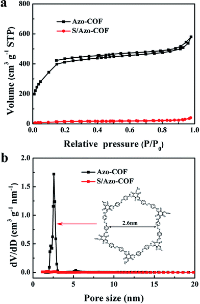 |
| | Fig. 2 (a) Nitrogen adsorption–desorption isotherms and (b) pore size distribution curves of the Azo-COF and S/Azo-COF composites. | |
Table 1 Physical characteristics of the Azo-COF and S/Azo-COF composites
| Sample |
BET surface area (m2 g−1) |
Pore volume (cm3 g−1) |
| Azo-COF |
1150 |
0.90 |
| S/Azo-COF |
56 |
0.06 |
In order to further understand the formation of sulfur in Azo-COF after undergoing heat treatment at 155 °C, the crystal properties of both sulfur and S/Azo-COF were characterized via X-ray diffraction (XRD), as shown in Fig. 3. For sulfur, a characteristic pattern with intense peaks appeared between 10° and 40° in accordance with the orthorhombic structure of sulfur, which is the most stable model under natural conditions. After sulfur was impregnated into Azo-COF, all of the sharp peaks of crystalline sulfur disappeared and only two broad peaks located around 15° and 27° belonging to Azo-COF were exhibited (Fig. S1†), indicating that most sulfur is highly dispersed in the pores of Azo-COF.6,35
 |
| | Fig. 3 XRD patterns of orthorhombic S and the S/Azo-COF composite. | |
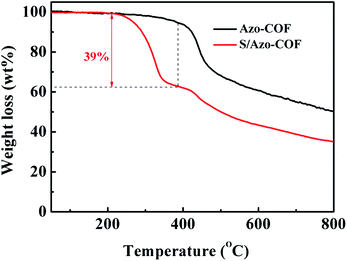
The thermal stability of Azo-COF and the S/Azo-COF composite was characterized via a TGA test. As shown in Fig. 4, for Azo-COF, when the temperature increased to nearly 400 °C, a weight loss can be observed, suggesting that Azo-COF is stable during the sulfur impregnation procedure at 155 °C. For S/Azo-COF, a new weight loss of nearly 39 wt% presented between 220 °C and 450 °C, which corresponds to the evaporation of sulfur in the composite materials. However, pure sulfur started to turn to vapor at 200 °C and quickly vanished below 350 °C (Fig. S2†). This output indicates that sulfur can remain in the pores of the host stably,36 which is in accordance with the XRD analysis. In other words, it is more difficult for the sulfur species to escape from the Azo-COF host, which is preferred in the Li–S battery cycling process.
 |
| | Fig. 4 TGA curves of the Azo-COF and S/Azo-COF composite. | |
Fig. 5 shows a typical CV curve with two reduction peaks and one oxidation peak of the S/Azo-COF composite, in which the two reduction peaks at about 2.3 V and 2.0 V can be ascribed to sulfur that was reduced to higher-order lithium PS (Li2Sn, n ≥ 4) and further reduced to lower-order lithium PS (Li2Sn, n < 4) respectively.37,38 The oxidation peak at about 2.4 V exhibits the reverse reaction from Li2S and/or Li2S2 to the final oxidation products of sulfur. Similar to previous reports,39–41 the reduction peak at 2.0 V exhibits the trend to higher potential, owing to the redistribution of sulfur species that can enhance the electrochemical reversibility. Meanwhile, no obvious decay can be seen from both the oxidation and reduction peaks’ intensity, further demonstrating that the sulfur species can be confined well in the Azo-COF host.
 |
| | Fig. 5 CV curves of Azo-COF electrodes at a scanning rate of 0.1 mV s−1 ranging from 1.5 to 2.8 V with 5 cycles. | |
In order to clarify the advantage of the Azo-COF structure, the cycling performance of the S/Azo-COF cathode was investigated at a C-rate of 0.1C (1C = 1672 mA h g−1) between 1.5 and 2.8 V. As shown in Fig. 6a, a high original discharge capacity of 1536 mA h g−1, 91.9% of the theoretical capacity, was exhibited for the cell assembly with the S/Azo-COF cathode, indicating that the poor electronic conductivity of Azo-COF has no negative influence upon the specific capacity output. Similar to previous reports,23,39,41–44 the discharge capacity decreases sharply in the first few cycles, which is attributed to the irreversible dissolution of PS. After that, a relatively stable capacity of 1082 mA h g−1 was achieved after 10 conditioning cycles. Within the next 90 cycles, a high discharge capacity of 741 mA h g−1, corresponding to nearly 70% capacity retention, remained even in a typical electrolyte (1 M LiTFSI in DME/DOL (1:1 v/v)) without LiNO3 as an additive, which was calculated from the tenth cycle. What’s more, the galvanostatic charge–discharge curves with two obvious discharge plateaus around 2.3 V and 2.1 V at a C-rate of 0.1C for the S/Azo-COF cathode are shown in Fig. 6b. In general, the two plateaus can be ascribed to a two-step discharge process from sulfur to high-order lithium PS and further lithiation to Li2S/Li2S2.45 The low voltage drop and small capacity loss after ten cycles demonstrate that PS can be confined well in the Azo-COF host. In addition, when the C-rate was increased to 1C, a high initial discharge capacity of 1044 mA h g−1 was still presented and a capacity of 602 mA h g−1 was maintained (Fig. 6c). Such good cycling performance of S/Azo-COF electrode can be mainly attributed to the relatively large specific surface, pore volume and porous distribution, which can absorb PS in the nanopores of Azo-COF effectively. Even though the performance can hardly compare with traditional carbon-based hosts with large specific surface area and pore volume,10,14 still a great progress in hosts based on COFs.32,33
 |
| | Fig. 6 Electrochemical properties of the S/Azo-COF electrodes. (a) Cycling performance of S/Azo-COF electrode at 0.1C. (b) Discharge/charge curves of the S/Azo-COF electrode at different cycles at 0.1C. (c) Cycling performance of the S/Azo-COF electrode at a high rate of 1C. | |
The C-rate behavior of S/Azo-COF was evaluated via galvanostatic charge–discharge at different C-rates ranging from 0.1 to 2C. As shown in Fig. 7a, with increasing C-rate, the discharge capacity decreased gradually, which can be mainly attributed to a polarization effect. For example, when the C-rate increased to 2C from 0.1C, the potential between the charge plateau and the second discharge plateau increased sharply from 148 to 547 mV, which is harmful for capacity output (Fig. 7c). Even so, a high rate capacity of 770 mA h g−1 remained at a C-rate of 2C (Fig. 7b), further suggesting excellent rate performance.
 |
| | Fig. 7 Electrochemical properties of the S/Azo-COF electrode. (a) and (b) C-rate performance for the S/Azo-COF electrode at various C-rates from 0.1 to 2C. (c) Charge/discharge profiles for S/Azo-COF at various C-rates from 0.1 to 2C. (d) Schematic illustration of a typical voltage profile. (e) and (f) The dependence of U1 and Q2/Q1 on the C-rate (data are collected from (c)). | |
In order to further understand the relationship between electrochemical performance and the Azo-COF pore distribution, two parameters of U1 and Q2/Q1 were introduced. U1, the onset potential of the plateau around 2.3 V, can reflect the interfacial kinetics between carbon and sulfur. Q1 and Q2 represent the partial discharge capacity of Q0, the theoretical specific capacity of 1675 mA h g−1, at the plateau around 2.3 V and 2.1 V as follows (Fig. 7d):
| | |
Plateau around 2.3 V:
|
(1)
|
| Q1 = 1/4Q0, Q0 = 1672 mA h g−1; |
| 2S42− + (12 − 2n)e− + (16 − 2n)Li+ ↔ nLi2S2 + (8 − 2n)Li2S |
| Q2 = (3/4 − n/8)Q0, 0 ≤ n ≤ 4, 1 ≤ Q2/Q1 ≤ 3. |
The plateau around 2.3 V corresponds to sulfur transforming to soluble PS. Due to 1/2 electron per S transferring, a 1/4 of the theoretical capacity will be output at this plateau. The other one around 2.1 V can be ascribed to further reducing PS to the final products of Li2S, during which the insoluble Li2S2 and Li2S species will precipitate on the surface of the lithium anode and greatly increase the resistance of Li+/e− transportation. Hence, Q2/Q1 should be a good indicator to show the ability of Li+/e− transport within the host.46,47 Fig. 7e and f show the evolution of U1 and Q2/Q1 for the S/Azo-COF electrode with the increase of C-rate. It should be mentioned that the data were collected from the charge/discharge profiles at different C-rates of S/Azo-COF, as shown in Fig. 7c. As can be clearly seen, with increasing C-rate, both U1 and Q2/Q1 show a trend to decrease, which can be mainly attributed to the growing impedance of both ohmic resistance and charge-transfer resistance. Nevertheless, U1 and Q2/Q1 of the S/Azo-COF electrode were still maintained at 2.23 V and 1.73 at a high C-rate of 2C, respectively, suggesting the relative superior reaction kinetics and fast Li+/e− transport for the S/Azo-COF electrodes, which agree well with the C-rate performance. Therefore, these results further highlight the merits of the Azo-COF host in facilitating electrolyte immersion and diffusion with a 1D regular pore distribution of 2.6 nm.
Conclusion
In summary, we have prepared Azo-COF with relatively large specific surface area, pore volume and regular pore distribution as a promising sulfur host for Li–S batteries. The small mesopores distributed at 2.6 nm can limit the PS diffusion while providing attractive 1D channels for facilitating Li+ transportation. On the basis of this intention, not only a high stable capacity of 741 mA h g−1 remained after 100 cycles at 0.1C but also a high rate capacity of 770 mA h g−1 at 2C was achieved. Even though the performance is not comparable to that of some carbon-based host systems, this research still presents the potential to arouse significant interest in the further development of Li–S batteries, and even other electrochemical devices such as capacitors and Li–O2 batteries.
Acknowledgements
The authors acknowledge the National Natural Science Foundation of China (Grant No. 21406221, 21273235 and 51403209), and the 100 Talents Program of the Dalian Institute of Chemical Physics, Chinese Academy of Sciences.
Notes and references
- A. Manthiram, Y. Fu, S. H. Chung, C. Zu and Y. S. Su, Chem. Rev., 2014, 114, 11751–11787 CrossRef CAS PubMed
 .
. - S. Zhang, K. Ueno, K. Dokko and M. Watanabe, Adv. Energy Mater., 2015, 1500212, DOI:10.1002/aenm.201500117 .
- X. Ji, K. T. Lee and L. F. Nazar, Nat. Mater., 2009, 8, 500–506 CrossRef CAS PubMed .
- A. Rosenman, E. Markevich, G. Salitra, D. Aurbach, A. Garsuch and F. F. Chesneau, Adv. Energy. Mater., 2015, 1500212, DOI:10.1002/aenm.201500212 .
- X. Ji and L. F. Nazar, J. Mater. Chem., 2010, 20, 9821–9826 RSC .
- B. Zhang, X. Qin, G. R. Li and X. P. Gao, Energy Environ. Sci., 2010, 3, 1531–1537 CAS .
- L. Sun, M. Li, Y. Jiang, W. Kong, K. Jiang, J. Wang and S. Fan, Nano Lett., 2014, 14, 4044–4049 CrossRef CAS PubMed .
- P. G. Bruce, S. A. Freunberger, L. J. Hardwick and J.-M. Tarascon, Nat. Mater., 2011, 11, 19–29 CrossRef PubMed .
- S. Moon, Y. H. Jung, W. K. Jung, D. S. Jung, J. W. Choi and D. K. Kim, Adv. Mater., 2013, 25, 6547–6553 CrossRef CAS PubMed .
- Y. Zhao, W. Wu, J. Li, Z. Xu and L. Guan, Adv. Mater., 2014, 26, 5113–5118 CrossRef CAS PubMed .
- J. T. Lee, Y. Zhao, S. Thieme, H. Kim, M. Oschatz, L. Borchardt, A. Magasinski, W. I. Cho, S. Kaskel and G. Yushin, Adv. Mater., 2013, 25, 4573–4579 CrossRef CAS PubMed .
- N. Brun, K. Sakaushi, L. Yu, L. Giebeler, J. Eckert and M. M. Titirici, Phys. Chem. Chem. Phys., 2013, 15, 6080–6087 RSC .
- L. Yu, N. Brun, K. Sakaushi, J. Eckert and M. M. Titirici, Carbon, 2013, 61, 245–253 CrossRef CAS PubMed .
- M. Wang, H. Zhang, Q. Wang, C. Qu, X. Li and H. Zhang, ACS Appl. Mater. Interfaces, 2015, 7, 3590–3599 CAS .
- C. Liang, N. J. Dudney and J. Y. Howe, Chem. Mater., 2009, 21, 4724–4730 CrossRef CAS .
- S. Xin, L. Gu, N. H. Zhao, Y. X. Yin, L. J. Zhou, Y. G. Guo and L. J. Wan, J. Am. Chem. Soc., 2012, 134, 18510–18513 CrossRef CAS PubMed .
- Q. Li, Z. Zhang, Z. Guo, Y. Lai, K. Zhang and J. Li, Carbon, 2014, 78, 1–9 CrossRef CAS PubMed .
- M. Rao, X. Geng, X. Li, S. Hu and W. Li, J. Power Sources, 2012, 212, 179–185 CrossRef CAS PubMed .
- D. Lee, J.-Y. Jung, M.-J. Jung and Y.-S. Lee, Chem. Eng. J., 2015, 263, 62–70 CrossRef CAS PubMed .
- R. Singhal, S. Chung, A. Manthiram and V. Kalra, J. Mater. Chem. A, 2015, 3, 4530–4538 CAS .
- Z. Wang, Y. Dong, H. Li, Z. Zhao, H. B. Wu, C. Hao, S. Liu, J. Qiu and X. W. Lou, Nat. Commun., 2014, 5, 5002, DOI:10.1038/ncomms6002 .
- G. Zhou, S. Pei, L. Li, D.-W. Wang, S. Wang, K. Huang, L.-C. Yin, F. Li and H.-M. Cheng, Adv. Mater., 2014, 26, 625–631 CrossRef CAS PubMed .
- H. Wang, Y. Yang, Y. Liang, J. T. Robinson, Y. Li, A. Jackson, Y. Cui and H. Dai, Nano Lett., 2011, 11, 2644–2647 CrossRef CAS PubMed .
- S. Yuan, Z. Guo, L. Wang, S. Hu, Y. Wang and Y. Xia, Adv. Sci., 2015, 1500071, DOI:10.1002/advs.201500071 .
- M. Xiao, M. Huang, S. Zeng, D. Han, S. Wang, L. Sun and Y. Meng, RSC Adv., 2013, 3, 4914–4916 RSC .
- Y. Dong, S. Liu, Z. Wang, Y. Liu, Z. Zhao and J. Qiu, Nanoscale, 2015, 7, 7569–7573 RSC .
- X. Liang, Y. Liu, Z. Wen, L. Huang, X. Wang and H. Zhang, J. Power Sources, 2011, 196, 6951–6955 CrossRef CAS PubMed .
- N. Nakamura, T. Yokoshima, H. Nara, T. Momma and T. Osaka, J. Power Sources, 2015, 274, 1263–1266 CrossRef CAS PubMed .
- W. Zhou, Y. Yu, H. Chen, F. J. DiSalvo and H. D. Abruna, J. Am. Chem. Soc., 2013, 135, 16736–16743 CrossRef CAS PubMed .
- Z. Wei Seh, W. Li, J. J. Cha, G. Zheng, Y. Yang, M. T. McDowell, P. C. Hsu and Y. Cui, Nat. Commun., 2013, 4, 1331, DOI:10.1038/ncomms2327 .
- X. Liang, C. Hart, Q. Pang, A. Garsuch, T. Weiss and L. F. Nazar, Nat. Commun., 2015, 6, 5682, DOI:10.1038/ncomms6682 .
- B. Guo, T. Ben, Z. Bi, G. M. Veith, X. G. Sun, S. Qiu and S. Dai, Chem. Commun., 2013, 49, 4905–4907 RSC .
- H. Liao, H. Ding, B. Li, X. Ai and C. Wang, J. Mater. Chem. A, 2014, 2, 8854–8858 CAS .
- S. Chandra, T. Kundu, S. Kandambeth, R. BabaRao, Y. Marathe, S. M. Kunjir and R. Banerjee, J. Am. Chem. Soc., 2014, 136, 6570–6573 CrossRef CAS PubMed .
- R. Elazari, G. Salitra, A. Garsuch, A. Panchenko and D. Aurbach, Adv. Mater., 2011, 23, 5641–5644 CrossRef CAS PubMed .
- C. Zhang, H. Wu, C. Yuan, Z. Guo and X. D. Lou, Angew. Chem., Int. Ed., 2012, 51, 9592–9595 CrossRef CAS PubMed .
- L. Miao, W. Wang, A. Wang, K. Yuan and Y. Yang, J. Mater. Chem. A, 2013, 1, 11659–11664 CAS .
- M. Wang, Y. Zhang, H. Zhang and H. Zhang, ChemPlusChem, 2014, 79, 919–924 CrossRef CAS PubMed .
- Z. Yang, H. Wang, X. Zhong, W. Qi, B. Wang and Q. Jiang, RSC Adv., 2014, 4, 50964–50968 RSC .
- X. Yang, N. Yan, W. Zhou, H. Zhang, X. Li and H. Zhang, J. Mater. Chem. A, 2015, 3, 15314–15323 CAS .
- Z. Li, Y. Jiang, L. Yuan, Z. Yi, C. Wu, Y. Liu, P. Strasser and Y. Huang, ACS Nano, 2014, 8, 9295–9303 CrossRef CAS PubMed .
- Z. Yang, H. Wang, X. Zhong, W. Qi, B. Wang and Q. Jiang, RSC Adv., 2014, 4, 50964–50968 RSC .
- I. Y. Choi, H. Kim and M. J. Park, RSC Adv., 2014, 4, 61333–61336 RSC .
- G. Zheng, Y. Yang, J. J. Cha, S. S. Hong and Y. Cui, Nano Lett., 2011, 11, 4462–4467 CrossRef CAS PubMed .
- C. Tang, Q. Zhang, M. Q. Zhao, J. Q. Huang, X. B. Cheng, G. L. Tian, H. J. Peng and F. Wei, Adv. Mater., 2014, 26, 6100–6105 CrossRef CAS PubMed .
- J. Zhou, R. Li, X. Fan, Y. Chen, R. Han, W. Li, J. Zheng, B. Wang and X. Li, Energy Environ. Sci., 2014, 7, 2715–2724 CAS .
- M.-S. Park, J.-S. Yu, K. J. Kim, G. Jeong, J.-H. Kim, Y.-N. Jo, U. Hwang, S. Kang, T. Woo and Y.-J. Kim, Phys. Chem. Chem. Phys., 2012, 14, 6796–6804 RSC .
Footnotes |
| † Electronic supplementary information (ESI) available. See DOI: 10.1039/c5ra16235a |
| ‡ Xiaofei Yang and Bin Dong contributed equally to this work. |
|
| This journal is © The Royal Society of Chemistry 2015 |
Click here to see how this site uses Cookies. View our privacy policy here. 


