Polyaniline and iron based catalysts as air cathodes for enhanced oxygen reduction in microbial fuel cells

Xinhua Tangab, Haoran Lic, Zhuwei Duc and How Yong Ng*a
aNational University of Singapore, Department of Civil and Environmental Engineering, Centre for Water Research, Singapore 117576, Singapore. E-mail: howyongng@nus.edu.sg; Fax: +65 67744202; Tel: +65 65164777
bNational University of Singapore, NUS Graduate School for Integrative Sciences and Engineering, Singapore 117456, Singapore
cChinese Academy of Sciences, Institute of Process Engineering, National Key Laboratory of Biochemical Engineering, Beijing 100190, China

Received 11th August 2015 , Accepted 14th September 2015

First published on 14th September 2015


Abstract

The catalyst for oxygen reduction in a cathode is vital for power production in microbial fuel cells (MFCs). In this study, non-precious metal catalysts were prepared by a high-temperature treatment of the iron containing polyaniline as both nitrogen and carbon precursor. These catalysts showed very positive onset potentials and less than 3% yield of hydrogen peroxide in the whole potential range, which matched the state-of-the-art Pt/C. The MFC with a bare cathode only produced a maximum power density of 1.32 W m−3, while the MFCs with a PANI900, PANI–Fe700, and PANI–Fe900 cathode had a maximum power density of 3.00 W m−3, 7.45 W m−3, and 12.54 W m−3, respectively. Physical and chemical characterizations of the catalysts indicated that iron coordinated with pyridinic nitrogen hosted in micropores was responsible for the high catalytic activity. These results demonstrate that these catalysts are excellent cathodes for MFCs due to their high catalytic activity, strong stability and low cost.

1. Introduction

The microbial fuel cell (MFC) is a bioelectrochemical system that exploits microbial catalysis to directly convert chemical energy in organic matter into electrical energy.1–4 As a promising environmental biotechnology, the MFC has developed considerably in the past decade for wastewater treatment, biochemical oxygen demand and toxicity detection, power supply, and chemical and fuel synthesis.5–10 The high cost of the noble metal cathode, however, severely impedes the large-scale applications of MFCs.

Oxygen is the best choice as electron acceptor for MFCs due to the positive redox potential, the harmlessness of the reduction product (H2O) and its virtually inexhaustible availability. So far, platinum-based cathodes have been commonly used in MFCs due to their high catalytic performance for oxygen reduction reaction. This expensive catalyst, however, can account for almost half of the total construction cost of the MFC reactor.11 The cost of MFC system needs to be reduced to improve its competition for other wastewater treatment technology such as aerobic treatment and fermentation.11,12 In addition, the scarcity of platinum also requires the development of novel alternatives. As a result, the exploration of non-precious metal catalyst with high catalytic activity for oxygen reduction is currently a major focus of MFC research to bring down the construction cost of MFCs.

Recently, transition metal–nitrogen–carbon catalysts (M/N/C) prepared under high temperature have attracted lots of attention due to their excellent catalytic activity and remarkable stability toward oxygen reduction in fuel cells.13–15 For M/N/C catalyst, surface nitrogen, transition metal and micropores are considered to be critical for the active catalytic sites formation on catalyst surface.14 Consequently, the catalytic activities of these materials strongly depend on the carbon and nitrogen sources and the synthesis condition. These catalysts have shown good electrocatalytic activity for oxygen reduction, such as the high selectivity of four-electron reaction pathway and the positive onset potential.13,15 A more positive onset potential means a smaller overpotential and a larger cell voltage output, which improves the cathode performance in a cell system. Further, the two-electron reaction competes with the four-electron reaction in oxygen reduction, which not only lowers the theoretical electrode potential, but also generates hydrogen peroxide, which causes damages to electrode material, membrane and even electrochemically active microorganisms.16 Therefore, a catalyst with excellent selectivity for four-electron reaction is desirable for enhanced cathode performance in MFCs. As a result, this type of catalyst may find its application as an ideal cathode catalyst for MFCs to bring down the construction cost and improve the cathode performance.

In this report, novel catalysts were prepared by pyrolyzing iron containing polyaniline (PANI) under high temperature in NH3 atmosphere. PANI was employed as both nitrogen and carbon precursor because it offered a uniform and enhanced distribution of nitrogen on the surface. These catalysts were comprehensively examined by field emission scanning electron microscope (FESEM), nitrogen physisorption, elemental analysis, X-ray photoelectron spectroscopy (XPS), and electrochemical measurement. These catalysts were further used as air cathodes to study their performance in MFCs. Besides, an explanation for the high catalytic activity toward oxygen reduction was proposed. This study demonstrated that these catalysts were excellent cathode for MFCs.

2. Materials and methods

2.1 Catalysts preparation

Two catalysts, labeled as PANI–Fe900 and PANI–Fe700, were prepared by heat treatment of iron incorporated polyaniline in NH3 under 900 °C and 700 °C respectively. In brief, distilled aniline (4.5 mL) and Fe2SO4 (0.15 g) were dispersed in H2SO4 solution (300 mL, 0.5 M) via stirring and the suspension was ice cooled below 5 °C. Then, (NH4)2S2O8 was trickled into the suspension to start the polymerization. When polymerization was completed, this dark green sample was leached in H2SO4 solution, rinsed completely with deionized (DI) water, and then dried in air. Lastly, the sample was heat-treated in NH3 atmosphere under high temperature (900 °C and 700 °C respectively) for 30 min and the catalysts were obtained. Another catalyst, labeled as PANI900, was also synthesized using the same pyrolysis method under 900 °C, but without the incorporation of iron.

2.2 Electrode preparation

The catalytic activity of these catalysts was measured by a glassy rotary ring disk electrode (RRDE). The RRDE was polished by aluminas to obtain a smooth surface, sonicated in Milli-Q water, and then dried in air.

Coating of catalyst onto RRDE and MFC cathodes (graphite felt) was prepared as previously described.17 First, catalyst powder was dispersed well in a mixture solution of Nafion and ethanol. Next, the ink solution was coated onto the RRDE or the graphite felt surface and dried in the air. For comparison, commercially available platinum supported on carbon black (Pt/C) was also coated onto RRDE and cathode surface. The loading of non-precious metal catalyst and Pt/C on RRDE were 0.6 mg cm−2 and 20 μgPt cm−2, respectively.

2.3 Air cathode MFC construction and operation

Single-chambered MFC reactors (empty bed volume of approximately 100 mL) were used in this study.18 Graphite felt served as anode at the bottom of the reactor, while graphite felt coated with catalysts worked as cathode at the top of the reactor. The as-prepared catalyst and the Pt/C catalyst loading on cathode were 2 mg cm−2 and 0.5 mgPt cm−2, respectively. A bare cathode without any coating was also employed for reference. The anode and cathode were connected via titanium wire with an external resistance of 500 Ω.

MFCs were inoculated with bacteria from another stably running MFC in our group.19 The electrolyte included KCl (0.13 g L−1), NaCl (2.9 g L−1), NH4Cl (0.31 g L−1), metal salt (12.5 mL L−1), vitamin (5 mL L−1) and phosphate buffer (50 mM, pH 7).20 Sodium acetate (10 mM), a commonly used substrate, was added into MFC reactors as electron donor.

MFCs were operated in a fed-batch mode at 30 °C and the feeding solutions were replaced once the voltage output fell below 40 mV, which was considered as the ending of a cycle for power generation.

2.4 Calculation and analysis

Field emission scanning electron microscopy (FESEM) (JSM-6701F, JEOL) was employed to study the morphology of the catalysts. Specific surface area and micropore area were determined by nitrogen physisorption (ASAP 2010, Micromeritics). Electron probe microanalyzer (JXA-8100, JEOL) was used to measure the iron content and element analyzer (Vario EL cube) was used to examine the nitrogen content in these catalysts. The electronic states of nitrogen were studied by XPS (ESCALab, 220i-XL).

Linear sweep voltammograms (LSV) using RRDE (PINE, 5.61 mm of disk diameter) was applied to study the catalytic activity of these catalysts toward oxygen reduction. The LSV tests were conducted using an electrochemical workstation (CHI, 760B) in a conventional three-electrode system in oxygen saturated H2SO4 solution (0.5 M). LSV was carried out with a potential scan rate of 10 mV s−1, and the disk rotating speed was 900 rpm. RRDE electrode coated with catalyst was the working electrode, whereas an Ag/AgCl electrode (KCl saturated) and a platinum foil electrode worked as the reference and the counter electrode, respectively. The ring potential was set at 1.0 V (vs. Ag/AgCl). All the potentials were later converted into the reversible hydrogen electrode (RHE) scale.

RRDE experiment was also used to investigate the selectivity of these materials toward oxygen reduction reaction. The four-electron selectivity was assessed by the yield percentage of hydrogen peroxide during oxygen reduction, which was determined by the equation: H2O2% = 200 × IR/(IR + NID), where ID was the disk current, IR was the ring current, and N was collection efficiency of the ring (37%).13,21

A data acquisition system was used to measure and store the cell voltage output (E). The maximum power densities were acquired by varying the external resistor (R) from 10 to 2000 Ω, when MFCs became steady in electricity generation. Power density (P) was measured by the equation on the basis of the total volume (V) of the reactor: P = E2/(R × V).

3. Results and discussion

3.1 Electrochemical characterization of the catalysts

Electrochemical measurements were conducted to study the catalytic activity as well as the associated reduction pathways of these catalysts toward oxygen reduction in comparison with Pt/C. Fig. 1a was the results of the LSV with a RRDE. The onset potential, a very important criterion for the evaluation of the catalytic activity, increased in the following order: PANI900 < PANI–Fe700 < PANI–Fe900 < Pt/C. The onset potential of PANI–Fe900 was as high as 0.92 V (vs. RHE), very close to the onset potential delivered by the state-of-the-art Pt/C. The onset potential of the cathode determined cell performance when the anode was fixed. Therefore, a more positive onset potential indicated a smaller overpotential, a higher cathode potential, and consequently a larger cell voltage. In this study, the high onset potential of PANI–Fe900 demonstrated that it had high catalytic activity toward oxygen reduction and that it was a good alternative for Pt/C.
image file: c5ra16148g-f1.tif
Fig. 1 Disk current (a) and H2O2 yield (b) plots during oxygen reduction reaction in oxygen saturated H2SO4 solution (0.5 M) (scan rate: 10 mV s−1; rotating speed: 900 rpm).

The oxygen reduction reaction pathway was also studied by the RRDE experiments. The hydrogen peroxide yield percentage (Fig. 1b) also increased in the following order: PANI900 < PANI–Fe700 < PANI–Fe900 < Pt/C. The hydrogen peroxide yield percentage of PANI900 and PANI–Fe700 was considerably larger than that of PANI–Fe900 and Pt/C. Particularly, the hydrogen peroxide yield of PANI–Fe900 was less than 3% in the full potential range, which matched the four-electron selectivity of the benchmark Pt/C.

The theoretical potential of the four-electron reaction of oxygen reduction is 1.229 V (vs. RHE) under standard condition, while the value is only 0.695 V (vs. RHE) in the two-electron reaction to form H2O2.22 The undesirable two-electron reaction competes with the target four-electron reaction, which causes the formation of a mixed theoretical potential lying between 0.695 V (vs. RHE) and 1.229 V (vs. RHE) under standard condition, depending on the occurring extent of each of the two reactions.23 The formation of mixed potentials can dramatically reduce the cathode potential and accordingly the cell voltage. Further, the generation of H2O2 causes damages to electrode material, membrane and even electrochemically active microorganisms, which limits the overall performance of MFCs.16

RRDE experiments revealed that H2O2 production of PANI–Fe900 was comparable to the yield of Pt/C. The less than 3% yield of hydrogen peroxide in the full potential range indicated that oxygen reduction reaction on PANI–Fe900 proceeded predominantly via the four-electron pathway. These results demonstrated that PANI–Fe900 exhibited very high selectivity for the four-electron reaction. Therefore, PANI–Fe900 was expected to improve the cathode potential, cell voltage and overall performance of MFCs.

3.2 Performance of the catalysts in MFCs

Following the electrochemical measurements, these catalysts were further used as cathodes in MFCs to study their performance for electricity production. Bare cathode without catalyst coating and Pt/C catalyst was also investigated as control in MFCs for comparison.

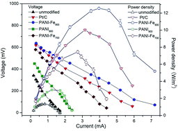
Fig. 2 was the polarization curves and the power density curves. As shown in Fig. 2 and Table 1, the maximum power density of the MFCs with PANI900, PANI–Fe700, and PANI–Fe900 were 3.00 W m−3, 7.45 W m−3, and 12.54 W m−3, respectively. This result was consistent with their catalytic activity in RRDE test. For comparison, the bare cathode MFC only produced a maximum power density of 1.32 W m−3, while the Pt/C cathode MFC had a maximum power density of 10.03 W m−3. These results demonstrated that these catalysts, especially PANI–Fe900, significantly enhanced the power density of MFCs. The enhancement was contributed to the improved cell voltage and reduced internal resistance (Table 1). Particularly, the open circuit voltage of the PANI–Fe900 cathode MFC was 0.72 V, whereas the corresponding value was 0.43 V for the bare cathode MFC and 0.73 V for the Pt/C cathode MFC. The internal resistance measured from the polarization curves was 84 Ω, 210 Ω and 99 Ω for the PANI–Fe900 cathode MFC, bare cathode MFC and Pt/C cathode MFC, respectively. The improved cell voltage, reduced internal resistance and high power density suggested that PANI–Fe900, which considerably enhanced the cathode performance compared with the bare cathode, was an excellent cathode in MFCs.


image file: c5ra16148g-f2.tif
Fig. 2 Polarization (solid symbols) and power density (empty symbols) curves of the MFCs with different cathodes.
Table 1 Air-cathode MFC performances with different cathode catalysts
Cathode Open circuit voltage (V) Internal resistance (Ω) Maximum power density (W m−3)
PANI–Fe900 0.72 84 12.54
PANI900 0.49 185 3.00
PANI–Fe700 0.65 126 7.45
Bare 0.43 210 1.32
Pt/C 0.73 99 10.03


The stability test of these catalysts was measured by running the MFCs over one month. During this period, the maximum power density of the PANI–Fe900 MFC declined from 12.54 W m−3 to 11.79 W m−3, approximately 6.0% deterioration. For comparison, the maximum power density of the Pt/C MFC decreased from 10.03 W m−3 to 9.39 W m−3, a drop of about 6.4%. This result demonstrated that PANI–Fe900 possessed good stability for long-term application in MFCs.

Besides catalytic activity and stability, the cost was another criterion for the evaluation of the cathode in MFCs.23 The cost of PANI–Fe900 prepared here was about 0.08 US dollar per gram, which was less than 1% of the commercially available Pt based catalyst (Table 2). Though the price of Fe2O3 was very close to PANI–Fe900, its power density in MFCs was much smaller than PANI–Fe900.18 Compared with nitrogen doped grapheme and nitrogen doped carbon nanosheet, PANI–Fe900 produced much higher power density.24,25 As mentioned above, Pt/C cathode accounts for nearly half of the construction cost of the MFC reactor, which limits the large-scale applications of this technology. Therefore, these low-cost and high-performance catalysts can be excellent candidates to replace the noble Pt/C to bring down the construction cost of MFCs.

Table 2 Cost and power density of some cathode catalysts in MFCs
Cathode catalysts Price (US dollar per g) Power density (W m−3) Reference
PANI–Fe900 0.08 12.54 This study
Pt 35.6 10.03 This study
Fe2O3 0.13 0.93 18
Nitrogen doped graphene N/A 6.98 24
Nitrogen doped carbon nanosheet N/A 5.13 25


3.3 Understanding of the high catalytic activity by physical and chemical characterization

Physical and chemical characterizations were conducted to explore the intrinsic properties of these catalysts, which helped to explain the high catalytic activity toward oxygen reduction reaction.

FESEM images of the as-prepared catalysts were shown in Fig. 3, which demonstrated that these catalysts exhibited highly microporous structures, especially the catalysts pyrolyzed under 900 °C. The specific surface area and the micropore area of these catalysts tested by the multiple point BET method were summarized in Table 3. PANI–Fe900 and PANI900 had quite high surface area and micropore area, while PANI–Fe700 displayed relatively lower values. These catalysts, however, only had a specific surface area of 12.8 m2 g−1 before pyrolysis treatment. Therefore, pyrolysis treatment in NH3 atmosphere under high temperature significantly enhanced surface area of these catalysts. The enhancement was the result of the etching effect of NH3, which reacted with carbon to produce volatile compounds and created large number of micropores.15 On the one hand, a high surface area provided sufficient interface for the adsorption and reduction reaction of oxygen. On the other hand, the active sites in these catalysts for oxygen reduction were considered to be hosted in micropores formed during pyrolysis.14,26 Therefore, a higher surface area and micropore area implied a higher catalytic activity. In this study, the specific surface area and micropore area of PANI–Fe900 were higher than PANI–Fe700, which elucidated the result that PANI–Fe900 exhibited higher catalytic activity than PANI–Fe700.


image file: c5ra16148g-f3.tif
Fig. 3 FESEM images of the non-precious metal catalysts: (a) PANI–Fe900; (b) PANI900; and (c) PANI–Fe700.
Table 3 Specific surface area, micropore area, iron and nitrogen content of the catalysts
Catalysts Surface area (m2 g−1) Micropore area (m2 g−1) Iron content (wt%) Nitrogen content (wt%) N species Binding energy (eV) Relative intensity (%) Content (wt%)
PANI–Fe900 769.8 570.5 0.72 5.26 Pyridinic N 398.3 37.5 1.97
Pyrrolic N 400.7 46.7 2.46
Oxidized N 403.8 15.8 0.83
PANI900 752.1 561.4 0 5.37 Pyridinic N 398.4 37.1 1.99
Pyrrolic N 400.7 32.9 1.77
Oxidized N 403.2 30.0 1.61
PANI–Fe700 541.5 388.6 0.68 5.92 Pyridinic N 398.4 22.8 1.35
Pyrrolic N 400.5 62.6 3.71
Oxidized N 403.5 14.6 0.86


Transition metal was also crucial for the catalytic activity of the catalysts prepared in this study. PANI–Fe900 and PANI900 showed similar micropore area, specific surface area, nitrogen content and even the relative intensity of each nitrogen species (Table 3). PANI–Fe900, however, exhibited considerably higher catalytic activity than PANI900, as suggested by the more positive onset potential, much higher selectivity for the four-electron reaction and higher power density in MFCs. One mechanism to explain the role of iron in Fe/N/C catalysts was that iron was coordinated with nitrogen in compounds such as FeN4 and FeN2 to form the active sites, which effectively facilitated oxygen reduction reaction.27–29 Therefore, iron served as active sites and played a critical role in enhancing oxygen reduction reaction in PANI–Fe900.

Nitrogen content measured by elemental analysis was listed in Table 3 for the three catalysts. Nitrogen content included in PANI is about 17%. The nitrogen content, however, decreased to about 5–6% after pyrolysis treatment. The decrease of nitrogen content was because of the gasification of nitrogen-containing fragments by NH3 under high temperature pyrolysis.

The electronic states of the nitrogen on catalysts were examined by XPS. The deconvoluted N 1s spectra showed in Fig. 4 exhibited that three nitrogen species were present in these catalysts, namely pyridinic nitrogen, pyrrolic nitrogen and oxidized nitrogen. The binding energy, relative intensity and content of these nitrogen species were summarized in Table 3. The relative intensity of pyridinic nitrogen in PANI–Fe900 (37.5%) and PANI900 (37.1%) was much higher than that in PANI–Fe700 (22.8%), while the relative intensity of pyrrolic nitrogen in PANI–Fe700 (62.6%) was much higher than the value in PANI–Fe900 (46.7%) and PANI900 (32.9%).


image file: c5ra16148g-f4.tif
Fig. 4 The deconvoluted high resolution N 1s X-ray photoelectron spectra for the catalysts: (a) PANI–Fe900; (b) PANI900; and (c) PANI–Fe700.

Nitrogen was essential for the catalysis of oxygen reduction reaction in M/N/C catalysts. As mentioned above, transition metal coordinated with nitrogen to form the catalytic active sites.14,28 Jaouen et al. prepared 19 types of M/N/C catalysts with nitrogen content in the range of 0.3% to 2.5%, and they demonstrated that the catalytic activity increased in proportion to nitrogen content in these materials, as higher nitrogen content resulted in higher active site density.28 The highest onset potential was about 0.8 V (vs. RHE) in H2SO4 solution (0.5 M) in that report, while the onset potential reached 0.92 V (vs. RHE) in this study. The nitrogen content of the catalysts prepared here was about 5–6%, which explained their high performance for oxygen reduction.

Previous studies of M/N/C catalysts revealed that the active sites were made of pyridinic nitrogen, rather than pyrrolic nitrogen or oxidized nitrogen hosted in micropores.14,28,30,31 Pyridinic nitrogen was able to coordinate the iron to form the active sites, which reduced the oxygen primarily via the four-electron pathway.13,29 Besides, pyridinic nitrogen could impart a positive charge on neighboring carbon atoms, and this charge delocalization could alter oxygen adsorption from the typical end-on chemisorption (Pauling model) to side-on chemisorption (Yeager model), which efficiently weakened the bonding of O–O and facilitates oxygen reduction rate.32 In this study, PANI–Fe900 displayed higher pyridinic nitrogen content and lower pyrrolic and oxidized nitrogen content than PANI–Fe700. Therefore, the fact that PANI–Fe900 exhibited higher catalytic activity than PANI–Fe700 was due to the higher pyridinic N content, because higher pyridinic N content meant higher active site density.

The positive onset potential, the excellent selectivity of the four-electron reaction pathway and the high performance in MFCs demonstrated that these catalysts were highly active toward oxygen reduction. This high electrocatalytic activity was due to the active sites formed by iron coordinated with pyridinic nitrogen in micropores during pyrolysis at high temperature. Therefore, microporous structure, iron and pyridinic nitrogen were the key requirements for these catalysts.

4. Conclusion

High-performance catalysts toward oxygen reduction in MFCs were prepared by pyrolyzing iron containing polyaniline at high temperature in NH3 atmosphere. These catalysts displayed very positive onset potential, excellent selectivity for the four-electron reaction, enhanced power density and good stability in MFCs. Physical and chemical characterization of the catalysts indicated that iron coordinated with pyridinic nitrogen hosted in micropores resulted in the high catalytic activity. This study demonstrates that these catalysts are excellent cathodes for MFC applications.

Acknowledgements

This work was supported by the Bill & Melinda Gates Foundation (OPP109475), the Environment & Water and Industry Development Council, Singapore (MEWR 651/06/159), and the China Ocean Mineral Resources R&D Association (No. DY125-15-T-08).

References

  1. H. Moon, I. S. Chang and B. H. Kim, Bioresour. Technol., 2006, 97, 621–627 CrossRef CAS PubMed .
  2. B. E. Logan, Nat. Rev. Microbiol., 2009, 7, 375–381 CrossRef CAS PubMed .
  3. L. M. Tender, C. E. Reimers, H. A. Stecher, D. E. Holmes, D. R. Bond, D. A. Lowy, K. Pilobello, S. J. Fertig and D. R. Lovley, Nat. Biotechnol., 2002, 20, 821–825 CrossRef CAS PubMed .
  4. E. R. Zhang, W. Xu, G. W. Diao and C. D. Shuang, J. Power Sources, 2006, 161, 820–825 CrossRef CAS PubMed .
  5. V. R. Nimje, C. Y. Chen, H. R. Chen, C. C. Chen, Y. M. Huang, M. J. Tseng, K. C. Cheng and Y. F. Chang, Bioresour. Technol., 2012, 104, 315–323 CrossRef CAS PubMed .
  6. L. Zhuang, Y. Yuan, Y. Q. Wang and S. G. Zhou, Bioresour. Technol., 2012, 123, 406–412 CrossRef CAS PubMed .
  7. I. S. Chang, H. Moon, J. K. Jang and B. H. Kim, Biosens. Bioelectron., 2005, 20, 1856–1859 CrossRef CAS PubMed .
  8. Y. F. Zhang and I. Angelidaki, Biosens. Bioelectron., 2012, 35, 265–270 CrossRef CAS PubMed .
  9. K. Dong, B. Y. Jia, C. L. Yu, W. B. Dong, F. Z. Du and H. Liu, Biosens. Bioelectron., 2013, 41, 916–919 CrossRef CAS PubMed .
  10. S. E. Oh and B. E. Logan, Water Res., 2005, 39, 4673–4682 CrossRef CAS PubMed .
  11. R. A. Rozendal, H. V. M. Hamelers, K. Rabaey, J. Keller and C. J. N. Buisman, Trends Biotechnol., 2008, 26, 450–459 CrossRef CAS PubMed .
  12. P. L. McCarty, J. Bae and J. Kim, Environ. Sci. Technol., 2011, 45, 7100–7106 CrossRef CAS PubMed .
  13. G. Wu, K. L. More, C. M. Johnston and P. Zelenay, Science, 2011, 332, 443–447 CrossRef CAS PubMed .
  14. M. Lefevre, E. Proietti, F. Jaouen and J. P. Dodelet, Science, 2009, 324, 71–74 CrossRef CAS PubMed .
  15. S. Kim, K. Nahm and P. Kim, Catal. Lett., 2012, 1244–1250 CrossRef CAS .
  16. S. Z. Li, Y. Y. Hu, Q. Xu, J. Sun, B. Hou and Y. P. Zhang, J. Power Sources, 2012, 213, 265–269 CrossRef CAS PubMed .
  17. S. Cheng, H. Liu and B. E. Logan, Environ. Sci. Technol., 2006, 40, 364–369 CrossRef CAS .
  18. P. Wang, B. Lai, H. Li and Z. Du, Bioresour. Technol., 2013, 134, 30–35 CrossRef CAS PubMed .
  19. X. H. Tang, K. Guo, H. R. Li, Z. W. Du and J. L. Tian, Bioresour. Technol., 2011, 102, 3558–3560 CrossRef CAS PubMed .
  20. D. R. Lovley and E. J. P. Phillips, Appl. Environ. Microbiol., 1988, 54, 1472–1480 CAS .
  21. M. B. Vukmirovic, J. Zhang, K. Sasaki, A. U. Nilekar, F. Uribe, M. Mavrikakis and R. R. Adzic, Electrochim. Acta, 2007, 52, 2257–2263 CrossRef CAS PubMed .
  22. F. Zhao, F. Harnisch, U. Schrorder, F. Scholz, P. Bogdanoff and I. Herrmann, Environ. Sci. Technol., 2006, 40, 5193–5199 CrossRef CAS .
  23. F. Harnisch and U. Schroder, Chem. Soc. Rev., 2010, 39, 4433–4448 RSC .
  24. Y. Liu, H. Liu, C. Wang, S. X. Hou and N. Yang, Environ. Sci. Technol., 2013, 47, 13889–13895 CrossRef CAS PubMed .
  25. Q. Wen, S. Wang, J. Yan, L. Cong, Y. Chen and H. Xi, Bioelectrochemistry, 2014, 95, 23–28 CrossRef CAS PubMed .
  26. P. H. Matter, L. Zhang and U. S. Ozkan, J. Catal., 2006, 239, 83–96 CrossRef CAS PubMed .
  27. B. Vanwingerden, J. A. R. Vanveen and C. T. J. Mensch, J. Chem. Soc., Faraday Trans. 1, 1988, 84, 65–74 RSC .
  28. F. Jaouen, S. Marcotte, J. P. Dodelet and G. Lindbergh, J. Phys. Chem. B, 2003, 107, 1376–1386 CrossRef CAS .
  29. U. I. Koslowski, I. Abs-Wurmbach, S. Fiechter and P. Bogdanoff, J. Phys. Chem. C, 2008, 112, 15356–15366 CAS .
  30. R. Bashyam and P. Zelenay, Nature, 2006, 443, 63–66 CrossRef CAS PubMed .
  31. E. Proietti, F. Jaouen, M. Lefevre, N. Larouche, J. Tian, J. Herranz and J. P. Dodelet, Nat. Commun., 2011, 2, 416–425 CrossRef PubMed .
  32. K. P. Gong, F. Du, Z. H. Xia, M. Durstock and L. M. Dai, Science, 2009, 323, 760–764 CrossRef CAS PubMed .

This journal is © The Royal Society of Chemistry 2015
Click here to see how this site uses Cookies. View our privacy policy here.