New insights into electrolyte-component biased and transfer- and transport-limited charge recombination in dye-sensitized solar cells

Dong-Li Gao, Yi Wang*, Ping Zhang, Li-Min Fu, Xi-Cheng Ai and Jian-Ping Zhang
Department of Chemistry, Renmin University of China, Beijing, 100872, P. R. China. E-mail: gaoyangdongli@sina.com; ywang@ruc.edu.cn; zhangp1988spl@163.com; lmfu@chem.ruc.edu.cn; xcai@chem.ruc.edu.cn; jpzhang@chem.ruc.edu.cn; Tel: +86-10-62516560

Received 5th August 2015 , Accepted 29th September 2015

First published on 29th September 2015


Abstract

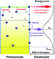
We carried out a time-resolved charge extraction (TRCE) study on the charge recombination dynamics of open-circuit dye-sensitized solar cells (DSSCs) by examining the temporal evolution of electron density with varying the concentration of the electrolyte component tert-butylpyridine (TBP). The charge recombination dynamics extracted from TRCE results exhibit distinctly different temporal behavior depending on the photovoltage or electron density. We proposed a theoretical model of electron density dependent charge recombination, which unifies the transport- and transfer-limited charge recombination mechanisms. This model, as rationalized by transient photovoltage (TPV) kinetics, can account well for the TRCE results. The relevance between electron transport and charge transfer in the recombination process was unraveled, and the electron density dependent pathway of charge recombination was elucidated.


1. Introduction

Dye-sensitized solar cells (DSSCs) based on nanocrystalline TiO2 have attracted remarkable academic and industrial interests because of their high power conversion efficiency (PCE) and great potential in low-cost and large-scale production.1–3 Till now, the PCE record of DSSCs has achieved 13%.4 Under light illumination, the excited dye molecules which are chemically adsorbed on the surface of TiO2 nanoparticles can sufficiently inject the photo-induced electrons into the conduction band of TiO2.5–9 Once the electrons percolate across the TiO2 layer and are collected by the fluorine-doped-tine-oxide (FTO) coated transparent electrode, the photocurrent can be possibly generated.10–12

However, during the charge transport in photoanode, considerable electrons may be consumed via charge recombination. Consequently, the competition between the charge transport and recombination plays a crucial role in determining the overall PCE of DSSCs. Because of the rapid regeneration of oxidized dyes by electrolyte (such as the iodide), charge recombination between oxidized dye molecules and electrons in photoanode is often negligible, and the neutralization between the electrons in TiO2 and the acceptors in electrolyte (e.g. the triiodide) is regarded as the dominant pathway of charge recombination.13–16 Charge recombination may take place at the mesoporous TiO2/electrolyte and/or FTO/electrolyte interfaces, depending on the components of electrolyte, configuration of photoanode, and the illumination condition. For the DSSCs constituted by TiO2-based photoanode and I/I3-based electrolyte, the TiO2/electrolyte interface is suggested to be the primary recombination site, as revealed by means of intensity modulated photovoltage spectroscopy (IMVS) and electrochemical impedance spectroscopy (EIS).17–19 Particularly, by testing the voltage-dependent charge transfer resistance, Lagemaat et al. give a strong evidence about the substantial role of charge recombination at TiO2/electrolyte interface in DSSCs.20 In this case, the process of charge recombination involves two aspects, i.e. the transport of electrons in photoanode to reach a recombination site and the transfer of electrons from TiO2 to electrolyte at recombination sites. Hereinafter, in order to distinguish these two processes, they will be termed as “electron transport” and “charge transfer” respectively. Previously, charge transfer was often treated as the rate determining step of recombination, based on which the dynamics of charge recombination was described by the model of transfer-limited recombination.21 Though the reaction mechanism of charge transfer is still in debate to date, by invoking this model, the proportional relation between recombination rate constant (kR) and the square of electron density (n2) was successfully interpreted.18,22–24 It should be noted that transfer-limited recombination was established by assuming charge recombination and electron transport are two independent processes, that's to say the influence of electron transport on charge recombination is negligible. Unfortunately, the subsequent studies revealed this hypothesis seems to be unreasonable. By means of transient photocurrent (TPC) and transient photovoltage (TPV), Kopidakis et al. found the dynamics of both electron transport and charge recombination varied simultaneously with the changing of Li+ concentration in electrolyte.13 What's more, the time constants of transport (τt) and of recombination (τn) showed nearly identical dependence upon electron density.25,26 These experiments indicated that charge recombination is strongly coupled with electron transport in photoanode, conflicting with the transfer limited recombination model. Based on this point, an alternative model i.e. the transport-limited recombination model was introduced, in which the rate of recombination is considered to be predominantly determined by electron transport in photoanode rather than charge transfer at TiO2/electrolyte interface.27 Obviously, the relevance between electron transport and charge recombination is well interpreted by this model; however there are still some imperfections while the most notable one is the over-simplification of treating the probable recombination pathways. As described by transport-limited recombination model, both of electron transport and charge transfer can only take place in conduction band, that's to say, the conduction band of TiO2 was the only recombination channel. Nevertheless, based on the theoretical simulation of open-circuit voltage decay (OCVD) kinetics in DSSCs, Bisquert et al. found that both of conduction band and surface states of TiO2 can act as recombination sites depending on the scale of electron density.28 In addition, these authors proposed a novel model claiming that charge recombination takes place dominantly through the surface states and conduction band, respectively, at low and high electron density.28 Very recently, some groups successively reported the observation of nonlinear recombination in DSSCs, implying the involvement of surface states in charge recombination.29,30 Besides, this model is also used to interpret the particular dependence of open-circuit voltage (VOC) on illumination intensity in DSSC, but more specific kinetics or dynamics studies are needed to confirm its reasonability, as the authors claimed, because the model invokes too many adjustable parameters for numerical fittings.31 On intuition, anyhow, the latest model mentioned above is unambiguous, since it can quantitatively interpret the result of OCVD on the base of Fermi–Dirac statistics. However, the rationalization of Fermi–Dirac statistics in OCVD measurement was then queried. Boschloo and Hagfeldt utilized numerous techniques, such as TPV, time-resolved charge extraction (TRCE), IMVS and OCVD, to study recombination dynamics of the same DSSC sample.32 Surprisingly, the results of TPV, TRCE and IMVS exhibited high agreements; while the OCVD result significantly deviates from the results of aforementioned measurements. The inaccuracy of OCVD was assigned to the utilization of the Fermi–Dirac statistics, in practically at low electron density.32 This interpretation is very possible, because Fermi–Dirac statistics is only appropriate for electrons in thermal equilibrium and this requirement was meet under the perturbation conditions (such as the experimental condition of TPV and IMVS).33,34 On the other hand, the OCVD measurement is often utilized to investigate the recombination dynamics with the decay of voltage from a high value to zero. In this case, the studied system especially at low electron density breaks the thermal equilibrium and dissatisfies the precondition of Fermi–Dirac statistics. In fact, the results indicated by OCVD at low electron density i.e. electron lifetime depended on voltage in reciprocal of the Gaussian,28 to our best knowledge, has never been observed by other means. Bisquert et al. have used Marcus theory to describe the kinetics of electron transfer both from conduction band and from surface trap states to electrolyte acceptors, but they neglected the truth that electrons in surface trap states are much more localized than those in conduction band, which may lead to a substantially lower charge transfer coefficient. As a result, the landscape of charge recombination via conduction band would be significantly different from that via surface states (vide infra).

In the present work, we directly explored the temporal evolution of electron density in DSSCs at open circuit, by means of TRCE, without invoking Fermi–Dirac statistics. In this case, we could study the recombination dynamics and avoid introducing errors from the improper adoption of Fermi–Dirac statistics. On the base of TRCE results, the mathematic expression of recombination rate constant as a function of electron density was derived. In addition, a physical model focusing on the description of charge recombination mechanisms in working DSSCs was put forth, which was experimentally verified by the results of TPV measurement. At last, the influence of electrolyte components on recombination dynamics was quantitatively analyzed.

2. Materials and methods

2.1 DSSC preparation

The DSSCs were fabricated by the hydrothermal method as previously reported.35 In the typical processes, hydroxypropyl cellulose (Aldrich) was first added to diethylene glycol with a concentration of ∼10 wt%, in which the P25 particles was subsequently added. After vigorous stirring, the homogeneous slurry was obtained, and was then spread onto the FTO glass substrate (TEC-8, LOF) by doctor-blade method, which resulted in the TiO2 film with a thickness of 10–14 μm. After being dried in air, the films were heated with a rate of 5 °C min−1 up to 450 °C and then maintained for 30 min. The films cooled to 80 °C were sensitized in ethanol solution of cis-bis (isothiocyanato)bis(2,2′-bipyridyl-4,4′-dicarboxylate)ruthenium(II) bis-tetrabutylammonium (N719, 3 × 10⁻⁴ M, Solaronix SA, Switzerland) for 24 h. The counter electrodes were platinized FTO. At last the electrolyte was injected and the sandwiched DSSC was obtained. In the experiments, two kinds of electrolyte were employed, as summarized below:

(1) Electrolyte of cell-1: LiI (0.05 M), I2 (0.03 M), tert-butylpyridine (TBP, 0.5 M), guandinethiocyanate (GuNCS, 0.1 M) and 1-butyl-3-methylimidazolium iodide (BMII, 1 M) in an acetonitrile–valeronitrile binary solvent (5[thin space (1/6-em)]:[thin space (1/6-em)]1, v/v).

(2) Electrolyte of cell-2: same to cell-1, but reducing the TBP to 0.01 M.

2.2 TRCE measurement

The measurement of TRCE was conducted as previously reported.36 The apparatus consisted of an analogy electric switching unit in serial connection with a sampling resistor (50 Ω), which were set as whole in parallel connection to the DSSC device. The DSSC was irradiated from the FTO side with pulsed laser at 532 nm (7 ns, 125 μJ per pulse). Under open-circuit condition, the Vph kinetics decayed over ∼10 s. A delay pulse generator (DG-535, Stanford Research Systems) was used to regulate the switching timing for charge extraction.

2.3 TPV measurement

The TPV measurement was performed following previous report.37 The DSSC sample was irradiated by a continuous-wave light emitting diode (LED, 530 ± 5 nm) under open-circuit to generate a desired photovoltage (Vph). Weak laser pulses (532 nm) were then applied to induce a small perturbation on Vph with ΔVph/Vph ≈ 5%. Electric signals were recorded by a digital oscilloscope (64Xs, Lecroy; input impedance, 1 MΩ). The TPV kinetics traces were fitted to ΔVph(t) = Vph + ΔVph(0)exp(−t/τn), yielding the electron lifetime τn at a photovoltage of Vph.

3. Models

A physical model focusing on the relevance between charge recombination dynamics and electron density in photoanode is put forth, as illustrated in Scheme 1, based on which the mechanism of charge recombination is elucidated.
image file: c5ra15658k-s1.tif
Scheme 1 Schematics of the processes of charge recombination in DSSCs. The dashed red arrows denote multiple-trapping evens of electrons between the conduction band and trap states, while the dashed purple arrow indicates electron hopping among surface states. The thicker red and purple arrows represent electron transfer from conduction band and surface states of photoanode to acceptors in electrolyte, respectively, in the cases of high and low electron densities.

At low electron density, most of electrons in photoanode populate in deep trap states and recombine with the acceptors in electrolyte predominately through the surface states (Scheme 1). The rate of recombination strongly depends on charge transfer kinetics at TiO2/electrolyte interface coinciding with the description of transfer limited recombination mechanism. Based on Marcus theory of single electron transfer, the rate constant of charge transfer is written by:

 
image file: c5ra15658k-t1.tif(1)
where ktr is the rate constant of charge transfer, kB is Boltzmann constant, T is temperature, ks is the intrinsic (energy-independent) coefficient of charge transfer between surface states and electrolyte, cox is the concentration of electron acceptors in electrolyte and E refers to the energy level of electrons in photoanode. Particularly, when E = Eox, the value of ktr turns to be the maximum:
 
image file: c5ra15658k-t2.tif(2)

At low electron density, as verified by numerous works, charge transfer is significantly slower than electron transport.38–40 On the other hand, the mechanism of electron transport in photoanode is generally described by multiple-trapping model or hopping model. In the former, conduction band of TiO2 is regarded as the only transport pathway and electrons in trap states should be thermally released to conduction band prior to their effective motion;41 whereas, the hopping model assumes that electron transport occurs by jumping among trap states.42 At low electron density, the multiple-trapping model may be void, because EFn is far below the conduction band and electrons in trap states are difficult to be excited into conduction band. Hence, hopping among trap states is suggested to be the dominant pathway of electron transport at low electron density. Considering the electrons trapped by surface states are intensely localized which results in slow electron transfer from TiO2 to electrolyte,43 it's reasonable to expect that the distribution of electrons at surface trap states will get equilibrium by rapid hopping preceding charge recombination. As thus, charge transfer dominantly takes place through the surface states with E = Eox, i.e. the fastest recombination channel (eqn (2)), because electrons at other energy levels will quickly hop to the surface states with E = Eox to sustain the electron equilibrium before they are consumed by electrolyte, as shown in Scheme 1. If so, the rate constant of recombination at low electron density turns to be a constant,

 
image file: c5ra15658k-t3.tif(3)

By contrary, the scenario of recombination at high electron density is quite different. Under this circumstance (see Scheme 1), EFn approaches to conduction band and multiple-trapping of electrons becomes significant, as a result, conduction band displaces the surface states as the dominant transport pathway,28 because the electrons are much more delocalized in conduction band than those in surface trap states, electron transfer from TiO2 to electrolyte via conduction band is also much faster than that via surface trap states.43 What's more, the rate of charge transfer via conduction band is even faster than electron transport, which leads the electron transport but not charge transfer to be the rate-determining step of recombination, following the description of transport-limited recombination mechanism. Based on multiple-trap theory and the continuity equation, the rate constant of transport-limited recombination can be derived as below,44

 
image file: c5ra15658k-t4.tif(4)
where k0 is recombination rate constant of free electrons in conduction band, Nc is the effective density of states in conduction band, Nt is the total density of trap states, α is the tail parameter of the energetic distribution of trap states and β is reaction order of free electrons in conduction band.

On the strength of the derived kRn relations (eqn (3) and (4)), the evolution of electron density can be obtained. In general, the expression of recombination rate is written as:

 
image file: c5ra15658k-t5.tif(5)

At low electron density, recombination rate is limited by charge transfer via surface trap states, and the kRn relation is written by eqn (3). Combining eqn (3) with eqn (5), one can obtain the temporal evolution of electron density as:

 
image file: c5ra15658k-t6.tif(6)
in which C1 is the integral constant.

In the same way, at high electron density where the recombination turns to be limited by electron transport, the evolution of electron density is obtained by inserting eqn (4) into eqn (5):

 
image file: c5ra15658k-t7.tif(7)
where C2 is the integral constant.

Eqn (6) and (7) indicate that electron density depends on time in exponential and power form, respectively, at low and high electron density.

4. Results and discussion

To begin with our work, two kinds of DSSCs with different electrolyte components were fabricated and the corresponding photovoltaic characteristics were shown in Fig. 1. The concentration of TBP in electrolyte was respectively 0.5 M and 0.01 M in cell-1 and cell-2, which gives rise to the significantly different photovoltaic performances. As well known, the reduction of TBP leads to the intimate contact between photoanode and cations (such as H+, Li+, etc.) in electrolyte; as a result, the conduction band of TiO2 is expected to be lowered.45 Therefore in the case of cell-2, the larger short-circuit current density (JSC) is suggested to arise from the enhanced dye-to-TiO2 electron injection, while the smaller VOC could be ascribed to the negative shift of energy level. In addition, based on the standard diode equation,46,47 we have fitted the JV curves previously and the fitting parameters indicated the faster recombination occurs in cell-2, which is another factor giving rise to the smaller VOC of cell-2.48 This is in accordance with the reported work, where the effect of TBP on suppressing charge recombination has been proved.24 In following text, the dynamics of charge recombination in cell-1 and cell-2 will be discussed in details.
image file: c5ra15658k-f1.tif
Fig. 1 Current density–voltage (JV) characteristics of cell-1 (black circle) and cell-2 (red circle). The solid curves are fitting results based on standard diode equation (see text for details).

In order to study the dynamics of charge recombination in the target samples, we investigate the temporal evolution of charge amount (Q)/electron density (n) under open-circuit by means of TRCE following the previous report,22 as depicted in Fig. 2. For each DSSC sample, the decay of n includes a fast component at high electron density (i.e. short delay time) followed by a slow one at low electron density (i.e. long delay time), based on the proposed model (Scheme 1), which are respectively fitted by the transport- (eqn (7)) and transfer-limited (eqn (6)) recombination mechanism.


image file: c5ra15658k-f2.tif
Fig. 2 Temporal evolution of charge amount (left coordinate) and electron density (right coordinate) at open circuit of cell-1 (a) and cell-2 (b). The open circles are experimental data and the solid curves are fitting results. Note that the fittings were conducted within the frameworks of transport-limited recombination model (blue curves) and transfer-limited recombination model (red curves), respectively, at short delay time (high electron density) and long delay time (low electron density).

On the base of temporal evolution of electron density, the dependence of recombination rate constant (kR) on electron density was quantitatively derived by invoking eqn (5). As illustrated in Fig. 3, kR is a constant at low electron density while increases significantly with n at high electron density (Fig. 3(a)). Particularly, in the case of high electron density, kRn relation could be described by a power function as shown by Fig. 3(b), where the linearity under log–log coordinate was clearly seen. Meanwhile, it's worth noting that the value of kR in cell-2 is obviously larger than that in cell-1, as discussed above, resulting from the variation of TBP concentration in electrolyte. Interestingly, at high electron density, one can see the slopes of kRn plots under log–log coordinate are nearly same. This issue will be interpreted by taking into account the effect of trap states distribution on recombination dynamics (vide infra).


image file: c5ra15658k-f3.tif
Fig. 3 Rate constant of recombination versus electron density of cell-1 (black) and cell-2 (red). (a) kRn at linear coordinate spanning a large range of electron density. (b) kRn at high electron density (>1.5 × 1016 cm−3) under log–log coordinate.

To get further insight into the charge recombination dynamics, we performed TPV measurement for the two cells, from which the relation between electron lifetime (τn) and voltage could be obtained. In addition, based on the reciprocal relationship between kR and τn, kRVph plots could be easily derived which were plotted in Fig. 4. Either in the case of cell-1 or cell-2, as seen from Fig. 4(a) and (b), kR is constant at low voltage (<0.4 V) while increases remarkably at high voltage (>0.4 V). More importantly, in the region of Vph > 0.4 V, kR exhibits exponential dependence upon Vph (Fig. 4(c) and (d)). By invoking the proposed model, kRVph relations were respectively fitted within the framework of transfer-limited recombination mechanism at low voltage and of transport-limited recombination mechanism at high voltage. It's noted that the scale of Vph was determined by the density of electrons in photoanode. The high coincide between the results of TPV and model fitting, once again, proved that the dynamics of charge recombination is limited by charge transfer at low electron density while by electron transport at high electron density.


image file: c5ra15658k-f4.tif
Fig. 4 Rate constant of recombination versus photovoltage of cell-1 (a) and cell-2 (b). The open-circles are experimental results extracted from the TPV measurements (see text for details), while the red and blue curves are the fitting results, which are conducted within the framework of transfer-limited recombination mechanism at low voltage and transport-limited recombination mechanism at high voltage respectively. Panels (c) and (d) are the experimental and fitting results at high voltage extracted from panels (a) and (b) which are plotted under semi-logarithm coordinates to clearly see the exponential dependence of kR upon Vph.

Having proved the reasonability of the proposed model, we now unravel the reasons of resulting in the distinct recombination dynamics between cell-1 and cell-2 in details. At low electron density, charge recombination is described by transfer-limited model. In this case, the kRn relation is expressed by eqn (3) which indicates the value of kR is determined by a series of variable parameters, i.e. T, ks, λ and cox. The redox specials are identical for target samples and the experimental temperature is same, which implies T, λ and cox are changeless, as a result, the difference of kR values totally arises from the different ks. It's noted that the TBP concentration in cell-2 (0.01 M) is much lower than that in cell-1 (0.5 M), which is the only difference between the target samples. Because TBP could block the contact between TiO2 and electrolyte which is beneficial for blocking charge transfer from TiO2 surface to electrolyte,45 one can now understand the enhancement of ks and kR in cell-2 due to the reduced concentration of TBP. On the other hand, the situation at high electron density is quite different. In this case, recombination dynamics is limited by electron transport in photoanode and kR depends on n in power (see Fig. 3(b)), which is now determined by k0, Nc, Nt, α and β (see eqn (4)). k0 is expected to be larger in cell-2 than that in cell-1, because the reduced TBP in cell-2 results in more intimate contact between TiO2 and electrolyte as discussed above. Consequently, the difference of the k0 values is one of the factors leading the different kR between cell-1 and cell-2. Meanwhile, the TiO2 photoanode, which is assembled by sintered P25 particles, is same for the target samples; therefore the difference of Nc is expected to be negligible. The rest parameters, Nt, α and β, are related to the distribution of bandgap trap states in TiO2, so we investigate the QV relations to check the density-of-states (DOS) in cell-1 and cell-2 by means of TRCE following reported method.36,37 In the region of 100–580 mV, as seen in Fig. 5, the QV plots are fitted by monoexponential functions exhibiting the same slope, which indicates the value of α is same for the target samples. Meanwhile, the slope of kRn under log–log coordinate, which is determined by both of α and β (eqn (4)), is also similar between cell-1 and cell-2, hence the value of β is expected to be identical. The value of Nt is suggested to be larger in cell-2 than that in cell-1, when taking the “physical trap states” into account.49 Compared to the structural trap states which may be caused by Ti4+(3d0) sites and/or oxygen vacancies,50,51 the electrostatic attraction between the electrons in TiO2 phase and the cations in electrolyte is termed as physical trap states.49 Because the higher TBP concentration in cell-1 is more effective to block the contact between TiO2 and cations in electrolyte, the larger Nt in cell-2 could be understood. In fact, as seen from Fig. 5, the QV plot of cell-2 shifts upward versus that of cell-1, which confirms the larger Nt in cell-2. As a conclusion, the difference between the values of kR in cell-1 and cell-2 at high electron density comprehensively results from the variation of k0 and Nt; while the same slope of kRn plots under log–log coordinate arises from the same α and β. To sum up, the effect of TBP concentration on charge recombination dynamics is summarized as below: at low electron density, TBP suppresses recombination by blocking the contact between TiO2 and electrolyte, which is responsible for the reduction of interfacial charge transfer coefficient; at high electron density, TBP influences recombination rate by hindering the contact between TiO2 and electrolyte on one hand, and by adjusting the DOS in photoanode on the other hand.


image file: c5ra15658k-f5.tif
Fig. 5 QVph plots of cell-1 (black circle) and cell-2 (red circle). The solid lines are monoexponential fitting in the region of 100–580 mV.

5. Conclusions

By means of TRCE, we studied the dynamics of charge recombination at different electron densities in DSSCs. The recombination dynamics exhibit two distinct behaviors depending on the scale of electron population in photoanode: at low electron density, the rate constant of recombination is fixed; while at high electron density, the rate constant of recombination increases with electron density in a power-law. Within the framework of transfer- and transport-limited recombination mechanisms, a physical model focusing on the relevance between charge transport and recombination was put forth. Based on the this model, the dynamics of recombination is suggested to be dominated by charge transfer at TiO2/electrolyte interface at low electron density while by electron transport in photoanode at high electron density, which interprets the dependence of recombination rate constant on electron density as revealed by TRCE results. In addition, TPV measurement was performed to study the voltage-dependent recombination rate at different light intensities, of which the results show high agreement with the proposed model. At last, combining the DOS distribution of trap states with recombination dynamics, the effect of TBP on recombination rate was discussed in details. That is, TBP impacts recombination rate by impeding the contact between TiO2 and electrolyte and reducing the total density of trap states.

Acknowledgements

This work was supported by the Natural Science Foundation of China (Grant No. 21133001, 21173266, 21373268 and 21473250), and by the Fundamental Research Funds for the Central Universities and the Research Funds of Renmin University of China (Grant No. 10XNI007 and 11XNJ021).

References

  1. B. O'Regan and M. Grätzel, Nature, 1991, 353, 737 CrossRef PubMed.
  2. M. K. Nazeeruddin, A. Kay, I. Rodicio, R. Humphrybaker, E. Muller, P. Liska, N. Vlachopoulos and M. Grätzel, J. Am. Chem. Soc., 1993, 115, 6382 CrossRef CAS.
  3. A. Yella, H.-W. Lee, H. N. Tsao, C. Yi, A. K. Chandrian, M. K. Nazeeruddin, E. W.-G. Diau, C.-Y. Yeh, S. M. Zakeeruddin and M. Grätzel, Science, 2011, 334, 629 CrossRef CAS PubMed.
  4. S. Mathew, A. Yella, P. Gao, R. Humphry-Baker, B. F. E. Curchod, N. Ashari-Astani, I. Tavernelli, U. Rothlisberger, M. K. Nazeeruddin and M. Grätzel, Nat. Chem., 2014, 6, 242–247 CrossRef CAS PubMed.
  5. C. J. Barbé, F. Arendse, P. Comte, M. Jirousek, F. Lenzmann, V. Shklover and M. Grätzel, J. Am. Ceram. Soc., 1997, 80, 3157 CrossRef PubMed.
  6. D. Kuang, S. Ito, B. Wenger, C. Klein, J. E. Moser, R. Humphry-Baker, S. M. Zakeeruddin and M. Grätzel, J. Am. Chem. Soc., 2006, 128, 4146 CrossRef CAS PubMed.
  7. G. Ramakrishna, D. A. Jose, D. K. Kumar, A. Das, D. K. Palit and H. N. Ghosh, J. Phys. Chem. B, 2005, 109, 15445 CrossRef CAS PubMed.
  8. G. Benkö, J. Kallioinen, J. E. I. Korppi-Tommola, A. P. Yartsev and V. Sundström, J. Am. Chem. Soc., 2002, 124, 489 CrossRef PubMed.
  9. J. B. Asbury, R. J. Ellingson, H. N. Ghosh, S. Ferrere, A. J. Nozik and T. Q. Lian, J. Phys. Chem. B, 1999, 103, 3110 CrossRef CAS.
  10. K. D. Benkstein, N. Kopidakis, J. van de Lagemaat and A. J. Frank, J. Phys. Chem. B, 2003, 107, 7759 CrossRef CAS.
  11. K. Fredin, J. Nissfolk and A. Hagfeldt, Sol. Energy Mater. Sol. Cells, 2005, 86, 283 CrossRef CAS PubMed.
  12. M. Ni, M. K. H. Leung, D. Y. C. Leung and K. Sumathy, Sol. Energy Mater. Sol. Cells, 2006, 90, 1331 CrossRef CAS PubMed.
  13. N. Kopidakis, K. D. Benkstein, J. van de Lagemaat and A. J. Frank, J. Phys. Chem. B, 2003, 107, 11307 CrossRef CAS.
  14. S. A. Haque, Y. Tachibana, D. R. Klug and J. R. Durrant, J. Phys. Chem. B, 1998, 102, 1745 CrossRef CAS.
  15. S. A. Haque, Y. Tachibana, R. L. Willis, J. E. Moser, M. Grätzel, D. R. Klug and J. R. Durrant, J. Phys. Chem. B, 2000, 104, 538 CrossRef CAS.
  16. B. A. Gregg, F. Pichot, S. Ferrere and C. L. Fields, J. Phys. Chem. B, 2001, 105, 1422 CrossRef CAS.
  17. A. Zaban, A. Meier and B. A. Gregg, J. Phys. Chem. B, 1997, 101, 7985 CrossRef CAS.
  18. G. Schlichthörl, S. Y. Huang, J. Sprague and A. J. Frank, J. Phys. Chem. B, 1997, 101, 8141 CrossRef.
  19. F. Cao, G. Oskam, P. C. Searson, J. M. Stipkala, T. A. Heimer, F. Farzad and G. J. Meyer, J. Phys. Chem. A, 1995, 99, 11974 CrossRef CAS.
  20. J. van de Lagemaat, N.-G. Park and A. J. Frank, J. Phys. Chem. B, 2000, 104, 2044 CrossRef CAS.
  21. J. Villanueva-Cab, G. Oskam and J. A. Anta, Sol. Energy Mater. Sol. Cells, 2010, 94, 45 CrossRef CAS PubMed.
  22. N. W. Duffy, L. M. Peter, R. M. G. Rajapakse and K. G. U. Wijayantha, J. Phys. Chem. B, 2000, 104, 8916 CrossRef CAS.
  23. A. C. Fisher, L. M. Peter, E. A. Ponomarev, A. B. Walker and K. G. U. Wijayantha, J. Phys. Chem. B, 2000, 104, 949 CrossRef CAS.
  24. S. Y. Huang, G. Schlichthörl, A. J. Nozik, M. Grätzel and A. J. Frank, J. Phys. Chem. B, 1997, 101, 2576 CrossRef CAS.
  25. L. M. Peter and K. G. U. Wijayantha, Electrochem. Commun., 1999, 1, 576 CrossRef CAS.
  26. L. M. Peter and K. G. U. Wijayantha, Electrochim. Acta, 2000, 45, 4543 CrossRef CAS.
  27. J. A. Anta, F. Casanueva and G. Oskam, J. Phys. Chem. B, 2006, 110, 5372 CrossRef CAS PubMed.
  28. J. Bisquert, A. Zaban, M. Greenshtein and I. M. Seró, J. Am. Chem. Soc., 2004, 126, 13550 CrossRef CAS PubMed.
  29. J. Bisquert and I. Mora-Seró, J. Phys. Chem. Lett., 2010, 1, 450 CrossRef CAS.
  30. J. Villanueva-Cab, H. Wang, G. Oskam and L. M. Peter, J. Phys. Chem. Lett., 2010, 1, 748 CrossRef CAS.
  31. P. Salvador, M. Gonzalez Hidalgo, A. Zaban and J. Bisquert, J. Phys. Chem. B, 2005, 109, 15915 CrossRef CAS PubMed.
  32. G. Boschloo and A. Hagfeldt, J. Phys. Chem. B, 2005, 109, 12093 CrossRef CAS PubMed.
  33. B. O'Regan and F. Lenzmann, J. Phys. Chem. B, 2004, 108, 4342 CrossRef.
  34. L. M. Peter and D. Vanmaekelbergh, in Advances in Electrochemical Science and Engineering, ed. R. C. Alkire and D. M. Kolb, Wiley Interscience, New York, 1999, vol. 6, ch. 2, p. 77 Search PubMed.
  35. D. P. Wu, Y. Wang, H. Dong, F. Zhu, S. Y. Gao, K. Jiang, L. M. Fu, J. P. Zhang and D. S. Xu, Nanoscale, 2013, 5, 324 RSC.
  36. Y. Wang, D. P. Wu, L. M. Fu, X. C. Ai, D. S. Xu and J. P. Zhang, Phys. Chem. Chem. Phys., 2014, 16, 11626 RSC.
  37. Y. Wang, D. P. Wu, L. M. Fu, X. C. Ai, D. S. Xu and J. P. Zhang, ChemPhysChem, 2015, 16, 2253 CrossRef CAS PubMed.
  38. R. Mohammadpour, A. I. Zad, A. Hagfeldt and G. Boschloo, Phys. Chem. Chem. Phys., 2011, 13, 21487 RSC.
  39. E. Guillén, L. M. Peter and J. A. Anta, J. Phys. Chem. C, 2011, 115, 22622 Search PubMed.
  40. F. Fabregat-Santiago, J. Bisquert, G. Garcia-Belmonte, G. Boschloo and A. Hagfeldt, Sol. Energy Mater. Sol. Cells, 2005, 87, 117 CrossRef CAS PubMed.
  41. F. W. Schmidlin, Solid State Commun., 1977, 22, 451 CrossRef.
  42. J. Bisquert, J. Phys. Chem. C, 2007, 111, 17163 CAS.
  43. M. Ansari-Rad, Y. Abdi and E. Arzi, J. Appl. Phys., 2012, 112, 074319 CrossRef PubMed.
  44. J. Bisquert and V. S. Vikhrenko, J. Phys. Chem. B, 2004, 108, 2313 CrossRef CAS.
  45. G. Boschloo, L. Häggman and A. Hagfeldt, J. Phys. Chem. B, 2006, 110, 13144 CrossRef CAS PubMed.
  46. K. Ishibashi, Y. Kimura and M. Niwano, J. Appl. Phys., 2008, 103, 094507 CrossRef PubMed.
  47. C. F. Zhang, J. C. Zhang, Y. Hao, Z. H. Lin and C. X. Zhu, J. Appl. Phys., 2011, 110, 064504 CrossRef PubMed.
  48. P. Zhang, Y. Wang, L.-M. Fu, X.-C. Ai and J.-P. Zhang, Acta Phys.-Chim. Sin., 2015, 31, 0001 Search PubMed.
  49. L. M. Peter, Acc. Chem. Res., 2009, 42, 1839 CrossRef CAS PubMed.
  50. R. F. Howe and M. Grätzel, J. Phys. Chem., 1987, 91, 3906 CrossRef CAS.
  51. T. L. Thompson and J. T. Yates, Chem. Rev., 2006, 106, 4428 CrossRef CAS PubMed.

This journal is © The Royal Society of Chemistry 2015
Click here to see how this site uses Cookies. View our privacy policy here.