Super long-life supercapacitor electrode materials based on hierarchical porous hollow carbon microcapsules

Fen Ran*ab, Xuanxuan Zhanga, Yuansen Liuc, Kuiwen Shena, Xiaoqin Niub, Yongtao Tana, Lingbin Konga, Long Kanga, Changan Xuc and Shaowei Chen*b
aState Key Laboratory of Advanced Processing and Recycling of Non-ferrous Metals, Lanzhou University of Technology, Lanzhou 730050, P. R. China. E-mail: ranfen@163.com
bDepartment of Chemistry and Biochemistry, University of California, 1156 High Street, Santa Cruz, California 95064, USA. E-mail: shaowei@ucsc.edu
cEngineering Research Center of Marine Biological Resource Comprehensive Utilization, Third Institute of Oceanography, State Oceanic Administration, Xiamen, 361005, P. R. China

Received 4th August 2015 , Accepted 8th October 2015

First published on 8th October 2015


Abstract

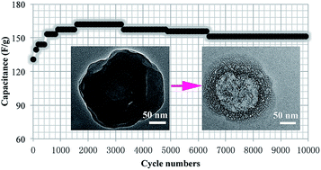
Remarkable supercapacitor electrodes with a high specific supercapacitance and a super long cycle life were achieved by using hierarchical porous hollow carbon microcapsules (HPHCMs) as active materials. HPHCMs were prepared by a facile chemical route based on pyrolysis of a soft sacrificial template involving a non-crosslinked core of poly(styrene-r-methylacrylic acid) and a crosslinked shell of poly(styrene-r-divinylbenzene-r-methylacrylic acid), which were synthesized by using traditional radical polymerization and emulsion polymerization. The results of scanning electron microscopy, transmission electron microscopy and Brunauer–Emmett–Teller characterizations revealed that HPHCM possessed the desired pore structure with apparent macro-/meso- and micropores, which not only provided a continuous electron-transfer pathway to ensure good electrical contact, but also facilitated ion transport by shortening diffusion pathways. As electrode materials for supercapacitor, a high specific capacitance of 278.0 F g−1 was obtained at the current density of 5 mA cm−2. Importantly, after 5000 potential cycles in 2 M KOH electrolyte at the discharge current density of 20 mA cm−2, the capacitance actually increased from 125 to 160 F g−1 and then remained 151 F g−1, corresponding to a capacitance retention of 120%, likely due to electrochemical self-activation.


1. Introduction

As a new class of energy storage devices, supercapacitors (also termed as non-faradic electrical energy storage devices) are different from traditional capacitors, which combine the advantages of both conventional dielectric capacitors and rechargeable batteries and can store high energy and transport high power within a very short period of time.1–3 Based on the energy storage mechanism, supercapacitors can be divided into two categories: electrochemical double-layer capacitors and pseudocapacitors.4,5 The performance of supercapacitors depends intimately on the physical and chemical properties of their electrode materials.6,7 In the past few years, carbon electrode materials for supercapacitors have been widely investigated, because of its high conductivity, lower resistance and good stability.8,9 Note that carbon materials are generally used for electric double layer capacitors, where the capacitance comes from the charge separation at an electrode/electrolyte interface.10,11 To enhance the capacitance performance, considerable efforts have been devoted to fabricating hierarchical porous carbons with macro-/micro- or mesopores.12,13 It has been proposed that macropores can act as bulk buffering reservoirs for electrolyte ions to minimize the diffusion distances to the interior surfaces of the pores, while meso- or micropores can provide a large accessible surface area for ion transport/charge storage, and can continuously increase charge accommodation.14,15 Thus, hierarchical porous structures with macro-/micro- or mesopores are strongly desired for high-performance supercapacitors.

Various synthetic techniques, such as sol–gel, hydrothermal, ultrasonic, nanocasting, coating, and so on,16,17 have been developed to prepare porous carbon materials, while the most common and effective route to construct nanoporous structures involves hard- and soft-templating methods, in which nanoporosity is generated by the removal of the hard or soft sacrificial components.18,19 In contrast, polymeric sacrificial blocks used in soft templating can be typically removed by thermal decomposition prior to carbonization without interfering with the chemistry of the resultant carbon.20 Block copolymers, such as poly(ethylene oxide)–poly(propylene oxide)–poly(ethylene oxide),21 polyacrylonitrile-b-poly(n-butyl acrylate),22 poly(styrene-b-(4-vinyl)pyridine), poly(isoprene-b-styrene-b-(4-vinyl)pyridine),23 and poly(butadiene-block-2-(dimethylamino)ethyl methacrylate),25 were often used as soft templates. For example, polyacrylonitrile-b-poly(n-butyl acrylate) has been used as a precursor to prepare nanoporous nitrogen-enriched carbons and used as a capacitor electrode which exhibited a capacitance of >30 uF cm−2.22 Nevertheless, such methods also have significant disadvantages: (i) the block copolymers used as precursors are typically synthesized via control/living polymerization under strict operating conditions, i.e., water-free and oxygen-free conditions;24–26 (ii) the pores obtained through removal of soft sacrificial templates of block copolymers are generally limited to meso- or micropores,27 whereas macro-/meso- or micropores mentioned above are generally desired for supercapacitors. Therefore, a number of challenges and difficulties need to be overcome in the large-scale production and application of these kinds of porous materials. As such, development of simple, fast and inexpensive methods is in urgent need to obtain hierarchical porous carbon materials with macro-/meso- or micropores.

In this paper, polymer precursor microspheres involving a non-crosslinked core of poly(styrene-r-methylacrylic acid) and a crosslinked shell of poly(styrene-r-divinylbenzene-r-methylacrylic acid) were synthesized by using the traditional radical polymerization and emulsion polymerization method, and further used as precursors to prepare hierarchical porous hollow carbon microcapsules (HPHCMs). The prepared HPHCM, with the hollow cores as macropores, acted as bulk buffering reservoirs for electrolytes to minimize the diffusion distances to the interior surfaces of the pores, while the meso- or micropores provided a large accessible surface area for ion transport/charge storage, and continuously increased charge accommodation. More importantly, the micropores might be activated via charge and discharge processes, which endowed the prepared materials with a considerably high specific capacitance and super long cycle performance.

2. Experimental

2.1. Chemicals

Styrene (St) and methylacrylic acid (MAA) were purchased from Aladdin Reagents Inc, and subject to distillation prior to use. Divinylbenzene (DVB) was purchased from J&K Scientific Ltd. Potassium persulfate (APS), dimethylformamide (DMF), alcohol and the other chemicals were purchased from Sinopharm Chemical Reagent Co. Ltd., and used as received.

2.2. Crosslinked and non-crosslinked core–shell polymer microspheres

In a typical synthesis, MAA was dispersed in H2O in a single-necked round-bottom flask, into which was added St in a dropwise fashion at room temperature under magnetic stirring in a nitrogen atmosphere. The mixture was then heated to 80 °C with the addition of APS where polymerization took place for 24 h. After being centrifuged and washed with both ethanol and H2O, the obtained polymer solution, APS, St, MAA and DVB were added to 150 mL H2O. The mixture was again heated to 80 °C for another 24 h. After the polymerization, the product was also centrifuged and washed with both ethanol and H2O. During the polymerizations, the molar ratio of monomers of MAA[thin space (1/6-em)]:[thin space (1/6-em)]St[thin space (1/6-em)]:[thin space (1/6-em)]APS is 5[thin space (1/6-em)]:[thin space (1/6-em)]20[thin space (1/6-em)]:[thin space (1/6-em)]0.6, and that of St[thin space (1/6-em)]:[thin space (1/6-em)]DVB is 20[thin space (1/6-em)]:[thin space (1/6-em)]0.6.

2.3. Hierarchical porous hollow carbon microcapsules

The powder synthesized above was firstly pre-oxidized at 320 °C in a muffle furnace for 5 h. After being cooled down to room temperature, the obtained product was pyrolyzed at 700 °C in a tube furnace under a nitrogen atmosphere at a temperature ramp of 5 °C min−1 for 2 h. The sample was further modified by using the nitric acid oxidation method. In a typical process, 0.1 g carbon powder was dispersed in 10 mL of nitric acid solution (65 wt%) where the reaction kept at 80 °C under refluxing process for 2 h. The sample was recovered and washed thoroughly with H2O until the pH was close to 7, and further dried at 60 °C under vacuum for 16 h.

2.4. Structure characterization

The microstructures and morphology were characterized by transition electron microscopy (TEM, JEOL, JEM-2010) and field emission scanning electron microscopy (SEM, JEOL, JSM-6701F). Pore structures of the samples were characterized by nitrogen adsorption/desorption experiments at 77 K (Micromeritics, ASAP 2010M). The surface area was calculated using the Brunauer–Emmett–Teller (BET) equation. Pore size distribution was calculated by the Barrett–Joyner–Halenda (BJH) method using the adsorption branch of the isotherm.

2.5. Electrode preparation

To prepare electrodes for electrochemical tests, the carbon prepared above, acetylene black and conducting graphite at a weight ratio of 80[thin space (1/6-em)]:[thin space (1/6-em)]7.5[thin space (1/6-em)]:[thin space (1/6-em)]7.5 was mixed and ground in an agate mortar. To this mixture, 5 wt% of poly (tetrafluoroethylene) was added together with a few drops of ethanol. The resulting paste was pressed at 10 MPa into nickel foam (ChangSha Lyrun New Material Co. Ltd., 90 PPI, 2 mm), and dried at 80 °C for 12 h. Each carbon electrode contained approximately 8 mg of electroactive material and had a geometric surface area of about 1 cm2.

2.6. Electrochemical measurements

In order to estimate the capacitive performance of electrode material, both three-electrode and two-electrode were fabricated.

Electrochemical measurements were conducted at room temperature in a traditional three-electrode configuration. The prepared electrode, a platinum gauze electrode, a saturated calomel electrode were used as the working, counter, and reference electrodes, respectively. The electrochemical tests were carried out with a CHI660C electrochemical workstation in a 1 M Na2SO4 aqueous solution at 25 °C. The corresponding specific capacitances were calculated from the discharging time and based on the formula C = (IΔt)/(mΔV), where C (F g−1) is the specific capacitance, I (A) is the discharge current, Δt (s) is the discharge time, ΔV (V) represents the potential drop during discharge process, and m (g) is the mass of the active material.28 The cyclic stability measurement was carried out on a Land cell tester for 5000 cycles.

Electrochemical capacitor (EC) was also assembled in a symmetrical two-electrode mode. The nickel foam and a porous nonwoven cloth were used as the current collector and separator in the process of preparing the electrodes. The working electrodes were prepared with using the same procedure as before and the areal mass loading of active material was about 4.0 mg cm−2. In this case, a 2 M aqueous KOH was used as electrolyte in electrochemical measurement. The gravimetric specific capacitance of supercapacitor cell (CEC) was calculated from the galvanostatic charge/discharge curves at different current densities according the following formula:

 
image file: c5ra15594k-t1.tif(1)
where CEC is the specific capacitance based on the mass of electroactive material (F g−1), I is the applied current (A), Δt is the discharging time (s), ΔV is the voltage of discharging process (V), and m is the total mass of the two-electrode materials (g).

In addition, the gravimetric energy and power density of the cell were the crucial parameter for the practical application, which can be estimated by the following equations:

 
image file: c5ra15594k-t2.tif(2)
 
image file: c5ra15594k-t3.tif(3)
where U is the cell voltage (V), Δt is the discharging time (s), E corresponds to the energy density (W h kg−1), and the P refers to the average power density (W kg−1).

3. Results and discussion

3.1. Preparation and characterization of materials

The polymer precursor microspheres (PPS) including a non-crosslinked core of poly(styrene-r-methylacrylic acid) and a crosslinked shell of poly(styrene-r-divinylbenzene-r-methylacrylic acid) were synthesized by using the traditional radical polymerization and emulsion polymerization method, as shown in the Experimental section. Scheme 1 shows the schematic illustration for the preparation of hierarchical porous hollow carbon microcapsules (HPHCM), which included dispersion in DMF, pre-oxidation (320 °C, 5 h) and subsequent pyrolysis (700 °C, 2 h) processes. After carbonization, as shown in the scheme, the non-crosslinked polymer core was removed to obtain the hollow structure; and the crosslinked polymer shell remained due to sufficient crosslinking and carbonization. Note that besides the macropores, a number of meso- and micropores were also obtained due to the formation of non-crosslinked polymer segments in the crosslinked polymer shell. As mentioned above, the polymerization is the traditional radical polymerization, so there might be a number of non-crosslinked polymer segments, which were also sacrificed to form porous structures. The different porous sizes, such as mesopores and micropores, were derived from the different length of these non-crosslinked polymer segments. That is, hierarchical porous hollow carbon microcapsules including macro, meso and micro pores were obtained by the pyrolysis of crosslinked and non-crosslinked core–shell polymer microspheres.
image file: c5ra15594k-s1.tif
Scheme 1 Illustration of fabrication of hierarchical porous hollow carbon microcapsules derived from crosslinked and non-crosslinked core–shell polymer microspheres.

The morphologies and structures of the PPS and HPHCM were first examined by SEM and TEM measurements, as shown in Fig. 1. The prepared PPS exhibited a uniform size with a diameter of about 260 nm and a relative smooth surface (Fig. 1a). The corresponding TEM image in Fig. 1b clearly shows that PPS was a solid. In order to confirm the structure of the crosslinked and non-crosslinked core–shell polymer microspheres, the PPS was immersed in DMF for 5 h to remove the non-crosslinked core. Fig. 1c and d (and Fig. S1a) depicts the TEM images of the crosslinked hollow polymer microcapsule, from which one can see that the polymer microcapsule also exhibited a uniform size with the diameter of the hollow core about 100 nm. Note that besides the hollow cores (macropores), there was no other type of pores in the polymer shell. The hollow polymer spheres used as precursor were well-shaped and well-dispersed. However, the as-prepared carbon spheres were squeezed together due to the pyrolysis treatment (see Fig. S1b). Hence, it is very difficult to find a whole image of the characterized structure by TEM method; and only the one separated from aggregates can be clearly seen. After being heated in 320 °C and 700 °C, respectively, as shown in Fig. 1e (see Fig. S1c and d), the HPHCM exhibited the similar structure of PPS. Because of molecular reaction and volume shrinking during the carbonization procedure, the size of the hollow core increased to about 120 nm. At the same time, a variety of meso-/micropores were formed in the carbon shell due to the removal of different polymer segments during the heat treatment (Fig. 1f).


image file: c5ra15594k-f1.tif
Fig. 1 (a and b) SEM and TEM images of PPS; (c and d) TEM images of PPS with the removal of polymer cores; (e and f) TEM images of HPHCM (St[thin space (1/6-em)]:[thin space (1/6-em)]DVB = 20[thin space (1/6-em)]:[thin space (1/6-em)]0.6).

Nitrogen sorption experiments were then performed to evaluate the overall porosity of the HPHCM sample, as shown in Fig. 2. The N2 uptake at pressures of P/P0 < 0.1 indicates the relative volume of the micropores. The N2 uptake to P/P0 ∼ 0.5 to 0.6 is indicative of the generation of mesopores. Indeed, an enlargement of the size and population of mesopores is observed. The sample showed type-IV isotherms. From a thermodynamic point of view, desorption branch is often used to derive the mesopore size distributions from the isotherm.29 The pore size distributions of HPHCM show mesopore diameters of 2–80 nm. BET measurements further proved that the carbon material possessed a structural feature including both mesopores and macropores. The BET surface area (SBET) of HPHCM is 353.34 m2 g−1, indicating fair porosity with the total pore volume of 0.218 m3 g−1. Such a pore structure can potentially offer enhanced electrolyte access to the high interfacial area, which may improve the charge transport and power capability. Meanwhile, ion-buffering reservoirs are formed in the larger macropores (above 100 nm), which can reduce the diffusion distances to the interior surfaces.


image file: c5ra15594k-f2.tif
Fig. 2 (a) Nitrogen adsorption/desorption isotherms and (b) corresponding pore size distribution of HPHCM (St[thin space (1/6-em)]:[thin space (1/6-em)]DVB = 20[thin space (1/6-em)]:[thin space (1/6-em)]0.6).

The molar ratio of St[thin space (1/6-em)]:[thin space (1/6-em)]DVB is very important in preparing HPHCMs. When the molar ratio decreased to 20[thin space (1/6-em)]:[thin space (1/6-em)]0.1, hollow carbon microcapsules were also obtained but collapsed completely (Fig. 3a); when the ratio was further decreased to 20[thin space (1/6-em)]:[thin space (1/6-em)]0.05, the morphology of the carbon became even less well-defined (Fig. 3b). In addition, similar morphologies can be obtained at the ratio of 20[thin space (1/6-em)]:[thin space (1/6-em)]5.


image file: c5ra15594k-f3.tif
Fig. 3 (a) SEM images of HPHCMs prepared with different St[thin space (1/6-em)]:[thin space (1/6-em)]DVB ratio. (a) 20[thin space (1/6-em)]:[thin space (1/6-em)]0.6; and (b) 20[thin space (1/6-em)]:[thin space (1/6-em)]0.05.

3.2. Electrochemical performance

Fig. 4a is the cyclic voltammograms (CV) of the prepared HPHCM in 2 mol L−1 KOH solution at scan rates from 5 to 50 mV s−1. The figure shows that these CV curves of the HPHCM electrode deviate from idealized double-layer behavior. With increasing sweep rates, the shape of the CV curves was not significantly changed, which suggests a highly reversible system. Fig. 4b shows the charge–discharge curves of HPHCM within a potential window of −1.0 to 0.0 V at various current densities. The figure indicated that the charge–discharge curves exhibited a shape like an isosceles triangle, indicating its electric double-layer capacitive behavior, in accordance with the CV curves. The specific capacitance values calculated from the discharge curves is 278, 261, 245, 232 and 206 F g−1 at the current density of 5, 10, 20, 30, 40, and 50 mA cm−2, respectively. When the current density increased to 50 mA cm−2, the specific capacitance retained 74.1% of that at a lower current density of 5 mA cm−2, revealing good retention capability of the materials. The slightly decrement of the specific capacitance at higher current densities is due to the insufficient mass transportation and the voltage drop at high current density.
image file: c5ra15594k-f4.tif
Fig. 4 (a) Cyclic voltammograms, (b) galvanostatic charge–discharge curves, (c) complex-plane impedance plot, and (d) plots of specific energy density vs. specific power density of HPHCM (St[thin space (1/6-em)]:[thin space (1/6-em)]DVB = 20[thin space (1/6-em)]:[thin space (1/6-em)]0.6) in 2 M KOH solution.

EIS test was also carried out over a frequency range from 10 kHz to 10 mHz to further investigate the capacitive behavior of HPHCM, as shown in Fig. 4c. In the high frequency region, the point intersecting with the real axis reflects the internal resistance (Rs) of the electrode material, which includes the total resistance of the ionic resistance of the electrolyte, the intrinsic resistance of active material, and the contact resistance at the active material/current collector interface. The small semicircle (the charge transfer resistance, Rct) was observed for the samples, which was associates with the surface properties of the porous electrode. The small diameter indicates low impedance on the electrode/electrolyte interfaces. In the low frequency region, the straight line represents the diffusive resistance (Warburg impedance) of the electrolyte in the porous structure. The electrode showed an angle higher than 45°, suggesting a lower Warburg impedance of HPHCM due to the effective nanoporous structure facilitating the transport of electrolyte ions.30,31 The figure shows that the HPHCM electrode exhibited a relatively low Rs of 1.03 Ω. The electrical conductivity suffers from a decrease with increasing porosity due to noncompatibility of conductive pathways or oxygen-containing functional groups.32,33 The capacitance values obtained from galvanostatic charge–discharge were further used to calculate the energy density (E) and the power density (P). Based on the equations of E = 1/2CmΔV2 and P = Et, the curves of E and P is also shown in Fig. 4d. It can be seen that the energy density dropped off with the increase of the power density.

Stability and reversibility of an electrode material are very important for its practical use in a supercapacitor. Thus, the cyclic performance of the prepared carbon material was further examined by galvanostatic charge–discharge tests for 10[thin space (1/6-em)]000 cycles at the discharge current density of 20 mA cm2, as shown in Fig. 5. It is interesting that the specific capacitance value of the HPHCM electrode gradually but obviously increased from 125 F g−1 to 160 F g−1 in the first 3200 cycles, which is far more dramatic than that has been observed in previous reports.34,35 Although the specific capacitance value slightly decreased after 3200 cycles, the specific capacitance remained at 151 F g−1 even after 10[thin space (1/6-em)]000 cycles, corresponding to a capacitance retention rate of 120%. The superior electrochemical performance of porous carbon materials can be attributed to its high specific surface area and unique hierarchical porous nanostructure, and the dramatic increase of specific capacitance during the charge–discharge cycles maybe attributed to the activation process of micropores.


image file: c5ra15594k-f5.tif
Fig. 5 Cycle life of HPHCM (St[thin space (1/6-em)]:[thin space (1/6-em)]DVB = 20[thin space (1/6-em)]:[thin space (1/6-em)]0.6) at the current density of 20 mA cm−2.

Since the HPHCM electrode material exhibited good capacitance stability, the performance after being charge-recharged 5000 cycles was further investigated, as shown in Fig. 6. The CV curves and galvanostatic charge–discharge curves were very similar to those of the first cycle. Rs of the electrode after 5000 cycles was 1.15 Ω, only slightly higher than that of the first cycle. It was also observed that the energy density dropped off with the increase of the power density.


image file: c5ra15594k-f6.tif
Fig. 6 (a) Cyclic voltammograms, (b) galvanostatic charge–discharge curves, (c) complex-plane impedance plot, and (d) plots of specific energy density vs. specific power density of HPHCM (St[thin space (1/6-em)]:[thin space (1/6-em)]DVB = 20[thin space (1/6-em)]:[thin space (1/6-em)]0.6) after being charge-recharged 5000 cycles in 2 M KOH solution.

The capacitive performance of hollow carbon was further measured based on the two-electrode configuration. Fig. 7 represents typical characterization in 2 M KOH electrolyte. The cyclic voltammetry (CV) curves in Fig. 7a exhibited nearly symmetrical rectangular shapes, indicative of an ideal capacitive behaviour. The galvanostatic charging–discharging curves of the symmetric capacitor at different current densities are shown in Fig. 7b. It can be seen that both charging and discharging curves remain a good symmetry, similar to the result of CV curves. At a low operation rate of 0.5 A g−1, the gravimetric specific capacitance of EC can reach to 42 F g−1.


image file: c5ra15594k-f7.tif
Fig. 7 Capacitive performances of a symmetric supercapacitor with modified hollow carbon as electrodes. (a) CV curves at different scan rate, (b) galvanostatic charging–discharging curves at different current density.

Fig. 8 presents the Ragone plot of symmetric capacitor in 2 M aqueous KOH. It is seen that the EC with symmetric hollow carbon electrode delivered the highest energy density of 5.83 W h kg−1 at a power density of 250 W kg−1 and maintained 3.125 W h kg−1 at a power density of 2500 W kg−1. Such an excellent capacitive performance can be ascribed to the unique porous nanostructure and the high specific surface area of hollow carbon. Taken together all the results demonstrate that the hollow carbon is promising as an advanced electrode material for supercapacitor applications.


image file: c5ra15594k-f8.tif
Fig. 8 Ragone plot of the symmetric supercapacitor showing the relation of energy density and power density.

4. Conclusions

In summary, we have successfully prepared a supercapacitor electrode with a high specific supercapacitance of 278 F g−1 and a remarkable cycle life by using hierarchical porous hollow carbon microcapsules (HPHCMs) as the active materials. HPHCMs were prepared by using a facile chemical route based on the pyrolysis of a soft sacrificial template involving a non-crosslinked core of poly(styrene-r-methylacrylic acid) and a crosslinked shell of poly(styrene-r-divinylbenzene-r-methylacrylic acid), which were synthesized by using traditional radical polymerization and emulsion polymerization methods. The desired pore structure of macro-/meso- and micropores improved the energy and power density. Furthermore, even after continuous operation for 5000 cycles in the 2 M KOH electrolyte at discharge current density of 20 mA cm2, the HPHCM supercapacitance actually increased from 125 to 160 F g−1 and then remained 151 F g−1, corresponding to a capacitance retention rate of 120%.

Acknowledgements

This work was supported by the National Natural Science Foundation of China (51203071, 51363014, 51463012 and 51362018), China Postdoctoral Science Foundation (2014M552509, 2015T81064), the Opening Project of State Key Laboratory of Polymer Materials Engineering (Sichuan University) (sklpme2014-4-25), the Program for Hongliu Distinguished Young Scholars in Lanzhou University of Technology (J201402), and the University Scientific Research Project of Gansu Province (2014B-025).

Notes and references

  1. M. F. El-Kady, V. Strong, S. Dubin and R. B. Kaner, Science, 2012, 335, 1326 CrossRef CAS PubMed.
  2. L. Zhao, L. Z. Fan, M. Q. Zhou, H. Guan, S. Y. Qiao, M. Antonietti and M.-M. Titirici, Adv. Mater., 2010, 22, 5202 CrossRef CAS PubMed.
  3. P. J. Hall and E. J. Bain, Energy Policy, 2008, 36, 4352 CrossRef PubMed.
  4. L. Z. Fan, Y. S. Hu, J. Maier, P. Adelhelm, B. Smarsly and M. Antonietti, Adv. Funct. Mater., 2007, 17, 3083 CrossRef CAS PubMed.
  5. K. Zhou, W. J. Zhou, X. J. Liu, Y. H. Sang, S. Z. Ji, W. Li, J. Lu, L. G. Li, W. H. Niu, H. Liu and S. W. Chen, Nano Energy, 2015, 12, 510 CrossRef CAS PubMed.
  6. J. R. Miller and P. Simon, Science, 2008, 321, 651 CrossRef CAS PubMed.
  7. W. J. Zhou, K. Zhou, X. J. Liu, R. Hu, H. Liu and S. W. Chen, J. Mater. Chem. A, 2014, 2, 7250 CAS.
  8. P. Simon and Y. Gogotsi, Nat. Mater., 2008, 7, 845 CrossRef CAS PubMed.
  9. A. S. Arico, P. Bruce, B. Scrosati, J.-M. Tarascon and W. van Schalkwijk, Nat. Mater., 2005, 4, 366 CrossRef CAS PubMed.
  10. B. E. Conway, Electrochemical Supercapacitors: Scientific Fundamentals and Technological Applications, Kluwer Academic/Plenum Publishers, New York, 1999 Search PubMed.
  11. M. Q. Zhao, Q. Zhang, J. Q. Huang, G. L. Tian, T. C. Chen, W. Z. Qian and F. Wei, Carbon, 2013, 54, 403 CrossRef CAS PubMed.
  12. D. W. Wang, F. Li, M. Liu, G. Q. Lu and H. M. Cheng, Angew. Chem., Int. Ed., 2007, 120, 379 CrossRef PubMed.
  13. C. Largeot, C. Portet, J. Chmiola, P. L. Taberna, Y. Gogotsi and P. Simon, J. Am. Chem. Soc., 2008, 130, 2730 CrossRef CAS PubMed.
  14. H. Jiang, J. Ma and C. Z. Li, Adv. Mater., 2012, 30, 4197 CrossRef PubMed.
  15. Q. Mahmood, H. J. Yun, W. S. Kim and H. S. Park, J. Power Sources, 2013, 235, 187 CrossRef CAS PubMed.
  16. Z. S. Wu, Y. Sun, Y. Z. Tan, S. B. Yang, X. L. Feng and K. Mullen, J. Am. Chem. Soc., 2012, 134, 19532 CrossRef CAS PubMed.
  17. S. Nardecchia, D. Carriazo, M. L. Ferrer, M. C. Gutierrez and F. del Monte, Chem. Soc. Rev., 2013, 42, 794 RSC.
  18. D. C. Wu, C. M. Hui, H. C. Dong, J. Pietrasik, H. J. Ryu, Z. H. Li, M. J. Zhong, H. K. He, E. K. Kim, M. Jaroniec, T. Kowa-lewski and K. Matyjaszewski, Macromolecules, 2011, 44, 5846 CrossRef CAS.
  19. R. Liu, S. M. Mahurin, C. Li, R. R. Unocic, J. C. Idrobo, H. Gao, S. J. Pennycook and S. Dai, Angew. Chem., Int. Ed., 2011, 123, 6931 CrossRef PubMed.
  20. Y. Fang, Y. Y. Lv, R. C. Che, H. Y. Wu, X. H. Zhang, D. Gu, G. F. Zheng and D. Y. Zhao, J. Am. Chem. Soc., 2013, 135, 1524 CrossRef CAS PubMed.
  21. Y. R. Liang, R. W. Fu and D. C. Wu, ACS Nano, 2013, 7, 1748 CrossRef CAS PubMed.
  22. M. J. Zhong, E. K. Kim, J. P. McGann, S.-E. Chun, J. F. Whitacre, M. Jaroniec, K. Matyjaszewski and T. Kowalewski, J. Am. Chem. Soc., 2012, 134, 14846 CrossRef CAS PubMed.
  23. R. M. Dorin, D. S. Marques, H. Sai, U. Vainio, W. A. Philip, K.-V. Peinemann, S. P. Nunes and U. Wiesner, ACS Macro Lett., 2012, 1, 614 CrossRef CAS.
  24. T. Lunkenbein, M. Kamperman, Z. H. Li, C. Bojer, M. Drechsler, S. Forster, U. Wiesner, A. H. E. Muller and J. Breu, J. Am. Chem. Soc., 2012, 134, 12685 CrossRef CAS PubMed.
  25. C. B. Tang, K. Qi, K. L. Wooley, K. Matyjaszewski and T. Kowalewski, Angew. Chem., Int. Ed., 2004, 43, 2783 CrossRef CAS PubMed.
  26. A. Aqil, C. Detrembeur, B. Gilbert, R. Jerome and C. Jerome, Chem. Mater., 2007, 19, 2150 CrossRef CAS.
  27. V. Z.-H. Chan, J. Hoffman, V. Y. Lee, H. Latrou, A. Avgeropoulos, N. Hadjichristidis, R. D. Miller and E. L. Thomas, Science, 1999, 286, 1716 CrossRef CAS.
  28. H. L. Fan, X. X. Zhang, H. M. Song, W. X. Jing, K. W. Shen, L. B. Kong and L. Kang, Electrochim. Acta, 2014, 138, 367 CrossRef CAS PubMed.
  29. M. Rose, W. Bohlmann, M. Sabo and S. Kaskel, Chem. Commun., 2008, 21, 2462 RSC.
  30. C. H. Huang, Q. Zhang, T. C. Chou, C. M. Chen and D. S. Su, ChemSusChem, 2012, 5, 563 CrossRef CAS PubMed.
  31. S. J. Yang, T. Kim and J. H. Im, Chem. Mater., 2012, 24, 464–470 CrossRef CAS.
  32. D. Hulicova-Jurcakova, M. Seredych, G. Q. Lu and T. J. Bandosz, Adv. Funct. Mater., 2009, 19, 438 CrossRef CAS PubMed.
  33. L. Li, E. Liu, H. Shen, Y. Yang, Z. Huang, X. Xiang and Y. Tian, J. Solid State Electrochem., 2011, 15, 175 CrossRef CAS.
  34. C. Portet, G. Yushin and Y. Gogotsi, Carbon, 2007, 45, 2511 CrossRef CAS PubMed.
  35. P. A. Goodman, H. Li, Y. Gao, Y. F. Lu, J. D. Stenger-Smith, J. Redepenning, Carbon, 2013, 55, 291 Search PubMed.

Footnote

Electronic supplementary information (ESI) available. See DOI: 10.1039/c5ra15594k

This journal is © The Royal Society of Chemistry 2015
Click here to see how this site uses Cookies. View our privacy policy here.