DOI:
10.1039/C5RA14617H
(Paper)
RSC Adv., 2015,
5, 95230-95239
Preparation and hydrophobicity failure behavior of two kinds of fluorine-containing acrylic polyurethane coatings
Received
23rd July 2015
, Accepted 23rd October 2015
First published on 23rd October 2015
Abstract
Two kinds of fluorine-containing acrylic copolymers were prepared with an in situ radical polymerization fluorine modification method and a post-polymerization fluorine modification route, respectively. And a kind of common acrylic copolymer as the reference was synthesized. Acrylic polyurethane was prepared using the synthesized acrylic copolymers and a trimer of the hexamethylene diisocyanate curing agent. Different environments including an indoor atmospheric environment, a hygrothermal environment, a different temperature environment, as well as a xenon arc aging environment were employed to investigate the failure behavior of the coatings. Fourier transform infrared spectroscopy (FT-IR) and 19F NMR were employed to characterize the chemical structure of the copolymers. The glass transition temperature (Tg) of the copolymers was tested using differential scanning calorimetry (DSC). The water contact angles of the coatings were monitored during the failure process. The difference in hydrophobicity of the coatings was examined. The thermostability of the coatings was explored using thermogravimetric analysis (TGA). The elemental composition of the coating surface before and after the failure experiment was analyzed using an X-ray photoelectron spectrometer (XPS). The results showed that the fluorine-containing copolymers and the corresponding hydrophobic coatings were prepared as expected. The Copolymer b coating, from the fluorine-containing acrylic copolymer prepared with the in situ polymerization fluorine modification route, exhibited better hydrophobicity in all of the above environments compared with the hydrocarbon acrylic copolymer coating (Copolymer a). The Copolymer c coating, prepared with the fluorine-containing acrylic copolymer via the post-polymerization fluorine modification method, achieved the best hydrophobicity under moderate conditions and failed quickly in hostile environments. The different fluorine modification methods resulted in different failure behaviors.
1. Introduction
Fluorine-containing polymers have played an important role in coatings due to their peculiar properties, including high thermal-, chemical-, aging- and weather-resistance; low surface energy and fire retardancy; excellent inertness to solvents, acids and alkalis, and both water and oil repellency, as well as antifouling properties.1–5 Fluorine-containing acrylic copolymers have been widely used as typical low surface energy materials among fluoropolymers due to their cost-effectiveness and processability advantages.1,6–8 Fluorine-containing acrylic copolymers are usually derived from the copolymerization of fluorinated monomers with common hydrocarbon acrylic monomers containing reactive vinyl groups.8–10 Great attention has been paid to the synthesis and properties of fluorine-containing copolymers. Various fluorinated acrylic monomers, including fluorinated alkyl (meth)acrylates and fluorinated aryl (meth)acrylates, have been employed to prepare fluorine-containing acrylic copolymers via radical polymerization with other common hydrocarbon acrylates.1,8,11–14 In this case, the fluorine segments are grafted onto the side chain of the random copolymer. The migration behavior of the fluorinated segments during the film-forming process of the fluorine-containing copolymers is limited by the molecular structure. Generally, the surface energy of the fluorine-containing copolymer film will decrease to a certain limit even if the fluorine content is increasing. To create more hydrophobic films with a lower surface energy, a post fluorine modification route of acrylic copolymers was proposed. In this case, a long fluorinated chain with higher migration efficiency is introduced.2 It shows that the copolymer films exhibited better hydrophobicity with little fluorine content after modification as compared with the films without post modification. However, further study needs to be conducted on the difference between the coatings prepared with the two fluorine modification methods above.
A fluorine-containing acrylic polyurethane coating was prepared via the reaction of fluorine-containing acrylic copolymers containing a certain amount of hydroxyl on the side chains with an isocyanate curing agent. Consequently, the coating combines the unique corrosion resistance of polyurethane with the weather-proofing ability of the acrylic resin, which leads to outstanding mechanical, physical and chemical properties.15,16 The properties of the coatings are usually characterized as they are prepared. However, the coatings will fail to work under different service conditions including temperature, oxygen, water, pollutants, humidity, salt spray, photo irradiation, etc.17,18 Therefore, it is of high significance to explore the failure behavior of the coatings under different conditions during their service life.
In this work, two kinds of fluorine-containing acrylic copolymers were prepared with an in situ radical polymerization fluorine modification method and a post-polymerization fluorine modification route, respectively. And a kind of common acrylic copolymer as the reference was synthesized. Acrylic polyurethane was prepared using the synthesized acrylic copolymers and a trimer of the hexamethylene diisocyanate curing agent. Different environments including an indoor atmospheric environment, a hygrothermal environment, a high temperature environment, as well as a xenon arc aging environment were employed to investigate the failure behavior of the coatings. Fourier transform infrared spectroscopy (FT-IR) and 19F NMR were employed to characterize the chemical structure of the copolymers. The glass transition temperature (Tg) of the copolymers was tested using differential scanning calorimetry (DSC). The water contact angles of the coatings were monitored during the failure process. The difference in hydrophobicity of the coatings was examined. The thermostability of the coatings was explored using thermogravimetric analysis (TGA). The elemental composition of the coating surface before and after the failure experiment was analyzed using an X-ray photoelectron spectrometer (XPS).
2. Experimental
2.1. Materials
Methyl methacrylate (MMA), butyl acrylate (BA), styrene (St), hydroxyethyl methylacrylate (HEMA), and acrylic acid (AA) were purchased from Dongfang Yakeli Chemicals Limited Corporation (Beijing, China), and used as common monomers. Dodecafluoroheptyl methacrylate (DFHMA, a mixture of CH2
C(CH3)COOCH2CF(CF3)CFHCF(CF3)CF3 and CH2
C(CH3)COOCH2CF(CF2CF3)CH(CF3)CF3) was obtained from XEOGIA Fluorine-Silicon Chemical Corporation (Harbin, China), and copolymerized with the common monomers above to in situ prepare fluorine-containing acrylic copolymers. 1H,1H,2H,2H-Perfluoro-1-decanol (FOH) was obtained from Guangzhou Liyuan Industrial Materials Co., Ltd (Guangzhou, China). Toluene diisocyanate (TDI) was supplied by Tianjin Dengke Chemical Reagent Co., Ltd. (Tianjin, China). Butyl acetate and xylene were purchased from Beijing Chemical Works (Beijing, China) and used as solvents. Benzoyl peroxide (BPO) was used as the initiator and obtained from Xilong Chemicals Limited Corporation (Shantou, China). The hexamethylene diisocyanate trimer (N3375, Bayer) was used as a curing agent. All of the reactants were used as received.
2.2. Synthesis of the acrylic copolymers and coating preparation
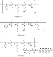
The synthetic route of the common acrylic copolymer (Copolymer a) is shown in Scheme 1. The reaction was conducted in a four-neck round-bottomed flask equipped with a mechanical stirrer, a reflux condenser, an addition funnel and a thermometer. A mixture of butyl acetate and xylene with a weight ratio of 2
:
3 was employed as the solvent. St, MMA, BA, HEMA and AA with a weight ratio of 2
:
2
:
3.5
:
2
:
0.5 were used as the monomers. The amount of initiator BPO accounted for 1 wt% of the whole monomers. At first, 2/5 of the mixed solvent were added into the flask which was then heated to 100 °C under continuous stirring. All of the monomers, 1/2 of the solvent, as well as 9/10 of the BPO solution were added dropwise into the flask for about 3 h. The reaction was maintained at 100 °C for another 2 h at the end of feeding. After that, the residual 1/10 of the solvent and 1/10 of the BPO solution were added dropwise into the flask for about 0.5 h. The polymerization was continued further for 2 h to promote the conversion of the residual monomers. Finally, the reaction mixture was cooled down to room temperature to obtain the common acrylic copolymer (Copolymer a) that was prepared.
 |
| Scheme 1 Synthesis of the common acrylic copolymer (Copolymer a). | |
The first kind of fluorine-containing acrylic copolymer (Copolymer b) was synthesized via an in situ radical polymerization fluorine modification method as shown in Scheme 2. Dodecafluoroheptyl methacrylate (DFHMA) was used as the fluorinated monomer which was copolymerized with styrene and the common hydrocarbon acrylic monomers. The amount of DFHMA was 15 wt% based on the total amount of all monomers, and the ratio among the other monomers was the same as that in Copolymer a. The synthetic process was the same as that for Copolymer a.
 |
| Scheme 2 Synthesis of the fluorine-containing acrylic copolymer (Copolymer b) via an in situ method. | |
The second kind of fluorine-containing acrylic copolymer (Copolymer c) was prepared via a post-polymerization fluorine modification route, as shown in Scheme 3, in which a kind of fluorine-containing monomer (FTDI) was synthesized firstly through the reaction of 1H,1H,2H,2H-perfluoro-1-decanol (FOH) and toluene diisocyanate (TDI). Then, a certain amount of FTDI was added into the solution of Copolymer a in the above solvent mixture of butyl acetate and xylene under continuous stirring at 70 °C. The mole ratio of –NCO to –OH was 1
:
10, wherein the –NCO group came from the FTDI monomer while –OH came from HEMA that copolymerized into Copolymer a. The reaction was conducted for another 1 h after feeding, and Copolymer c was prepared.
 |
| Scheme 3 Synthesis of the fluorine-containing acrylic copolymer via a post-polymerization route. | |
Hexamethylene diisocyanate tripolymer (N3375, Bayer) was employed as a curing agent to react with the remaining hydroxyl groups in the copolymers and form the corresponding acrylic polyurethane coatings. The acrylic copolymers were mixed with stoichiometric N3375 and spin-coated on tin plates. The anticipated acrylic polyurethane coatings were dried at 50 °C for 10 h.
2.3. Environmental experiments
Different imitation experiments including indoor atmospheric environment, hygrothermal environment, thermal resistance at different temperatures, as well as xenon arc aging were employed to investigate the failure behavior of the coatings.
An indoor atmospheric environment with the temperature ranging from 20 °C to 30 °C and the relative humidity ranging from 20% to 40% was employed to test the failure behavior of the coatings.
A chamber with a temperature of 38 °C and relative humidity of 97% was used for the hygrothermal environment.
50 °C, 100 °C and 150 °C were chosen to test the failure behavior of the coatings at different temperatures. The coated samples were put into dry ovens at the set temperature. The relative humidity ranged from 20% to 40%.
Xenon lamp exposure and weathering equipment (Nanjing Wuhe testing equipment Co. Ltd, China) was used to detect the failure behavior of the coatings under an artificial weathering environment. The irradiation intensity was 550 W m2. The black-standard temperature was 65 ± 2 °C and the test chamber temperature was 38 ± 3 °C. An alternating wetting/drying cycle composed of an 18 min wetting time and a 102 min dry period was adopted. The surface of the coated samples in the test chamber was sprayed with de-ionized water during the wetting period, while the relative humidity was maintained at 60% during the dry period.
2.4. Characterization
The chemical structure of the acrylic copolymer was characterized using infrared spectra with a Fourier transform infrared spectrum analyzer (FT-IR, Thermo Nicolet AVATAR, USA) and 19F NMR on a 400 MHz AVANCE III Brüker NMR spectrometer using dimethyl sulfoxide-d6 (CD3SOCD3) as the solvent.
The glass-transition temperature (Tg) of the copolymers was determined using differential scanning calorimetry (DSC, Mettler Toledo, DSC1, Switzerland). The measurement was conducted under a nitrogen atmosphere with the temperature ranging from −20 °C to 200 °C under a heating rate of 10 °C min−1.
The static water contact angle was measured using the sessile drop method using DSA 20 equipment (KRÜSS, Germany) at 23 ± 1 °C. Each sample was tested at three different positions and measured for more than five times to calculate the average value.
The thermostability of the coatings was explored using thermogravimetric analysis (TGA, TA instruments Q5000, USA). The temperature ranged from 35 °C to 500 °C at a heating rate of 10 °C min−1 under a nitrogen atmosphere. The copolymers were cured with stoichiometric N3375 and dried at 50 °C to obtain the corresponding coatings before the test.
An X-ray photoelectron spectrometer (XPS, ESCALAB 250 Xi, Thermo Fisher Scientific, USA) was employed to analyze the elemental composition at the surface of the copolymer films.
3. Results and discussion
3.1. Synthesis of the acrylic copolymers
The chemical structures of the three kinds of copolymers were confirmed using FT-IR and are shown in Fig. 1. It can be observed that all of the copolymers exhibited the characteristic stretching vibration of –OH at 3500 cm−1, the stretching vibration of C–H on the benzene ring from St at 3100 cm−1 to 3000 cm−1, the asymmetrical and symmetrical stretching vibration of –CH3 at 2956 cm−1 and 2875 cm−1 respectively, the stretching vibration of C
O at 1731 cm−1, the stretching vibration of benzene at 1603 cm−1, the asymmetrical and symmetrical deformation vibration of –CH3 at 1454 cm−1 and 1388 cm−1 respectively, as well as the stretching vibration of C–O–C of esters at 1161 cm−1. The characteristic peak of the C
C bond at 1640 cm−1 disappeared, which revealed that there was no residual vinyl monomer. Curve a shows the FT-IR spectrum of the common hydrocarbon acrylic copolymer (Copolymer a). As for the fluorine-containing acrylic copolymer synthesized via the in situ polymerization method (Copolymer b, curve b), the stretching vibration peak of –CF3 appeared at 1243 cm−1. In the FT-IR spectrum of the fluorine-containing copolymer prepared via the post-polymerization route (Copolymer c, curve c), the peak at 1535 cm−1 was assigned to the deformation vibration of N–H from –CO–NH–, while the peaks at 1240 cm−1 and 1151 cm−1 resulted from the characteristic vibration of the C–F bond of the perfluoroalkyl group. In short, it confirmed that two kinds of fluorine-containing acrylic copolymers were prepared following the two different fluorine modification routes.
 |
| Fig. 1 FT-IR spectra of the acrylic copolymers. (a), Copolymer a; (b), Copolymer b; and (c), Copolymer c. | |
The chemical structure of the fluorinated monomers and the fluorine-containing acrylic copolymer was corroborated by 19F NMR as shown in Fig. 2. Fig. 2a shows the 19F NMR spectrum of DFHMA. The chemical shifts ranging from −71 ppm to −76 ppm were assigned to the –CF3 group, while the peaks around 185 ppm and 210 ppm were due to the –CF– group. In the spectrum of FOH (Fig. 2c), the chemical shifts at −81 ppm belonged to the –CF3 group, and the peak at −113 ppm was assigned to the fluorine atoms of –CF2CH2CH2OH, while there also existed characteristic peaks of other –CF2– groups between −121 ppm to −128 ppm. It is clear that Copolymer b and Copolymer c show almost the same peaks as those of DFHMA and FOH, respectively. In addition, the relatively lower amount of fluorine dissolved in dimethyl sulfoxide-d6 resulted in the rough baseline of the spectra of the fluorine-containing acrylic copolymers. As a result, it demonstrated that the fluorine-containing acrylic copolymers were prepared via the modification methods as expected.
 |
| Fig. 2 19F NMR spectra of DFHMA (a), Copolymer b (b), FOH (c), and Copolymer c (d). | |
DSC was employed to test the glass transition temperature (Tg) of the copolymers so as to judge the homogeneity of the copolymerization process.19 One single Tg for a sample reveals that a copolymer rather than a mixture of at least two polymers is obtained during the reaction. Fig. 3 exhibits the DSC curves of the acrylic copolymer and the fluorine-containing copolymers prepared following the above-mentioned different fluorine modification methods. It is apparent that each copolymer exhibited only one Tg, indicating that all of the monomers had been copolymerized statistically into the expected Copolymers b (curve b) and c (curve c). Furthermore, there was no homopolymer generated during the process of either the in situ polymerization or the post-polymerization fluorine modification. Besides, it also revealed that the incorporation of the fluorinated monomers resulted in a higher Tg than the common hydrocarbon one, namely, 43.9 °C and 48.6 °C for the fluorine-containing Copolymers b and c respectively, as compared with 33.3 °C for Copolymer a containing no fluorine.
 |
| Fig. 3 DSC curves of the copolymers. (a) Copolymer a; (b) Copolymer b; and (c) Copolymer c. | |
In conclusion, three kinds of predetermined acrylic copolymers were synthesized via a radical random polymerization route in which two kinds of fluorine-containing acrylic copolymers were prepared via an in situ fluorine modification method and a post-polymerization fluorine modification route, respectively.
3.2. Hydrophobicity failure behavior of the coatings
To explore the hydrophobicity of the coatings in various environments, the three kinds of acrylic copolymers were cured with stoichiometric N3375 in the solvent mixture followed by spin-coating on tin plates to form the corresponding acrylic polyurethane coating films. And the coatings were put into several typical environments. The static water contact angles were tested to investigate the hydrophobicity failure behavior of the coatings.
3.2.1. Indoor atmospheric environment. Fig. 4 shows the water contact angles of the coatings as a function of the exposure time in an indoor atmospheric environment. It can be seen that the three kinds of coatings exhibited a stable hydrophobicity during the test time (500 h). The water contact angle of the common hydrocarbon coating changed little, and was 83.4 ± 1° after a 500 h test, while those of the two kinds of fluorine-containing acrylic polyurethane coatings dropped from the original 96.2 ± 0.7° and 116.9 ± 0.9° to 92.7 ± 0.7° and 112.3 ± 0.4° over 500 h, respectively. Both of the fluorine-containing coatings show better hydrophobicity than the common hydrocarbon one. Moreover, the coating film of Copolymer c exhibits a substantially higher water contact angle than that of the Copolymer b coating, although only a small amount of fluorinated monomer was incorporated within Copolymer c. This might be due to the different fluorine modification route. In the in situ fluorine modification route, DFHMA was copolymerized with the common hydrocarbon monomers. The fluorine segments distributed randomly in the copolymer molecular chains. Although relatively more fluorine content was incorporated, the shorter fluorine chains containing twelve fluorine atoms in each fluoroalkyl side chain as well as the fluorine-containing segments distribution limit at the coating surface determined the coating hydrophobicity. In the post-polymerization fluorine method, the long perfluoroalkyl chains containing seventeen fluorine atoms in each fluoroalkyl chain reacted with the hydroxyl groups of small steric effects. On the other hand, fluorine atoms possess a very low surface free energy and self-aggregation properties, therefore the perfluoroalkyl segments behaved with a preferential orientation toward the film–air surface during the film-forming process.20,21 Thus, as for Copolymer c, the longer perfluoroalkyl segments migrated and were distributed at the coating surface more effectively, resulting in a higher water contact angle when compared with that of Copolymer b. The stable water contact angles revealed that the indoor atmospheric environment had little influence on the coatings.
 |
| Fig. 4 Water contact angles of the coatings in the indoor atmospheric environment. | |
3.2.2. Hygrothermal environment. The water contact angles of the coatings as a function of the test time in a hygrothermal environment are displayed in Fig. 5. Similar trends with the indoor atmospheric environment were observed. The hydrophobicity of the coatings was stable in the hygrothermal environment during the test time (500 h). In fact, although there is a hydrophilic monomer of AA incorporated within the copolymers, the segments of polar polyacrylic acid (PAA) would be oriented toward the film–substrate interface during film-forming since the substrate is also composed of polar material, so that low polar segments were oriented toward the film–air interface which resulted in excellent water resistance. Chemical bonds are stable in the neutral hygrothermal environment at 38 °C over 500 h. In other words, the polymeric units of the copolymers cannot be hydrolyzed under the experimental conditions of the hygrothermal environment. Moreover, hydrophobic fluorinated alkyl groups preferentially migrated to the outmost surface of the film–air interface during film formation. Consequently, the water contact angles of the coatings containing fluorinated alkyl groups are higher than that of the Copolymer a coating. The hygrothermal environment had little influence on the coatings.
 |
| Fig. 5 Water contact angles of the coatings in the hygrothermal environment. | |
3.2.3. Different temperature environments. Different temperature environments were employed to test the failure behavior of the coatings. Table 1 displays the water contact angles of the coatings at different temperatures for 96 h. For the Copolymer a coating, the water contact angle increased with the exposure time at 50 °C and 100 °C, while it increased a little for the first 24 h and then decreased as the exposure time extended further over at least 72 h at 150 °C. As for the fluorine-containing coatings, the hydrophobicity was relatively stable at 50 °C and 100 °C while the contact angles decreased significantly over the test time at 150 °C, especially for the Copolymer c coating. It is clearly seen that the water contact angle dropped dramatically from 117.7° to 85.1° over 24 h at 150 °C, indicating that the hydrophobic Copolymer c film turned to be hydrophilic in reverse. It suggested that the coatings failed slowly in the relatively low temperature environments, while the higher temperature (150 °C) had a larger influence on the coatings.
Table 1 Water contact angles of the coatings under different temperatures
|
Copolymer a coating |
Copolymer b coating |
Copolymer c coating |
50 °C |
100 °C |
150 °C |
50 °C |
100 °C |
150 °C |
50 °C |
100 °C |
150 °C |
0 h |
81.6 |
82.3 |
81.4 |
96.2 |
95.2 |
97.2 |
116.9 |
118.1 |
117.7 |
24 h |
83.2 |
87.2 |
83.9 |
94.3 |
94.1 |
93.8 |
116.3 |
114.4 |
85.1 |
72 h |
85.5 |
88.1 |
81.8 |
94.5 |
96.2 |
92.0 |
115.2 |
112.8 |
80.5 |
96 h |
86.7 |
89.4 |
80.6 |
95.7 |
98.1 |
91.0 |
114.8 |
112.5 |
80.0 |
Fig. 6 exhibits the water contact angles of the coatings at 150 °C for 300 h. The water contact angle of the Copolymer a coating increased a little during the first 24 h, but decreased slowly as the exposure time extended. The water contact angle of the Copolymer b coating also decreased slowly with the test time. Both the Copolymer a coating and Copolymer b coating achieved relatively stable hydrophobicity during the 300 h exposure. As for the Copolymer c coating, however, the water contact angle decreased sharply for the first 24 h. Then the water contact angle was similar to that of the Copolymer a coating, indicating that the fluorine-containing segments might be destroyed.
 |
| Fig. 6 Water contact angles of the coatings at 150 °C. | |
A TGA test was employed to explore the thermostability of the fluorine-containing copolymer coatings and the results are included in Fig. 7. It can be seen that only 0.7 wt% of the Copolymer b coating degraded at 150 °C, while it was 2.3 wt% for the Copolymer c coating. And 10 wt% of the coating degraded at 272.5 °C for the Copolymer b coating but at 206.8 °C for the Copolymer c coating. It is clear that the Copolymer b coating achieved better thermostability than the Copolymer c coating.
 |
| Fig. 7 TGA curves of the Copolymer b and c coatings. | |
The presence of fluorine chains and their migration and degradation behavior can be quantified through surface characterization via XPS. The surface compositions of the coatings before and after the failure experiments at 150 °C with different depth resolution were studied. The maximum depth resolution for XPS is determined by the mean free path of the X-ray photon and is no more than 10 nm. In this characterization, the test depth can be varied by changing the angle between the coating surface in the normal direction and the detector of the instrument. The test depth will decrease when the angle increases. When the angle is 0°, the test depth reaches the maximum value (no more than 10 nm), while the outmost part of the film surface is detected at the maximum angle value of 55° in the employed instrument.
Fig. 8 displays the XPS spectra of the two kinds of fluorine-containing coatings before and after the failure experiment at 150 °C. Table 2 shows the atomic ratio data of the films. It can be seen that there was more fluorine content being detected when the test angle was 55°, suggesting that more fluorine-containing segments migrated toward the film–air interface and distributed on the coating surface. For the Copolymer b coating, the F/C ratio was 0.136 at 0° and 0.160 at 55°. After the environment test at 150 °C, the F/C ratio increased to 0.141 at 0° and 0.182 at 55°, indicating that the fluorine-containing segments were stable and the high temperature was helpful to the migration of the fluorine-containing segments. However, the O/C ratio increased from 0.037 at 0° and 0.026 at 55° to 0.042 at 0° and 0.034 at 55°, suggesting that the oxygen content on the coating surface increased after the environment test at 150 °C for 96 h. This might result in the small decrease of the Copolymer b water contact angle. As for the Copolymer c coating, although less fluorine-containing monomer was incorporated, there was more fluorine content detected on the coating surface. The F/C ratio was 0.620 at 0° and 0.943 at 55° before the failure test, which was much higher than that of the Copolymer b coating. It reveals that the long perfluoroalkyl side chains can migrate more to the coating surface. So the coating achieved better hydrophobicity. However, the fluorine content decreased sharply after the environment test at 150 °C. The F/C ratio decreased to 0.047 at 0° and 0.075 at 55°, resulting in the dramatic decrease of the coating hydrophobicity.
 |
| Fig. 8 XPS spectra of the Copolymer b and Copolymer c coatings before and after the failure experiment at 150 °C: (a), original Copolymer b coating before the test; (b), Copolymer b coating after the failure test; (c), original Copolymer c coating before the test; and (d), Copolymer c coating after the failure test. 0° and 55° were the angles between the film surface of the sample in the normal direction and the detector of the XPS instrument. | |
Table 2 XPS data of the Copolymer b and Copolymer c coatings before and after the failure experiment at 150 °Ca
Atomic% |
Copolymer b coating before test |
Copolymer b coating after test |
Copolymer c coating before test |
Copolymer c coating after test |
0° |
55° |
0° |
55° |
0° |
55° |
0° |
55° |
0° and 55° were the angles between the film surface of the sample in the normal direction and the detector of the XPS instrument. |
C 1s |
71.66 |
71.49 |
69.02 |
67.87 |
51.87 |
45.13 |
73.91 |
73.95 |
N 1s |
2.62 |
1.83 |
2.93 |
2.28 |
5.04 |
4.14 |
4.14 |
2.79 |
O 1s |
16.01 |
15.22 |
18.3 |
17.52 |
10.9 |
8.2 |
18.47 |
17.75 |
F 1s |
9.71 |
11.45 |
9.74 |
12.33 |
32.18 |
42.54 |
3.48 |
5.51 |
Combined with the TGA and the XPS results, it can be inferred that the Copolymer c coating began to degrade at 150 °C, resulting in the sharp decrease in the coating hydrophobicity. This was relevant to the fluorine modification method. In the copolymer coatings prepared via the post-polymerization fluorine modification method (Copolymer c), the fluorine-containing side chains are mostly distributed at the coating surface. When the segments are damaged, the fluorine content at the coating surface will decrease, resulting in the decrease in the coating hydrophobicity. It has been reported that the degradation of the acrylic urethane coating mostly proceeds through a direct or radical induced scission of the urethane linkage.22,23 The fluorinated alkyl side group was incorporated into the copolymer via a linker of toluene diisocyanate (TDI), in which the urethane linkage was produced during the synthesis of Copolymer c. The urethane linkage got ruptured when exposed to heating at 150 °C for 24 h. So the fluorine-containing alkyl chains with an extremely low surface free energy were isolated, resulting in the substantial drop of the water contact angle of Copolymer c. Therefore, the water contact angle of the Copolymer c coating decreased to be almost the same as that of the Copolymer a coating. On the other hand, however, in the fluorine-containing alkyl chain of Copolymer b prepared via the in situ copolymerization route, the fluorine-containing segments were incorporated through the acrylic ester linkage and distributed randomly in the copolymer molecules. The ester bonds are more stable than the urethane linkage at a high temperature, thus the fluorine-containing segments were more difficult to be isolated than Copolymer c. Moreover, the XPS results showed that more fluorine content was detected after the failure test at 150 °C, indicating that the high temperature was helpful to the migration of the low surface energy chains. Even if the coating surface was destroyed due to the breaking of the urethane linkage, the fluorine-containing chains will not get ruptured from the main chains of the coatings. Consequently, the Copolymer b coating exhibited good thermal resistance and remained hydrophobic after exposure to heat at 150 °C for at least 300 h.
3.2.4. Xenon arc aging environment. To explore the failure behavior of the coatings in comprehensive environments, xenon lamp exposure and weathering equipment was used to provide an artificial weathering environment. Fig. 9 displays the water contact angles of the coatings under a xenon arc aging environment. All of the three kinds of coatings failed more quickly compared with the other individual conditions as stated herein above. As in the 150 °C environment, the contact angle of the Copolymer c coating was similar to that of the Copolymer a coating after 50 h exposure. The Copolymer b coating achieved better hydrophobicity than the other two kinds of coating.
 |
| Fig. 9 Water contact angles of the coatings in the xenon arc aging environment. | |
It has been proven that photo irradiation aging plays a more significant role in the degradation of the acrylic urethane coating than the other climatic conditions.22–24 And the photo cleavage of the urethane linkage controls the loss of physical properties of the acrylic urethane coating.24 The xenon test caused more severe damage on the coating surface, including thickness loss.25 Therefore, the hydrophobicity of the three kinds of coatings failed more seriously than that under the other individual conditions. Compared with the 150 °C environment, more severe damage occurred at the coating surface and more components including the fluorine-containing segments in Copolymer b were lost. Therefore, the Copolymer b coating failed to be hydrophilic similar to the other two kinds of coatings shortly after the beginning of the xenon test.
4. Conclusion
Two kinds of fluorine-containing acrylic copolymers were prepared with an in situ radical polymerization fluorine modification method and a post-polymerization fluorine modification route, respectively. And a kind of common acrylic copolymer as a reference was synthesized. The corresponding acrylic polyurethane coatings were prepared using the acrylic copolymers with a stoichiometric isocyanate curing agent. The hydrophobicity failure behaviors of the coatings were explored in different environments, including an indoor atmospheric environment, a hygrothermal environment, different temperature environments, as well as a xenon arc aging environment. FT-IR, 19F NMR and DSC confirmed that the fluorine-containing acrylic copolymers were prepared as expected. The Copolymer b coating prepared with the fluorine-containing acrylic copolymer using the in situ polymerization fluorine modification route exhibited better hydrophobicity in all of the above environments compared with the hydrocarbon acrylic copolymer coating (Copolymer a coating). In common environments including the indoor atmosphere, the hygrothermal and the low temperature conditions, the Copolymer c coating prepared with the fluorine-containing acrylic copolymer via the post-polymerization fluorine method achieved the best hydrophobicity. However, the hydrophobicity of the Copolymer c coating failed quickly in hostile environments, such as high temperature conditions and a xenon arc aging environment. This was due to the different fluorine modification route. The in situ fluorine modification method produced a random copolymer, and the corresponding coating achieved a lower water contact angle than that prepared with the post-polymerization fluorine route. But the coating failed more slowly. The post-polymerization fluorine modification route resulted in a more hydrophobic coating. The fluorine-containing segments distributed at the coating surface, and the fluorine content in the bulk was much lower. However, when the coating was used in hostile environments, the coating surface might be destroyed, which was confirmed by the TGA and XPS characterizations. Therefore, once the fluorine-containing segments decreased, the hydrophobicity of the coating failed quickly.
Acknowledgements
This work was financially supported by the National Natural Science Foundation of China (51173006).
References
- W. Yao, Y. Li and X. Huang, Fluorinated poly(meth)acrylate: Synthesis and properties, Polymer, 2014, 55, 6197–6211 CrossRef CAS.
- D. Han, L. Zhu, Y. Chen, W. Li, X. Wang and L. Ning, Synthesis of fluorinated monomer and formation of hydrophobic surface therefrom, RSC Adv., 2015, 5, 22847–22855 RSC.
- X. Yang, L. Zhu, Y. Zhang, Y. Chen, B. Bao, J. Xu and W. Zhou, Surface properties and self-cleaning ability of the fluorinated acrylate coatings modified with dodecafluoroheptyl methacrylate through two adding ways, Appl. Surf. Sci., 2014, 295, 44–49 CrossRef CAS.
- K. A. Pollack, P. M. Imbesi, J. E. Raymond and K. L. Wooley, Hyperbranched Fluoropolymer-Polydimethylsiloxane-Poly(ethylene glycol) Cross-Linked Terpolymer Networks Designed for Marine and Biomedical Applications: Heterogeneous Nontoxic Antibiofouling Surfaces, ACS Appl. Mater. Interfaces, 2014, 6, 19265–19274 CAS.
- R. A. Iezzi, S. Gaboury and K. Wood, Acrylic-fluoropolymer mixtures and their use in coatings, Prog. Org. Coat., 2000, 40, 55–60 CrossRef CAS.
- W. Xu, Q. F. An, L. F. Hao, D. Zhang and M. Zhang, Synthesis and characterization of self-crosslinking fluorinated polyacrylate soap-free latices with core-shell structure, Appl. Surf. Sci., 2013, 268, 373–380 CrossRef CAS.
- J. Z. Gao, X. M. Wang, Y. X. Wei and W. Yang, Synthesis and characterization of a novel fluorine-containing polymer emulsion with core/shell structure, J. Fluorine Chem., 2006, 127, 282–286 CrossRef CAS.
- Q. H. Zhang, Q. Y. Wang, X. L. Zhan and F. Q. Chen, Synthesis and Performance of Novel Fluorinated Acrylate Polymers: Preparation and Reactivity of Short Perfluoroalkyl Group Containing Monomers, Ind. Eng. Chem. Res., 2014, 53, 8026–8034 CrossRef CAS.
- W. Yang, Y. Chen, D. Han and L. Zhu, Synthesis and characterization of the fluorinated acrylic latex: Effect of fluorine-containing surfactant on properties of the latex film, J. Fluorine Chem., 2013, 149, 8–12 CrossRef CAS.
- D. X. Han, L. Q. Zhu, Y. C. Chen, W. P. Li and L. L. Feng, Synthesis and characterization of acrylic latex: Effects of fluorine and silicon components on properties of the latex copolymers, J. Fluorine Chem., 2013, 156, 38–44 CrossRef CAS.
- S. Ito, S. Kaneko, C. M. Yun, K. Kobayashi and M. Nakagawa, Investigation of Fluorinated (Meth)Acrylate Monomers and Macromonomers Suitable for a Hydroxy-Containing Acrylate Monomer in UV Nanoimprinting, Langmuir, 2014, 30, 7127–7133 CrossRef CAS PubMed.
- C. Benbayer, S. Saidi-Besbes, E. T. de Givenchy, S. Amigoni, F. Guittard and A. Derdour, Copolymerization of novel reactive fluorinated acrylic monomers with styrene: reactivity ratio determination, Colloid Polym. Sci., 2014, 292, 1711–1717 CAS.
- J.-Q. Huang, W.-D. Meng and F.-L. Qing, Synthesis and repellent properties of vinylidene fluoride-containing polyacrylates, J. Fluorine Chem., 2007, 128, 1469–1477 CrossRef CAS.
- R. R. Thomas, D. R. Anton, W. F. Graham, M. J. Darmon, B. B. Sauer, K. M. Stika and D. G. Swartzfager, Preparation and Surface Properties of Acrylic Polymers Containing Fluorinated Monomers, Macromolecules, 1997, 30, 2883–2890 CrossRef CAS.
- V. V. Gite, P. P. Mahulikar and D. G. Hundiwale, Preparation and properties of polyurethane coatings based on acrylic polyols and trimer of isophorone diisocyanate, Prog. Org. Coat., 2010, 68, 307–312 CrossRef CAS.
- Y. F. Zhu, J. P. Xiong, Y. M. Tang and Y. Zuo, EIS study on failure process of two polyurethane composite coatings, Prog. Org. Coat., 2010, 69, 7–11 CrossRef CAS.
- S. Saha, D. Kocaefe, C. Krause and T. Larouche, Effect of titania and zinc oxide particles on acrylic polyurethane coating performance, Prog. Org. Coat., 2011, 70, 170–177 CrossRef CAS.
- Y. He, J. P. Yuan, H. Cao, R. Zhang, Y. C. Jean and T. C. Sandreczki, Characterization of photo-degradation of a polyurethane coating system by electron spin resonance, Prog. Org. Coat., 2001, 42, 75–81 CrossRef CAS.
- K. Landfester, R. Rothe and M. Antonietti, Convenient synthesis of fluorinated latexes and core-shell structures by miniemulsion polymerization, Macromolecules, 2002, 35, 1658–1662 CrossRef CAS.
- W. R. Dreher, A. Singh and M. W. Urban, Effect of perfluoroalkyl chain length on synthesis and film formation of fluorine-containing colloidal dispersions, Macromolecules, 2005, 38, 4666–4672 CrossRef CAS.
- M. Bertolucci, G. Galli and E. Chiellini, Wetting Behavior of Films of New Fluorinated Styrene-Siloxane Block Copolymers, Macromolecules, 2004, 37, 3666–3672 CrossRef CAS.
- F. X. Perrin, M. Irigoyen, E. Aragon and J. L. Vernet, Artificial aging of acrylurethane and alkyd paints: a micro-ATR spectroscopic study, Polym. Degrad. Stab., 2000, 70, 469–475 CrossRef.
- C. Merlatti, F. Perrin, E. Aragon and A. Margaillan, Natural and artificial weathering characteristics of stabilized acrylic–urethane paints, Polym. Degrad. Stab., 2008, 93, 896–903 CrossRef CAS.
- F. Perrin, M. Irigoyen, E. Aragon and J. Vernet, Evaluation of accelerated weathering tests for three paint systems: a comparative study of their aging behaviour, Polym. Degrad. Stab., 2001, 72, 115–124 CrossRef CAS.
- J. Hu, X. Li, J. Gao and Q. Zhao, Ageing behavior of acrylic polyurethane varnish coating in artificial weathering environments, Prog. Org. Coat., 2009, 65, 504–509 CrossRef CAS.
|
This journal is © The Royal Society of Chemistry 2015 |
Click here to see how this site uses Cookies. View our privacy policy here.