
Noble metal@metal oxide semiconductor core@shell nano-architectures as a new platform for gas sensor applications
Prabhakar Rai
*a,
Sanjit Manohar Majhi
b,
Yeon-Tae Yu
b and
Jong-Heun Lee
*cd
aDepartment of Chemical Engineering, Indian Institute of Technology Kanpur, Kanpur 208016, India. E-mail: prkrai@iitk.ac.in
bDivision of Advanced Materials Engineering and Research Centre for Advanced Materials Development, College of Engineering, Chonbuk National University, Jeonju 561-756, Republic of Korea
cDepartment of Materials Science and Engineering, Korea University, Anam-Dong 5-1, Seoul 136-713, South Korea. E-mail: jongheun@korea.ac.kr
dDepartment of Chemical and Materials Engineering, King Abdulaziz University, Jeddah 21589, Saudi Arabia
First published on 28th August 2015
Abstract
Among the complex nanostructures, core@shell nanomaterials are gaining much attention, as the physical properties of the core and shell can be easily and separately tuned. Two materials in the form of core@shell nanostructures combine their individual properties and also bring unique properties in comparison with single-component materials. Recently, the formation of core@shell nanoparticles (NPs) having noble metals (Au, Ag, Pt and Pd) as a core and metal oxides semiconductors (TiO2, SnO2, and Cu2O) as a shell has attracted immense research interest in sensing, photo-catalysis, dye-sensitized solar cells and so on due to tailorability and functionality in the core and shell. Therefore, an overview of the advances in this exciting field of noble metals@metal oxides core@shell NPs has been presented in this feature article. It includes systematic synthesis approaches of noble metal@metal oxide core@shell NPs and their applications in the field of gas sensors, which is based on the literature and our own recent work. The synthesis of core@shell NPs with controllable sizes, compositions, morphologies, structures and functionalities has been presented considering the advantages and the demerits of the process. Applications of these core@shell NPs in the areas of gas sensing and their sensing mechanisms are discussed. The future prospects of such core@shell nanostructures for gas sensing applications are also highlighted.
 Prabhakar Rai | Prabhakar Rai is INSPIRE Faculty in the Department of Chemical Engineering at the Indian Institute of Technology Kanpur, India. Previously, he was Research Professor in the Department of Materials Science and Engineering at Korea University and Assistant Research Professor in the Department of Informatic Electronic Materials Engineering at Chonbuk National University, South Korea. He received his Doctoral degree in Informatic Electronic Materials Engineering, in 2012, at Chonbuk National University, South Korea and M.Sc. degree in Inorganic Chemistry at the University of Allahabad, India. His research is mainly focused on synthesis of nanoscale noble metals@metal oxides core@shell for gas sensor applications. |
 Sanjit Manohar Majhi | Sanjit Manohar Majhi is currently pursuing his doctoral course in the Department of Informatic Electronic Materials Engineering at Chonbuk National University, South Korea. He received his M.Sc. degree in Chemistry, in 2008, at Utkal University, India. He has worked as a researcher from 2009–2012, at the Institute of Minerals and Materials Technology (IMMT), CSIR, Bhubaneswar, India. His research interests include the synthesis of noble metal nanoparticles and metal oxide semiconductors to design core@shell nanostructures for the gas sensor applications. |
 Yeon-Tae Yu | Yeon-Tae Yu is a Professor in the Division of Advanced Materials Engineering at Chonbuk National University. He received his engineering diploma in Department of Metallurgy Engineering in 1988 from Chonbuk National University, South Korea and a Doctoral degree (1993) from Tohoku University, Japan. From 1993 to 2003, he was a Senior Researcher at the Korea Institute of Geoscience and Mineral Resources. In 2004, he moved to the Division of Advanced Materials Engineering of Chonbuk National University as an Assistant Professor. His main research interests are the synthesis of core–shell structure composite nanoparticles and their application for gas sensors. |
 Jong-Heun Lee | Jong-Heun Lee has been a Professor in the Department of Materials Science and Engineering at Korea University since 2003. He received his B.S., M.S. and Ph.D. degrees from Seoul National University in 1987, 1989 and 1993, respectively. Between 1993 and 1999, he developed automotive air-fuel ratio sensors at the Samsung Advanced Institute of Technology. He was a STA fellow at the National Institute for Research in Inorganic Materials (currently NIMS, Japan) from 1999 to 2000 and a Research Professor at Seoul National University from 2000 to 2003. His current research interests include chemical sensors and functional nanostructures. |
1. Introduction
Atmospheric pollution resulting from gaseous pollutants has caused major concerns such as human health issues, acid rain, ozone depletion and the greenhouse effect.1 Thus, gas sensors have become a crucial part of modern life with applications in environmental monitoring and personal safety, which are increasingly being integrated into mass-market applications, for instance in air quality control in buildings and motor vehicles, as well as the more traditional areas of toxic and explosive gas detection. There are various types of detectors available in the market having the same function i.e. to monitor and warn of a dangerous gas level. Among them, chemiresistive metal oxide semiconductor (MOS) sensors are most investigated because of their high sensitivity, small size, low cost and easy maintenance.2 In 1962 Seiyama et al.3 proposed the idea of gas sensing, where adsorption and desorption of gases cause electrical changes, using ZnO thin films. The other commonly used sensor material, SnO2, was proposed as a gas sensor in the same year by Taguchi,4 and since 1968 these sensors have been commercially available through Figaro Engineering.5 Other metal oxides such as n-type (Fe2O3, In2O3, TiO2, and WO3) and p-type (CuO, NiO, Co3O4, and Cr2O3) metal oxides have also been explored as gas sensors.6The receptor and transducer functions are two major key functions involved in gas sensing by chemiresistive MOS devices (Fig. 1).7 The receptor function induces an electronic change on the oxide surface through a gas–solid interface, which results in the recognition of a target gas. The transducer function involves the transduction of the surface phenomenon into an electrical resistance change of the sensor. Thus, the gas sensing mechanism of metal oxides involves change in resistance of the sensor, caused by the chemical adsorption and/or the reaction of test gas molecules on the surface of the sensing materials (Fig. 2). In n-type MOS, oxygen molecules adsorb on the surface and then form the charged chemisorbed oxygen species (O2−, O− or O2−) by capturing free electrons from the conduction band of MOS. It results in decrease in electron density of sensing materials, and therefore electron depletion layers is formed on the surface of sensing materials as shown schematically in Fig. 2a. When the sensors were exposed gaseous atmosphere, such as CO, the gas molecules would react with adsorbed oxygen species on the surface of MOS (2CO(g) + 2O−(ads) ↔ 2CO2(g) + 2e−). As a result, the trapped electrons were released back to the conduction band of MOS, which eventually led to a remarkable decrease of resistance. The serial connection between semiconducting core and resistive shell can be given as an equivalent circuit (Fig. 2b). In p-type MOS, the oxygen adsorption with negative charge electrostatically attracts the holes, which forms hole accumulation layer near the surface (Fig. 2c). The conduction can be explained by the parallel competition between those along semiconducting thin shells and through resistive cores (Fig. 2d). When the sensors were exposed to CO, the electron generated by the reaction between CO and O−(ads) decrease the near-surface hole concentration by electron hole combination reaction, which increase the sensor resistance. These change of resistance in n-type and p-type MOS can be used for the signal of presence of gas through alarm.
 | ||
| Fig. 1 Schematic showing the working principles of gas sensors. | ||
 | ||
| Fig. 2 Schematic showing gas sensing mechanisms of (a and b) n-type MOS and (c and d) p-type MOS. Reprinted with permission from ref. 6. Copyright 2014 Elsevier. | ||
Bare metal oxides are itself active for this function, however this function can be boost to induce a large change in sensitivity by adding additive (noble metals, acidic or basic oxides) to the metal oxide surface.8 Thus, the deposition of a catalyst on metal oxide accelerates the reaction and to increase the sensitivity of MOS gas sensors. The catalyst also influences the selectivity of sensor.9 Therefore, noble metal additives are commonly used as activators or sensitizers to improve/tune the gas selectivity, sensitivity and to lower the operating temperature.10,11 There are two ways in which the catalysts can affect the inter-granular contact region and hence affect the film resistance (Fig. 3). One is the spillover mechanism or chemical sensitization and other is Fermi energy control or electronic sensitization.12 In chemical sensitization, noble metals catalytically activate the dissociation of molecular oxygen, which then adsorb on the metal oxide surface by capturing conductance band electrons. It results in a greater degree of electron withdrawal from the metal oxide than for the bare metal oxide. In electronic sensitization, noble metal acts as an electron acceptor on semiconductor oxide surfaces, which results in increase of the depletion layer.13 Therefore, the change in resistance in noble metals loaded metal oxide is larger as compared with the bare metal oxides, which results in increase in gas response. Thus, noble metal helps in the improvement of sensing performance.
 | ||
| Fig. 3 Schematic showing (a) electronic and (b) chemical sensitization of noble metals. | ||
Traditionally, surface modification of metal oxides involves the deposition of noble metals on metal oxide surface. However, this exercise passivates the effective surface area of metal oxides involved in gas sensing. Also, noble metal NPs are unstable against heating, which results in a loss of catalytic activity mainly because of the increased mobility of the metal NPs on the support at higher temperatures.14 The mobility of metal NPs on oxide support results in the formation of either a shunting layer or an active membrane filter, which effectively obstruct the penetration of the targeting gas into the surface of the gas sensing matrix. The poisoning of noble metal NPs many by many chemicals that contain sulfur (H2S, SO2, and thiols) or phosphorus is another problem of their application.15 Therefore, it was challenging, until the emergence of core@shell structure, to overcome above disadvantages along with improvement in performance and stability of sensor. Recent studies have shown that core@shell structured materials with tailored physical and chemical properties, in both the cores and shells, provide powerful platforms for nanoreactors, drug/gene delivery, lithium-ion batteries, biosensors, photocatalysis, surface-enhanced Raman scattering etc.16–20 The coating is mainly used to modify its optical properties21 as well as passivate the core chemically,22 or as a size selective membrane for catalytic processes at the core surface.23 In case of noble metal@metal oxide core@shell, the formation of Schottky barrier due to large difference between the intrinsic Fermi level of the core and the conduction band energy of the semiconductor shell results in the trapping of mobile electrons in core that diffuse within the shell. Transfer of stored charge to solution phase acceptors will be retarded if the trapping energy Etr = Ef (core) − Ecb (shell) ≫ kT. Therefore, the properties can be modified by changing core or shell materials or the core to shell ratio.24 The coating of shell material increases the overall particle stability and dispersibility of the core particle due to decrease in reactivity and increase in thermal stability. Such a metal@semiconductor particle has shown potential applications in gas sensor as reported by our research group.25 Since then, plenty of research papers have been published by many researchers including us on application of core@shell NPs for gas sensor applications, indicating that the core@shell structured materials are already receiving increasing commercial attention. A large number of synthesis approaches are also available in literature for the preparation of noble metal@metal oxide core@shell structures. A review article on the synthesis and applications of different core@shell NPs are published by Chaudhuri et al.16 Many researchers have also demonstrated the fact that core@shell NPs are widely used in different applications.26–29 However, reviews outlining the utilization of noble metal@metal oxide core@shell NPs in gas sensing have not been available. Therefore, in this feature article we have focused on recent research progress in metal@metal oxides core@shell NPs for gas sensor applications. Based on published works in the literature and some of our own recent works on noble metal@metal oxide core@shell NPs, we have presented a systematic synthesis approaches for the preparation of core@shell NPs and their gas sensing applications in this review. This overview is mainly organized in two sections. In the first section, we present the key synthetic strategies for controlling the size, composition, geometry, structure and functionalization of core@shell NPs by discussing some representative core@shell NPs as examples. In the second section, the applications of core@shell NPs in gas sensing fields are reviewed. Finally, we provide some perspectives on the future developments and directions of the synthesis, characterization and application of core@shell NPs.
2. Synthesis approaches
The formation of noble metal@metal oxides core@shell NPs requires the control of several processes, such as nucleation and growth of the shell material on noble metal seeds. These processes are influenced by a number of factors, such as time, temperature, concentration, synthesis methods, lattice mismatch, interfacial energy, surfactant etc. Typically, the lattice mismatch and lack of chemical interaction between noble metals and metal oxides often results in large interfacial energy between an oxide and a metal. If there is lattice mismatch between two materials then it is hard to synthesize their core@shell configuration. However, ligand/surfactant can be used to tune the interface between two materials. Noble metal@silica core@shell NPs is relatively well-known, however this method has not been extensively applied to other oxide coatings, mainly because of aggregation problems.30 Syntheses of many metal oxides, except for silica, require the use of metal salts as precursors, which could cause aggregation of the seed NPs. However, if the use of metal salts is unavoidable, the use of suitable ligand or surfactant can be the best strategy to form core@shell NPs. The selection of a compatible ligand/surfactant is challenging, and therefore there are only few reports about the synthesis of core@shell NPs metal oxides, although their corresponding pure oxides NPs are common. This is possibly the reason why the core@shell NPs of noble metals with metal oxides is case specific. Therefore, we are going to discuss the synthesis of specific metal@metal oxide core@shell NPs, especially those materials used for gas sensing.2.1 Core@shell NPs
 | ||
| Fig. 4 (a) Schematic illustration of Au@TiO2 nanoreactor formation and size tuning of core catalyst, (b) TEM images of Au@TiO2 core@shell nanoreactors with a central vacant space (prepared in step 3 of (a), and (c)) after enlargement of Au cores (prepared in step 4 of (a)), reprinted with permission from ref. 33 Copyright 2005 Wiley-VCH. | ||
The Au@TiO2 core@shell NPs (500–800 nm) were synthesized in two steps, which involved the deposition of TiO2 shell (200–500 nm) on initially formed Au NPs core (50–150 nm) by hydrothermal method. The ascorbic acid facilitated the formation of well-faceted and large anatase TiO2 crystallites, whereas CTAB developed well-faceted Au cores. Hollow Au@TiO2 core@shell NPs were also formed through Ostwald ripening which involved solid evacuation of central TiO2 crystallites as shown in Fig. 4b. In addition, the size of the Au core (150–250 nm) within the nanoreactor was further tuned through the reduction of gold nutrients in HAuCl4-soaked Au@TiO2 nanoreactors (Fig. 4c), which involved slow inter diffusion between the HAuCl4 inside the nanoreactor and the CTAB/ascorbic acid solution outside the nanoreactor. Our research group has extended this method for the synthesis of M(Au, Ag, Pt)@TiO2 core shell NPs and size and shape of core and shell materials was tuned by controlling the concentration of precursors (Fig. 5a–d).34
 | ||
| Fig. 5 TEM images of the as-prepared core–shell Au@TiO2 core@shell NPs (a) and individual particle image (b), Ag@TiO2 NPs (c), Pt@TiO2 NPs (d), and schematic diagram of the proposed formation process of core–shell Au@TiO2 core@shell NPs with truncated wedge-shaped morphology (e), reprinted with permission from ref. 34. Copyright 2009 American Chemical Society. | ||
In our study, M@TiO2 core@shell NPs with truncated wedge-shaped TiO2 morphology have been formed due to the epitaxially segmented orientation growth of individual TiO2 antenna for single Au@TiO2 core@shell NPs (Fig. 5e). It revealed the epitaxial formation of (101) crystal planes of TiO2 near the Au–TiO2 interface due to matching with exposed Au (111) planes which kept interfacial energy low. It was found that there was a change in growth direction from core to rim region and external region of TiO2 antenna preferentially grew along the [001] direction. The formation of well-defined wedge-like TiO2 shells with externally exposed truncated crystal {004} facets was dependent on the F− ions concentration (produced from hydrolyzed TiF4 precursors). It has been found that the use of microwave resulted in rapid synthesis of Au@TiO2 core@shell NPs at low temperature (at 100 °C for 1 h).35,36 This is because microwave dielectric heating is rapid and it is possible to heat the whole reaction mixture without any temperature gradient. No phase transition in either TiO2 or Au was found and their shape and size was also maintained even after sintering at 900 °C. It is unusual that anatase phase of TiO2 was maintained at 900 °C, because most study shows that anatase phase change to rutile when calcined at >500 °C.37 We have suggested that the inhibition of the transition was related to the stabilization of the anatase phase by the surrounding Au NPs through the formation of Ti–O–Au bonds at the interface.38,39 Interestingly, Au@TiO2 core@shell hollow submicrospheres have been formed when water was replaced by ethanol under hydrothermal condition because ethanol can accelerate both the formation process of amorphous Au@TiO2 solid microspheres and the subsequent Ostwald ripening process.40 As compared to centric core@shell NPs, Seh et al.41 reported the synthesis of eccentric Au@TiO2 core@shell nanostructures via sol–gel method as shown in Fig. 6.
 | ||
| Fig. 6 (a–c) TEM images of (a) 50 nm Au cores, (b) Au@TiO2 (5/25) and (c) Au@TiO2 (5/125) nanostructures. The thinner sides of the TiO2 shells are shown (insets) for (b) and (c). Scale bars of inset = 5 nm. (d) Schematic of shell formation, reprinted with permission from ref. 41 Copyright 2011 Royal Society of Chemistry. | ||
The formation of eccentric core@shell structures involved plane-selective condensation of TiO2 onto citrate-capped Au cores. It has been found that citrate ions bind more strongly to the (111) planes as compared to the (110) or (200) planes of noble metals. Therefore, hydrolyzed titanium alkoxide precursor has easily displaced weakly-bound citrate ions on the (110) and (200) planes as compared to strongly-bound citrate ions on the (111) planes, leading to the eccentric core@shell structure (Fig. 6d). Liu et al.42 reported the synthesis of Au@TiO2 core@shell NPs with controlled shell thickness on having various shape and size of Au NPs core and applied for DSSC. Recently, Goebl et al.43 has reported sol–gel process to coat gold NPs with TiO2 to produce Au@TiO2 core@shell catalyst particles, which can be rendered crystalline via calcinations at high temperatures. Several researchers44–50 tried to synthesize other M@TiO2 core@shell NPs other than Au@TiO2 core@shell NPs. In most cases TiO2 shell layer was porous, and therefore these materials would be very useful platforms for sensing and catalytic applications.34–36,41
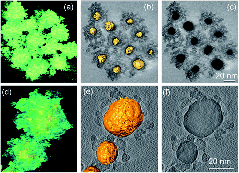 | ||
| Fig. 7 3D reconstructed volumes and sliced images of Au@SnO2 core@shell NPs prepared by (a)–(c) precipitation method and (d)–(e) microwave-assisted hydrothermal method. Reprinted with permission from ref. 53. Copyright 2012 Elsevier. | ||
However, it was difficult to control the shell thickness in these methods and free SnO2 NPs were formed with increasing stannate concentration. The thickness and density of the oxide shell Au@SnO2 core@shell NPs was controlled by Tripathy et al.54 using sonochemical method by adjusting sodium stannate concentration. Several other researchers have also attempted to synthesize Au@SnO2 core@shell NPs via different techniques. Yu et al.55 synthesized Au@SnO2 by intermetallics-based dry oxidation method, where SnO2 shell was grown directly from one component of the intermetallics (AuS) by selective oxidation. Au NPs with a mean size of ca. 15 nm were uniformly encapsulated by the SnO2 shell. The thickness of the shell was 6–7 nm, and the final size of the Au@SnO2 NPs was in accordance with the AuSn NPs. Colloidal technique has been reported by Patra and co-workers56 to synthesize Au@SnO2 core@shell NPs. Meanwhile, core@shell NPs of SnO2 with other noble metals except gold have not achieved similar success and in most cases well defined core@shell NPs were not formed.57–60
 | ||
| Fig. 8 SEM images showing the selective growth of different numbers of ZnO nanorods on the {111} facets of Ag truncated nanocubes. The corresponding geometrical models of the heterogeneous nanostructures are presented. The yellow and cyan color in schematic of Ag crystal represent the {111} and {100} facets of Ag, respectively. The green color represent the facets of the ZnO nanorods. Reprinted with permission from ref. 63. Copyright 2009 American Chemical Society. | ||
Several researchers65–67 have also attempted to prepare well defined core–shell Ag@ZnO NPs. However, these were preliminary studies without in-detailed information on the formation mechanism of core@shell NPs. More recently, Sun et al.68 successfully synthesized metal@ZnO core@shell NPs with well-defined morphology and presented a detailed growth mechanism (Fig. 9).
 | ||
| Fig. 9 TEM images and photographs of metal@ZnO NPs that were synthesized from different noble metal cores: citrate-stabilized NPs, including (a) Au nanospheres (dAu = 15 nm); (b) Ag nanospheres (dAg = 60 nm); and (c) Pt nanospheres (dPt = 40 nm); and PVP-stabilized NPs, including (d) Pd nanospheres (dPd = 20 nm); (e) Ag nanocubes (dAg = 150 nm); and (f) AgNWs (dAgNW = 120 nm, lAgNW = 3–5 μm). Insets show magnified views of typical NPs. Scale bar: 200 nm. Reprinted with permission from ref. 68. Copyright 2013 American Chemical Society. | ||
It has been found that the polyvinylpyrrolidone (PVP) and 4-mercaptobenzoic acid used in the synthesis of Au@ZnO played an important role. They found that 4-mercaptobenzoic acid can reduce the Au–ZnO interfacial energy.69 However, in the absence of PVP, ZnO did not interact well with the hydrophobic ligands on the Au surface indicating that the amphiphilicity of PVP was essential in the ZnO encapsulation when hydrophobic ligands were used. This method was further extended to include Fe3O4, MnO, Co2O3, TiO2, Eu2O3, Tb2O3, Gd2O3, β-Ni(OH)2, ZnS, and CdS as the shell materials, demonstrating the versatile nature of coating (Fig. 10).
 | ||
| Fig. 10 TEM images of the Au@oxide NPs (dAu = 40 nm) with different kinds of oxide shells: (a) Au@Fe3O4, (b) Au@MnO, (c) Au@Co2O3, (d) Au@TiO2, (e) Au@Eu2O3, (f) Au@Tb2O3, (g) Au@Gd2O3, (h) Au@Ni(OH)2, and (i) (Au@Ni(OH)2)@ZnO. Insets show magnified views of typical NPs. Scale bar: 200 nm. Reprinted with permission from ref. 68. Copyright 2013 American Chemical Society. | ||
Similar strategy was applied by Yang et al.70 to synthesize metal@ZnO core@shell NPs using ascorbic acid to induce deposition of ZnO on various shaped and structured cationic-surfactant-capped NP surfaces, where metal was Au, Ag, Pt, Pd and their bimetallics, such as Au@Ag, Pd@Au, Pd@Pt, Au@Pt etc. This strategy can be directly used to coat CTAB or CTAC metal NPs prepared in water phase (Fig. 11a–x). Oil-soluble NPs prepared in organic solvent can also serve as effective seeds for preparing M@ZnO NPs after they are transferred to water with CTAB as shown in Fig. 11z. It has been reported that ascorbic acid and CTAB act as templates, which block the continuous growth of ZnO, and therefore large sized single crystalline products cannot form. Three dimensional Au@ZnO core@shell NPs were also synthesized having ZnO nanorods grown radially on Au NPs cores.71,72 Many more reports on the synthesis of Au@ZnO core@shell NPs has been published in recent times.73,74
 | ||
| Fig. 11 The typical TEM and HAADF images of seeds and corresponding M@ZnO NPs: (A and B) 15 nm Ag NPs and Ag@ZnO; (C and D) 50 nm Au NPs and Au@ZnO; (E and F) Pd NPs and Pd@ZnO; (G and H) Pt nanodendrites and Pt@ZnO; (I and J) Au@Ag NPs and Au@Ag@ZnO; (K and L) Pd@Au NPs and Pd@Au@ZnO; (M and N) Pd@Pt NPs and Pd@Pt@ZnO; (O and P) Au@Pt NPs and Au@Pt@ZnO; (Q and R) hollow Au/Ag nanostructures and Au/Ag@ZnO; (S and T) Au@Ag nanorods and Au@Ag@ZnO; (U and V) short Au nanorods and Au@ZnO; (W and X) dogbone-like Au nanorods and Au@ZnO; (Y) the coating of hydrophobic NPs with ZnO. Reprinted with permission from ref. 70. Copyright 2013 Royal Society of Chemistry. | ||
 | ||
| Fig. 12 (a) SEM image, (b, c and d) TEM images and (e) a schematic illustration of the formation of the Ag@Fe3O4 core@shell nanospheres. Reprinted with permission from ref. 79. Copyright 2012 Royal Society of Chemistry. | ||
The Ag cores (50 nm) were irregular in shape and were well wrapped by the Fe3O4 shell (70 nm). It was demonstrated that the Ag core was produced at the beginning of the reaction followed by the deposition of Fe3O4 shell (Fig. 12e). During the ripening, the amorphous Fe3O4 transformed to polyhedron-like nanocrystals and thus the mesopores were produced due to the loose packing of the Fe3O4 nanocrystals. Similarly, Zhang et al.80 demonstrated a convenient one-step solvothermal strategy of Ag@Fe3O4 core@shell nanostructures. It has been demonstrated that Ag NPs were formed first, which have served as the in situ seeds for the successive catalytic reduction, leading to the growth of outer Fe3O4 shells. Since the standard potential of Ag+/Ag0 is higher than that of Fe3+/Fe2+, the reduction rate of Ag+ to Ag0 was faster than that of Fe3+ to Fe2+and Ag cores are initially formed. Furthermore, this method was also employed to prepare Au@Fe3O4 core@shell nanostructures simply by replacing AgNO3 with HAuCl4. Recently, Knobel and his co-workers81 reported the synthesis of brick-like Ag@Fe3O4 core@shell NPs using single-step thermal decomposition of iron, with the presence of silver seeds formed in the same reaction mixture (Fig. 13). The role of the temperature pause was essentially to divide the Ag and the iron oxide production inside a single reaction, avoiding the necessity of manipulation and the time consuming gap between steps (Fig. 13a). However, thermal stability of these core@shell NPs in air has not been examined in these literatures. It is well known that heating of Fe3O4 in air results in α-Fe2O3, therefore, it is possible to convert these M@Fe3O4 core@shell NPs into their corresponding Fe2O3 core@shell NPs.82 Synthesis of core@shell metal@Fe2O3 NPs was also reported by many researchers, however they are not of our interest, as they are specific case and their formation mechanism has not been discussed in detail.83–88
 | ||
| Fig. 13 (a) Temperature profile of the temperature-paused single-step thermal decomposition synthesis. Boxes sketch the expected predominant structures for each time zone. Typically, both waiting times are 120 minutes. Images: TEM images of BLNs obtained following the temperature-paused single-step protocol. Ag corresponds to the dark contrast, while lighter particles correspond to magnetite. Plain magnetite nanoparticles which are formed are also shown in (c). (a) (b) and (d) are different amplifications of BLNs in order to understand the structure. Reprinted with permission from ref. 81. Copyright 2014 Nature. | ||
Yolk@shell metal@iron oxide has also been reported by several researchers. For example, gold (core)/iron oxide (hollow shell) NPs were prepared by Shevchenko et al.89 The addition of oleic acid to the reaction mixture changes the morphology of the gold@iron oxide core@hollow-shell NPs, leading to more uniform shells formed around the gold cores. Wei et al.90 synthesized a uniform multifunctional nanostructure, Ag@Fe2O3 yolk@shell NPs by the Kirkendall effect. A facile approach to synthesize rattle type magnetic nanocomposite with a permeable Fe3O4 shell and noble metallic core was reported by Xuan et al.91 The formation mechanism involved in situ reduction of noble metal NPs fallowed by transformation of Fe3O4 hollow spheres from Fe-complex precursor through an Ostwald ripening process as shown in Fig. 14a.
 | ||
| Fig. 14 (a) Schematic illustration of the formation of the rattle type nanostructure and (b) TEM images of the rattle type Pd@Fe3O4 nanocomposites. Reprinted with permission from ref. 91. Copyright 2011 Royal Society of Chemistry. | ||
 | ||
| Fig. 15 SEM, TEM, cross-sectional TEM and HRTEM images (red square regions) of the Au@Cu2O core@shell nanostructures. (a–c) Cuboctahedral heterostructures made from octahedral Au NP cores. (d–f) Truncated stellated icosahedra formed from highly faceted Au NP cores. (g–i) Cu2O shells with pentagonal prism shape from 5-fold-twinned Au nanorods as templates. (j–l) Thick truncated triangular Cu2O plates formed from triangular and truncated triangular Au plates as templates. The Cu2O plates are slightly concave, with thinner central triangular portions. The (111) planes of Cu2O grow epitaxially on the facets of Au, while the (200) planes of Cu2O deposit over the {200} facets of Au to form the interfaces. Reprinted with permission from ref. 93. Copyright 2009 American Chemical Society. | ||
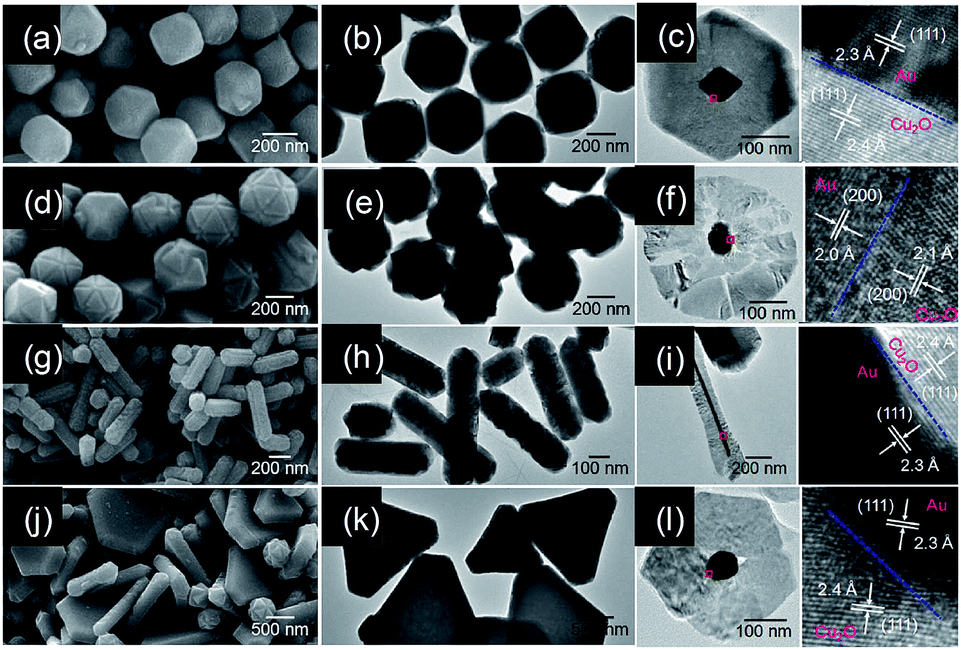
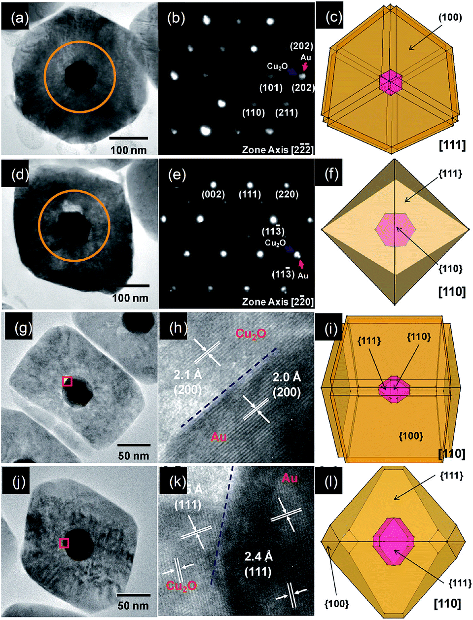
It has been found that the Au NPs cores have guided the growth of Cu2O shells with morphological and orientation control. It has been suggested that the (111) planes of Cu2O were found to grow epitaxially on the {111} facets of gold for most of the cases examined, while the (200) planes of Cu2O can grow over the {200} facets of gold to form the interfaces. Interestingly, the lattice mismatch between the (111) planes of Au and the (111) planes of Cu2O is about 4.5%, whereas 4.7% between the (200) planes of Au and the (200) planes of Cu2O. Their analysis suggested that despite the presence of a significant mismatch between Au and Cu2O lattice planes, Au@Cu2O core@shell heterostructures with excellent interfacial epitaxial growth can still be prepared. In similar study, they have used rhombic dodecahedral and edge- and corner truncated gold nanocrystals with entirely or significant {110} facets as structure-directing cores for the fabrication of Au@Cu2O core@shell heterostructures with systematic shape evolution (Fig. 16).94 By varying the volume of reductant added, shell morphology was systematically tuned from face-raised cubic to cuboctahedral and octahedral structures. They found that the gold cores have an exact orientation relationship with the Cu2O shells. The {100}, {110}, and {111} faces of the gold nanocrystal cores were parallel to the corresponding faces of the Cu2O shells.
 | ||
| Fig. 16 (a and c) Cross-sectional TEM images of the heterostructures viewed along the [111] and [110] directions and (b and d) SAED patterns of the circled regions in panels a & c of a single Au@Cu2O core@shell face-raised cube and octahedron using rhombic dodecahedral gold nanocrystal cores. (g and j) Cross-sectional TEM images of the heterostructures viewed along the [110] direction; (h and k) interfacial HRTEM images of the red square regions in panels g & j of a single Au@Cu2O core@shell face-raised cube and truncated octahedron using edge- and corner-truncated octahedral gold nanocrystal cores; (c, f, i and l) the corresponding drawings. Reprinted with permission from ref. 94. Copyright 2011 American Chemical Society. | ||
Zhang et al.96 have developed a robust wet chemical approach for the highly controllable fabrication of Au@Cu2O hybrid core@shell and rattle-like yolk@shell NPs. Since then many researchers including our research group have synthesized metal@Cu2O core@shell NPs for various applications, such as photocatalysis, gas sensors etc.97–107 In our recent study,106 Au@Cu2O core@shell NPs were synthesized by simple solution route and applied for CO sensing applications. Here, Au nanorods (10–15 nm width and 40–60 nm length) were used as core and 30–60 nm Cu2O shell layer were deposited to form bricks and spherical shape Au@Cu2O core@shell NPs. The morphology of Au@Cu2O core@shell NPs was tuned from brick to spherical shape by controlling the pH of the solution. It suggests that core materials are not only the structure directing agent, but synthesis parameters also play an important role. Recently, a novel class of one-dimensional Ag@Cu2O core@shell heteronanowires has been synthesized at room temperature for photocatalysis application by Xiong et al.108
![[double bond, length as m-dash]](https://www.rsc.org/images/entities/char_e001.gif) O groups) present on the carbon surface when these carbonaceous spheres were dispersed in aqueous indium trichloride solutions. Accompany with the following calcination process in air, the carbonaceous templates shrank gradually while the surface layers containing In3+ were condensed to accumulate sufficient mechanical strength to keep the well-defined configuration of spherical NPs (Fig. 17a). After the carbonaceous templates were removed completely, highly crystalline In2O3 spheres with closely packed NPs were finally obtained (Fig. 17c). The proposed growth mechanism suggests that the core@shell NPs are formed neither by epitaxial growth of In2O3 nor by surfactant stabilization of In2O3 on Au NPs, but it is simply a kind of physical adsorption.
O groups) present on the carbon surface when these carbonaceous spheres were dispersed in aqueous indium trichloride solutions. Accompany with the following calcination process in air, the carbonaceous templates shrank gradually while the surface layers containing In3+ were condensed to accumulate sufficient mechanical strength to keep the well-defined configuration of spherical NPs (Fig. 17a). After the carbonaceous templates were removed completely, highly crystalline In2O3 spheres with closely packed NPs were finally obtained (Fig. 17c). The proposed growth mechanism suggests that the core@shell NPs are formed neither by epitaxial growth of In2O3 nor by surfactant stabilization of In2O3 on Au NPs, but it is simply a kind of physical adsorption.
 | ||
| Fig. 17 (a) Schematic formation process of the Au@In2O3 core@shell structures. TEM images of (b) Au@C core@shell and (c) Au@In2O3 core@shell NPs. Reprinted with permission from ref. 111. Copyright 2014 Royal Society of Chemistry. | ||
Au NP core with the diameter of about 17 nm is surrounded with a CeO2 shell, which was composed of NPs with about 8–10 nm diameter as shown in Fig. 18. The formation mechanism of Au@CeO2 core@shell submicrospheres suggests that Au3+ ions were reduced to Au0 by glucose under the hydrothermal condition, which was followed by carbonization of glucose around Au NPs through the dehydration–condensation reaction. The decomposition of urea resulted in the release of OH− ions, which has promoted the adsorption of Ce3+ ions with the functional groups of carbon. The calcination of as prepared Au@C@CeO2 submicrospheres resulted into the burning of carbon and simultaneous oxidation of Ce3+ ions in the CeO2, which leaded in to the formation of Au@CeO2 core@shell NPs. It was found that the sizes of Au NP cores were maintained around 17 nm during the calcination process, though the overall sizes of the submicrospheres considerably decreased. This result demonstrates the excellent physical confinement of CeO2 shells, which effectively prevents possible sintering, migration and growth of Au NP cores. Hollow core@shell NPs have also been synthesized by hydrothermal119 as well as template method.120
 | ||
| Fig. 18 (a) SEM image of Au@CeO2 submicrospheres. The inset is the corresponding size histogram. (b) TEM image of Au@CeO2 submicrospheres. The inset is the magnified TEM image. (c) HAADF-STEM mapping image of one submicrosphere. (d) TEM image of the CeO2 shell of the submicrospheres. (e) HRTEM image of the submicrospheres. The inset is the selected area electron diffraction (SAED) image, indicating the polycrystalline nature of the CeO2 shell. (f) XRD pattern of the submicrospheres. Reprinted with permission from ref. 118. Copyright 2014 Royal Society of Chemistry. | ||
2.2 Yolk@shell NPs
The yolk@shell nanostructures represent a special class of core@shell structures with a distinctive core@void@shell configuration. The use of template-based routes is an effective approach for the formation of hollow capsules of functional materials. Therefore, a detailed description of the synthesis methodologies of yolk@shell NPs based on template routes is provided in this section. | ||
| Fig. 19 (a) Synthetic route to Au@SnO2 yolk@shell nanospheres. TEM images of the products obtained after each step: (b) Au NPs; (c) Au@SiO2 core–shell structures; (d) Au@SiO2@SnO2 core@shell@shell structures; (e) Au@SnO2 yolk@shell structures. Reprinted with permission from ref. 128. Copyright 2013 Royal Society of Chemistry. | ||
This versatile method has been used successfully to synthesize various yolk@shell NPs, though the synthesis of yolk@shell structures with the required size, shape, and surface properties is still difficult. Other disadvantages are the partial etching and grain growth. Furthermore, the high production cost of the SiO2 template method also limits the use of this method at small-scale.
 | ||
| Fig. 20 (a) Schematic presentation of the formation mechanism Au@NiO yolk@shell NPs. TEM images of (b) Au@C core@shell and (c) Au@NiO yolk@shell NPs. Reprinted with permission from ref. 133. Copyright 2014 Royal Society of Chemistry. | ||
Despite all the successes in this field, the synthesis of noble metal@metal oxide core@shell NPs often requires multi-step approaches. Thus, the lack of a general method for the synthesis of high quality core@shell NPs with controllable sizes, compositions, shapes, and nano-architectures at a low cost is highly required. The lattice mismatch between metal and metal oxide should be carefully considered to develop a generalized method for the synthesis of variety of core@shell NPs. Synthesis of core@shell NPs with multiple cores is another challenge. The yolk@shell NPs with hollow space between core particles and shells can also be used to harvest unique advantages over traditional core@shell NPs. Therefore, it is required to develop a facile synthesis method for core@shell or yolk@shell with control in functionality, size, shape and structure in order to achieve new or enhanced properties.
3. Gas sensing applications of core@shell nanostructures
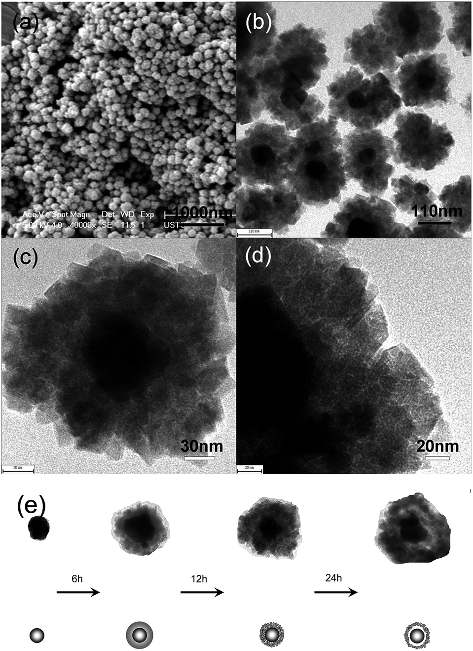
Herein, we will highlight some existing and potential applications of core@shell NPs, with special focus on their applications in gas sensor. The use of core@shell NPs in gas sensing has been initiated by our research group in our knowledge.25 The gas sensing properties of CO (1000–200 ppm) gas was investigated, which showed higher response (Rs = (Ra − Rg)/Ra) for core@shell NPs compared to bare SnO2 NPs. The higher response of the Au@SnO2 core@shell NPs was related to the electronic as well as chemical sensitization of Au NPs. Further study of microstructural property of Au@SnO2 core@shell NPs showed that high porosity within SnO2 shell layers increased the accessibilities of Au NP to the CO gas molecules and resulted in high CO responses.53 Since, gas sensor operation involves high temperature, thermal stability of core@shell NPs for high temperature sensing was also examined by our research group using Au@TiO2 core@shell NPs.36 It is well known that the anatase phase of TiO2 is highly unstable and start to transform in rutile phase at high temperature, mostly above 500 °C. This phase transition may induce a drift in response at high sensor operating temperatures. However, there was no phase transition from anatase to rutile even after sintering of these Au@TiO2 core@shell NPs at 900 °C. It indicates the thermal stability of core@shell morphology and sensor at elevated temperature. Furthermore, the response (Rs = Ra/Rg) of Au@TiO2 core@shell NPs was higher as compared to pure TiO2 at the entire sensing temperatures and concentrations of CO (1000–200 ppm). Since then, several researchers have used core@shell NPs for gas sensor applications.54–60 Wu et al.58 have investigated the sensing mechanism of Ag@SnO2 core@shell NPs for ethanol (200 ppm) by comparing its gas sensing performance with bare SnO2 and 1 wt% Ag/SnO2 nanocomposites. The sensor response (Rs = Ra/Rg) of bare SnO2 was 1.54, and the response and recovery times were 54 s and 85 s, respectively. For 1 wt% Ag/SnO2 nanocomposites, the sensor response, response and recovery times were 1.24, 52 s and 53 s, respectively. It was found that the Ag@SnO2 core@shell NPs had a better sensor response of 2.24 and the shorter response and recovery times of 34 s and 68 s, respectively. The lower response of Ag/SnO2 nanocomposite than that of bare SnO2 indicates that the silver might block some active sensing sites on the surface of SnO2. The high response of Ag@SnO2 core@shell was related to surface area, where the specific surface area of the core@shell structure was higher than that of the bulk material.To investigate the sensing mechanism they have calculated the adsorption of the C2H5OH molecule on Ag@SnO2 core@shell NPs. It has been found that the adsorption energy of C2H5OH on Ag@SnO2 core@shell NPs is smaller than SnO2, which is closer to van der Waals' force as shown in Fig. 21a. Furthermore, the magnitude of the exothermic adsorption energy decreases with increasing adsorbed molecules. For example, the distance between an ethanol molecule and the surface of Ag@SnO2 core@shell NPs was 0.2786 nm when one to ten ethanol molecules were adsorbed (Fig. 21b). This distance was similar to the distance required for a van der Waals' interaction. This resulted in faster desorption of C2H5OH for Ag@SnO2 core@shell NPs as compared to SnO2, which was responsible for faster recovery time. The faster response of Ag@SnO2 core@shell NPs was explained on the basis of two ways transfer of electron in Ag@SnO2 core@shell NPs as compared to one way transfer in SnO2 which has resulted in lower resistance of Ag@SnO2 core@shell NPs as compared to SnO2 (Fig. 21c). Recently, similar result was reported by Chung et al.,136 where Au@SnO2 core@shell structures were synthesized by precipitation method and applied for formaldehyde sensing at room temperature. The response (S = RHCHO/Rair) of Au@SnO2 core shell NPs (2.9) to 50 ppm HCHO was higher compared to Au/SnO2 composite (2.4) and bare SnO2 NPs (1.0). Au@SnO2 core@shell also showed selectivity for formaldehyde compared to methanol, ethanol, and NO2. Similar result has been reported by other researchers109–111,137,138 using different metal oxides for core@shell NPs, where core@shell NPs has shown better performance in terms of high response, fast response and recovery and low operating temperature as compared to bare and noble metal deposited metal oxide NPs.
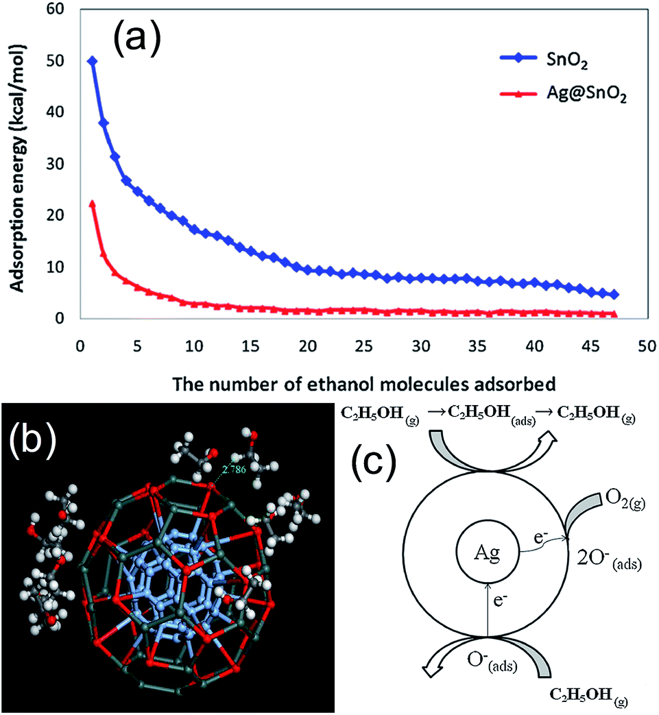 | ||
| Fig. 21 (a) Exothermic energy of adsorption of each ethanol molecule on SnO2 and Ag@SnO2 surface, (b) simulation of adsorption of ten ethanol (C2H5OH) molecules on Ag@SnO2 [white circles represent hydrogen atoms; black circles represent carbon atoms; red circles represent oxygen atoms; blue circles represent silver atoms; dark green circles represent tin atoms], and (c) mechanism of sensing of C2H5OH by Ag@SnO2. Reprinted with permission from ref. 58, Copyright 2013 Elsevier. | ||
More recently Xu et al.110 have designed and fabricated a localized surface plasmon enhanced chemical sensor based on Agx@(2D-WO3) core@shell NPs. They have synthesized pure WO3, Agx–WO3 mixture, and Agx@(2D-WO3) core@shell NPs and investigated their sensing properties (Fig. 22a–d). The combination of the Ag core and the 2D layered structure of WO3 shell have enhanced sensor performance due to effective localized surface plasmon generation and propagation. The sensor response (Rs = Ra/Rg) was increased from 44 for pure WO3 and 52 for Agx–WO3 mixture to 154 for the Agx@(2D-WO3) core@shell structure towards 500 ppm alcohol. Response and recovery time are also shortened considerably from 3 and 15 s for pure WO3, 12 and 7 s for the Agx–WO3 mixture to 2 and 4 s for the Agx@(2D-WO3) core@shell nanostructure. Moreover, optimum sensor working temperature lowered from 370 °C to 340 °C. Thus, the sensors made of Agx@(2D-WO3) core@shell NPs show significantly better performance comparing to those from pure WO3 and Agx–WO3 mixture. The sensing mechanism was explained on the basis of Schottky barrier formation between n-type WO3 and Ag NPs. The electrons were transferred from WO3 to Ag in the Agx@(2D-WO3) core@shell nanostructure due to higher work function of Ag NPs, which resulted in wider depletion zone formation in Agx@(2D-WO3) core@shell as compared to pure WO3 NPs. Therefore, the response of Agx@(2D-WO3) core@shell was higher as compared to pure WO3 NPs. The lower response of Ag–WO3 mixture as compared to Agx@(2D-WO3) core@shell was explained on the basis of poor Schottky junction formation resulted from relatively long distance between Ag and WO3 NPs and/or the agglomeration of Ag and WO3 NPs, as WO3 powder and Ag NPs were prepared separately before being mixed together. Furthermore, the effect of surface plasmon resonance of Ag NPs on gas sensing has been investigated by light irradiation. They have measured sensor response as a function of illumination wavelength using LEDs emitting at 405 nm, 530 nm and 680 nm as shown in Fig. 22e. It has been found that the response of Agx@(2D-WO3) sensor was increased after light irradiation especially at blue wavelength where it resonates with the absorption of Ag NPs. The sensor response increases by 188% (from 217 to 408), when irradiated using a 405 nm blue LED, whereas only 10% improvement was observed for 530 nm and 680 nm LEDs irradiation. Furthermore, normalized response for sensors based on Ag(25 nm)@(2D-WO3) core@shell, Agx–WO3 mixture and pure WO3, were measured at their respective optimum sensor working temperature for 100 ppm alcohol vapor under different illumination ranging from darkness to, 1 sun intensity (Fig. 22f). They found that with increasing light intensity from darkness to 87 mW cm−2 resulted in 40% and 60% increase in response of the pure WO3 and Agx–WO3 mixture, respectively. However, response of Ag(25 nm)@(2D-WO3) core@shell NPs increased 308% comparing to its measurement in darkness, which shows its much greater dependence on light intensity. Therefore, the highest increase in response at 405 nm wavelengths clearly suggests that the sensor enhancement is due to the surface plasmon effect of Ag NPs, as surface plasmon wavelength for 25 nm Ag NPs is closer to 405 nm.139 Raman study also confirmed this phenomenon as Raman intensity of Agx@(2D-WO3) core@shell NPs was enhanced by 20 times, which is consistent with enhance in sensor performance. Thus, it was proved that localized surface plasmon resonance is a major factor for the enhanced sensor response. This study clearly demonstrates that surface plasmon effect of core metal NPs can be effectively used to boost sensor performance of a core@shell nanostructure and well-defined nanostructures of the shell component are also important to design gas sensors.
 | ||
| Fig. 22 (a–d) TEM images of Agx@(2D-WO3) core@shell NPs (insets in a and b show the FESEM image of the corresponding Ag NPs with expected diameters). Sensor response under illumination. (e) Sensor response of Ag(25 nm)@(2D-WO3) core@shell NPs at different wavelength of LED irradiation. (f) Normalized sensor response for Ag(25 nm)@(2D-WO3) CSNS, Agx–WO3 mixture and pure WO3 vs. light illumination intensity using a xenon arc light source (150 W) attenuated using neutral density filters. (g) An illustration of the Schottky junction and LSP enhanced mechanism in Agx@(2D-WO3) based sensors. Reprinted with permission from ref. 110. Copyright 2014 Nature. | ||
However, these studies are focused on n-type metal oxide as shell materials and metal@p-type metal oxide core@shell NPs has not been used for sensing for long time. Recently, our research group and other researchers105–107 have reported the use of noble metal@p-type metal oxide core@shell NPs for gas sensing application. Similar to n-type core@shell NPs, p-type core@shell NPs also shows enhanced sensing performance in terms of response, response time, recovery time and lowering of working temperature. For example, Lin et al.107 has synthesized M(Au, Ag, Pd)@Cu2O core@shell NPs and investigated the role of noble metals on sensing performance of Cu2O as shown in Fig. 23a–d. The sensor response (Rs = Rg/Ra) to 200 ppm of CO was estimated to be 1.66, 2.61, 1.80, and 2.06 for pure Cu2O, Au@Cu2O, Ag@Cu2O and Pd@Cu2O nanocrystals, respectively (Fig. 23e). It has been found that the extent of resistance change for CO detection was different in metal@Cu2O nanocrystals due to different electron trapping capability of Au, Ag and Pd NPs. The high work function of Au (5.1 eV) and Pd (5.3 eV) as compared to Cu2O (4.8 eV) resulted in transfer of conduction band electrons of Cu2O to metal, leaving abundant holes in Cu2O to increase the hole mobility. For Ag@Cu2O nanocrystals, the lower work function of Ag (4.3 eV) has induced electron transfer from Ag to Cu2O, which formed Schottky barrier at the interface as the thermodynamic equilibrium was reached. Thus, the extent of resistance change upon the exposure to CO was enlarged for metal@Cu2O nanocrystals as compared to pure Cu2O, which resulted in increase in response.
 | ||
| Fig. 23 TEM, HRTEM images and EDS data of (a) pure Cu2O, (b) Au–Cu2O, (c) Ag–Cu2O and (d) Pd–Cu2O nanocrystals; (e) responses of pure Cu2O and metal–Cu2O nanocrystals to 200 ppm of CO recorded at 200 °C. Reprinted with permission from ref. 107. Copyright 2014 Elsevier. | ||
Thus, noble metal@metal oxide core@shell NPs have proved their potential for high performance gas sensor application as compared to noble metal decorated metal oxide or pure metal oxide NP. In most studies of n-type MOS gas sensors, the improvement in sensor response was explained by electronic sensitization (increase in depth of depletion layer formation due to Schottky barrier formation) and/or chemical sensitization of noble metals. In electronic sensitization, it has been explained that the increase in air resistance (Ra) of n-type metal oxide due to decrease in carrier density after Schottky barrier formation results in increase in sensor response (Rs) as it is examined either by Ra/Rg or (Ra − Rg)/Ra for reducing gases.36,111,138 Similarly, in p-type metal oxide, the response (Rs) is measured either by Rg/Ra or (Rg − Ra)/Ra for reducing gases, and therefore the low Ra value for metal@p-type metal oxide due to increase in hole mobility after Schottky barrier formation results in improvement in response.105–107 However, this simple explanation is not always acceptable60,107 because the contribution of chemiresistive variation can become relatively more dominant also in p-type oxide semiconductor materials with lower charge carrier concentration. Moreover, the contribution of chemical sensitization can often become more important in promoting gas sensing reaction. For example, in our recent study,60 we have found that the Ag@SnO2 core@shell NPs showed high response as well as selectivity for p-xylene, without considerable effect on other common interfering gases (CO, HCHO, H2, and NO2). Based on above explanation, the response of Ag@SnO2 core@shell NPs for all gases must increase as compared to bare SnO2. Therefore, it is believed that the enhancement of gas response in noble metal@metal oxides core@shell NPs is more likely due to chemical sensitization rather than electronic gas sensitization. It should be noted that most of p-type MOSs (CuO, Cu2O, NiO, Cr2O3, and Co3O4) are good catalysts to oxidize various reducing gases such as ethanol, formaldehyde, benzene, xylene, and toluene because of their abundant oxygen adsorption and easy redox reaction due to multivalent characteristics,6 which can be used to design new functionality of gas sensors using core@shell nanostructures.
However, the utilization these core@shell structures as sensing materials in gas sensors may be limited by relatively to low accessibility of metal NPs to gas molecules. Therefore, a hybrid of core@shell structure, Au@SnO2 yolk@shell nanospheres, where Au NPs are effectively separated and highly accessible to gas molecules were synthesized and applied for CO (5–100 ppm) sensing.128 Au@SnO2 sensor displayed about five fold enhancements in sensitivity compared to hollow SnO2 with lower operating temperature (210 °C), lower detection limit (5 ppm), faster response (0.3 s) and better selectivity (Fig. 24). These improved sensing properties were attributed to the electronic as well as catalytic effect of Au NPs accompanied by unique features of yolk@shell nanospheres, which has provided sufficient active surfaces and accessibility of gas molecules to catalytic Au NPs.
 | ||
| Fig. 24 (a) Responses of Au@SnO2 yolk@shell and SnO2 hollow nanospheres for CO at 210 °C and 300 °C and (b) the response of Au@SnO2 yolk@shell (●) and SnO2 hollow nanospheres (■) at different operating temperature to 50 ppm of CO (enlarge of inset of (a)). Reprinted with permission from ref. 128, Copyright 2014 Royal Society of Chemistry. | ||
In a similar study, Li et al.134 has synthesized Au@ZnO yolk@shell nanospheres for gas sensor applications. The response of the Au@ZnO nanospheres was about 2 and 3 times higher than that of ZnO hollow and solid nanostructures, respectively for 100 ppm of acetone as shown in Fig. 25a. The Au@ZnO yolk@shell nanospheres exhibited enhanced responses for each gas compared with that based on pure ZnO hollow nanospheres (Fig. 25b). The enhanced performance of hollow structure as compared to solid one was explained on the basis of distinctive configuration (hollow interiors and porous shells), which has endowed ZnO hollow nanospheres and Au@ZnO composite plenty of pores. This unique structure has facilitated the in-diffusion of the test gas (utility factor) and improved the kinetics of the reaction between the test gas and surface adsorbed oxygen species as shown in Fig. 25c. Again, the better performance of Au@ZnO yolk@shell nanostructure as compared to hollow ZnO nanosphere was attributed to electronic as well as chemical sensitization of Au NPs.
 | ||
| Fig. 25 (a) Responses of the sensor devices upon exposure to 100 ppm acetone at different working temperatures, (b) responses of sensors based on ZnO hollow nanospheres and Au@ZnO yolk@shell nanospheres to various gases (100 ppm), and (c) gas sensing principles of (a) solid ZnO nanospheres, (b) hollow ZnO nanospheres, and (c) Au@ZnO nanospheres. Reprinted with permission from ref. 134, Copyright 2014 American Chemical Society. | ||
Similar study was performed for p-type metal oxide, where Au@NiO yolk@shell NPs was used for efficient H2S sensor by our research group.133 The responses of Au@NiO yolk@shell NPs was approximately 4 times higher than that for pure NiO hollow nanospheres towards 5 ppm H2S and also showed selectivity for it compared to other interfering gases (ethanol, p-xylene, NH3, CO and H2) (Fig. 26a). The improved performance of Au@NiO yolk@shell NPs was attributed to hollow spaces that allowed the high accessibility of Au NPs to gas molecules as well as electronic and chemical sensitization of Au NPs. For selectivity towards H2S gas, it was suggested that adsorption of H2S on Au NPs resulted in the formation of sulfide layer, which possibly lowered its work function, and therefore tuned the electron transfer from Au to NiO rather NiO to Au, which resulted in increase in resistance (Fig. 26b). Therefore, the response Au@NiO yolk@shell NPs was increased for H2S as compared to other gases.
 | ||
| Fig. 26 (a) Response transients of Au@NiO yolk@shell NPs and NiO NPs to 5 ppm H2S at 400 °C, (b) schematic diagram of H2S sensing mechanism in Au@NiO yolk@shell NPs. Reprinted with permission from ref. 133, Copyright 2014 Royal Society of Chemistry. | ||
4. Future outlook
In order to further improve the performance of core/yolk@shell NPs in gas sensing applications, it is important to select the components of the core and shell materials with high catalytic activity towards target gas, and also designing of more elaborate structure without affecting the properties of the core/yolk@shell NPs, such as surface area, porosity, electrical conductivity etc., which are possible directions for future studies. The key parameters for controlling the gas performance are discussed below.A. The electronic sensitization
It controls the charge carrier concentration by transfer of electron between metal and MOS. Therefore, the selection of materials with different work functions should be considered for the design of core@shell NPs. For example, noble metals having lower work function compared to metal oxide will donate the electrons to metal oxides, and therefore lowered its air resistance (Ra) in n-type metal oxides and vice versa in p-type metal oxides. Similarly, noble metal having higher work function compared to metal oxide will accept the electron from metal oxides and therefore increase its air resistance in n-type metal oxides and vice versa in p-type metal oxides. Therefore, the gas response (Ra/Rg or Rg/Ra) can be controlled by controlling air resistance (Fig. 27).107 | ||
| Fig. 27 Electronic sensitization in noble metal@metal oxide core@shell NPs; (a) low work function and (b) high work function of metal oxide compared to noble metal. | ||
B. The chemical sensitization
It involves the enhancement of gas response, selectivity, and responding kinetics assisted by catalytic promotion of overall/specific gas sensing reaction by core metal NPs. For example, Au shows catalytic activity towards CO, where Pd for H2 gas, therefore these core metal NPs can be used for the enhancement of gas response for these gases, respectively.141,142C. The morphological parameters of shell MOS layers
This parameter involves crystallite size (surface to volume ratio, full electron depletion), nano- and meso-porosity of shell layers (for controlling high gas accessibility of shell layers as well as core catalytic metal particles), the overall nanoarchitectures of shell MOS layers, which can be used to improve the gas response and selectivity. For example, smaller the crystallite size, the wider would be depletion layer formation and hence higher would be gas response.8 Nano- and meso-porosity could be used for tuning the gas selectivity because it will help in filtering the large gas molecules. The selectivity can also be improved by overall nanoarchitecture of shell, such as exposing the high catalytic active plane of metal oxide in a shell for a particular gas can improve its selectivity (Fig. 28). | ||
| Fig. 28 Noble metal@metal oxide core@shell NPs having different morphologies of shell; (a) uniform size and porosity of shell, (b) non-uniform size and porosity and (c) crystallographic orientation of shell. | ||
D. The morphological parameters of core metal particles
Different morphologies of core as well as multi-core particles can be also considered to enhance the catalytic effect or surface plasmon effect (Fig. 29). For example, core NPs having different crystallographic orientations will show different catalytic activity towards target gas. The change in shape also affects the surface plasmon peak position, which can be used to tune the sensor response in a particular wavelength of light.143 Furthermore, core@shell NPs having multiple cores can improve the depletion layer formation and also there will be multiple sites for target gas to react, which is expected to improve the gas sensor performance. The presence of multiple cores with different sizes will also affect the surface plasmon band position, which can be used to tune the sensor response in a particular wavelength of light. Bimetallic noble metals (Au–Ag, Au–Pd, Pd–Pt etc.) or their core@shell (Au@Ag, Au@Pt, Au@Pd) can also be used as core materials to improve or tune the sensor performance.144,145 For example, bimetallic NPs can show better thermal stability as well as catalytic activity compared to their individual counterpart.146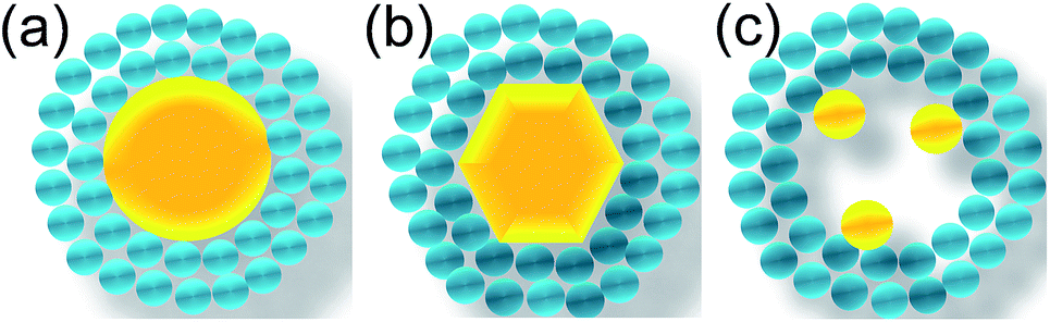 | ||
| Fig. 29 Noble metal@metal oxide core@shell NPs having different morphologies of core; (a) spherical, (b) hexagonal and (c) multiple cores. | ||
E. The volume between shell layer and core metal particles
It can be also used as micro-reactor to reform the analyte gas into more active gases. It has been found in our previous studies that the inwards diffusion of methyl benzene (toluene, xylene) to the underlying layer of the shell close to the catalyst NPs and its dissociation into more active smaller species by catalytic layers are the major factors behind the selective detection of methyl benzene.60,147 This can be used another strategy to design new gas sensing materials.5. Miscellaneous applications of metal@metal oxides core@shell nanostructures
In addition to the applications discussed above, core@shell NPs with different compositions could be used in many other applications, such as photocatalysis,18 dye-sensitized solar cells,40 catalysis,19 biological,90 and surface enhanced Raman spectroscopy (SERS).140 For examples, core@shell NPs are showing great potential for photocatalytic application, especially visible light photocatalysis, where surface plasmon phenomenon of noble metals (Au, Ag) has been used for visible light harvesting.34,43,47–50 Surface plasmon phenomenon of noble metals in the form of core@shell is also used for efficiency enhancement of dye-sensitized solar cells (DSSC).40,42,46 Core@shell NPs have many potential applications in many different fields given their unique properties.6. Conclusions
In this feature article, we have summarized the potential applications of core@shell NPs in gas sensing. In the past decade, various synthesis approaches have been developed for the preparation of core@shell NPs. Many exciting research contributions are highlighted in this overview, which includes various strategies for the synthesis of core@shell NPs with controllable sizes, shapes, compositions and architectures, and the design of new yolk@shell NPs for gas sensing applications, to illustrate the importance of core@shell NPs. These core@shell NPs have shown better sensing properties as compared to pure metal oxide as well as noble metal deposited metal oxides. The formation of metal oxide shell has provided thermal as well as chemical stability to noble metals. The surface plasmon resonance of noble metals can be used to further improve the gas sensing properties of core@shell NPs under light illumination. In order to harvest unique advantages of core@shell NPs, it is necessary to develop a general and facile method for the synthesis of high quality core@shell NPs with control in functionality, size, shape and structure at a low cost. The core@shell NPs are new and promising platform for high performance gas sensors because physical and chemical properties of core and shell NPs can be tuned or designed separately.Acknowledgements
This study was supported by Department of Science and Technology (DST), New Delhi, India vide DST-INSPIRE Faculty Scheme (DST/INSPIRE/04/2014/001318).Notes and references
- D. D. Lee and D. S. Lee, IEEE Sens. J., 2001, 1, 214–224 CrossRef CAS.
- G. Korotcenkov, Mater. Sci. Eng., B, 2007, 139, 1–23 CrossRef CAS PubMed.
- T. Seiyama, A. Kato, K. Fujiishi and M. Nagatani, Anal. Chem., 1962, 34, 1502–1503 CrossRef CAS.
- N. Taguchi, Jpn. Pat. Appl., S45–38200, 1962.
- http://www.figarosensor.com/.
- H. J. Kim and J. H. Lee, Sens. Actuators, B, 2014, 192, 607–627 CrossRef CAS PubMed.
- Y. B. Hahn, R. Ahmad and N. Tripathy, Chem. Commun., 2012, 48, 10369–10385 RSC.
- N. Yamazoe, G. Sakai and K. Shimanoe, Catal. Surv. Asia, 2003, 7, 63–75 CrossRef CAS.
- J. Wöllenstein, H. Böttner, M. Jaegle, W. J. Becker and E. Wagner, Sens. Actuators, B, 2007, 70, 196–202 CrossRef.
- Z. Jhang and K. Colbow, Sens. Actuators, B, 2007, 40, 47–52 Search PubMed.
- P. Montmeat, C. Pijolat, G. Tournier and J. P. Viricelle, Sens. Actuators, B, 2002, 84, 148–159 CrossRef CAS.
- M. Hübner, D. Koziej, J. D. Grunwaldt, U. Weimar and N. Barsan, Phys. Chem. Chem. Phys., 2012, 14, 13249–13254 RSC.
- S. Matsushima, Y. Teraoka, N. Miura and N. Yamazoe, Jpn. J. Appl. Phys., 1988, 27, 1798–18002 CrossRef CAS.
- P. M. Arnal, M. Comotti and F. Schüth, Angew. Chem., Int. Ed., 2006, 45, 8224–8227 CrossRef CAS PubMed.
- V. Subramanian, E. E. Wolf and P. V. Kamat, Langmuir, 2003, 19, 469–474 CrossRef CAS.
- R. G. Chaudhuri and S. Paria, Chem. Rev., 2012, 112, 2373–2433 CrossRef PubMed.
- W. Schärtl, Nanoscale, 2010, 2, 829–843 RSC.
- N. Zhang, S. Liu and Y. J. Xu, Nanoscale, 2012, 4, 2227–2238 RSC.
- G. Li and Z. Tang, Nanoscale, 2014, 6, 3995–4011 RSC.
- J. Liu, S. Z. Qiao, J. S. Chen, X. W. Lou, X. Xing and G. Q. Lu, Chem. Commun., 2011, 47, 12578–12591 RSC.
- M. Giersig, T. Ung, L. M. Liz-Marzan and P. Mulvaney, Adv. Mater., 1997, 9, 570–575 CrossRef CAS PubMed.
- B. O. Dabbousi, J. Rodriguez-Viejo, F. V. Mikulec, J. R. Heine, H. Mattoussi, R. Ober, K. F. Jensen and M. G. Bawendi, J. Phys. Chem. B, 1997, 101, 9463–9475 CrossRef CAS.
- T. Ung, L. M. Liz-Marzan and P. Mulvaney, J. Phys. Chem. B, 1999, 103, 6770–6773 CrossRef CAS.
- S. J. Oldenberg, R. D. Averitt, S. L. Westcott and N. J. Halas, Chem. Phys. Lett., 1998, 288, 243–247 CrossRef.
- Y. T. Yu and P. Dutta, Sens. Actuators, B, 2011, 157, 444–449 CrossRef CAS PubMed.
- D. Li, Q. He and J. Li, Adv. Colloid Interface Sci., 2009, 149, 28–38 CrossRef CAS PubMed.
- H. Zou, S. Wu and J. Shen, Chem. Rev., 2008, 108, 3393–3957 CrossRef PubMed.
- C. Sanchez, B. Julián, P. Belleville and M. Popall, J. Mater. Chem., 2005, 15, 3559–3592 RSC.
- P. Reiss, M. Protière and L. Li, Small, 2009, 5, 154–168 CrossRef CAS PubMed.
- A. Guerrero-Martínez, J. Pèrez-Juste and L. M. Liz-Marzán, Adv. Mater., 2010, 22, 1182–1195 CrossRef PubMed.
- Y. T. Yu and P. Mulvaney, Mater. Trans., 2004, 45, 964–967 CrossRef CAS.
- H. W. Kwon, Y. M. Lim, S. K. Tripathy, B. G. Kim, M. S. Lee and Y. T. Yu, Jpn. J. Appl. Phys., 2007, 46, 2567–2570 CrossRef CAS.
- J. Li and H. C. Zeng, Angew. Chem., Int. Ed., 2005, 44, 4342–4345 CrossRef CAS PubMed.
- X. F. Wu, H. Y. Song, J. M. Yoon, Y. T. Yu and Y. F. Chen, Langmuir, 2009, 25, 6438–6447 CrossRef CAS PubMed.
- M. K. Song, P. Rai, K. J. Ko, S. H. Jeon, B. S. Chon, C. H. Lee and Y. T. Yu, RSC Adv., 2014, 4, 3529–3535 RSC.
- Y. S. Kim, P. Rai and Y. T. Yu, Sens. Actuators, B, 2013, 186, 633–639 CrossRef CAS PubMed.
- D. A. H. Hanaor and C. C. Sorrell, J. Mater. Sci., 2011, 46, 855–874 CrossRef CAS.
- P. I. Gouma and M. J. Mills, J. Am. Ceram. Soc., 2001, 84, 619–622 CrossRef CAS PubMed.
- R. D. Shannon and J. A. Pask, Am. Mineral., 1964, 49, 1707–1717 CAS.
- J. Du, J. Qi, D. Wang and Z. Tang, Energy Environ. Sci., 2012, 5, 6914–6918 CAS.
- Z. W. Seh, S. Liu, S. Y. Zhang, K. W. Shah and M. Y. Han, Chem. Commun., 2011, 47, 6689–6691 RSC.
- W. L. Liu, F. C. Lin, Y. C. Yang, C. H. Huang, S. Gwo, M. H. Huang and J. S. Huang, Nanoscale, 2013, 5, 7953–7962 RSC.
- J. Goebl, J. B. Joo, M. Dahl and Y. Yin, Catal. Today, 2014, 225, 90–95 CrossRef CAS PubMed.
- D. Zhang, X. Song, R. Zhang, M. Zhang and F. Liu, Eur. J. Inorg. Chem., 2005, 1643–1648 CrossRef CAS PubMed.
- P. Wang, D. Wang, T. Xie, H. Li, M. Yang and X. Wei, Mater. Chem. Phys., 2008, 109, 181–183 CrossRef CAS PubMed.
- J. Qi, X. Dang, P. T. Hammond and A. M. Belcher, ACS Nano, 2011, 5, 7108–7116 CrossRef CAS PubMed.
- B. Cheng, Y. Le and J. Yu, J. Hazard. Mater., 2010, 177, 971–977 CrossRef CAS PubMed.
- X. F. Wu, Y. F. Chen, J. M. Yoon and Y.-T. Yu, Mater. Lett., 2010, 64, 2208–2210 CrossRef CAS PubMed.
- N. Zhang, S. Liu, X. Fu and Y. J. Xu, J. Phys. Chem. C, 2011, 115, 9136–9145 CAS.
- N. Zhou, L. Polavarapu, N. Gao, Y. Pan, P. Yuan, Q. Wang and Q. H. Xu, Nanoscale, 2013, 5, 4236–4241 RSC.
- G. Oldfield, T. Ung and P. Mulvaney, Adv. Mater., 2000, 12, 1519–1522 CrossRef CAS.
- Y. T. Yu and P. Dutta, J. Solid State Chem., 2011, 184, 312–316 CrossRef CAS PubMed.
- T. Yanagimoto, Y. T. Yu and K. Kaneko, Sens. Actuators, B, 2012, 166–167, 31–35 CrossRef CAS PubMed.
- S. K. Tripathy, A. Mishra, S. K. Jha, R. Wahab and A. A. Al-Khedhairy, Anal. Methods, 2013, 5, 1456–1462 RSC.
- K. Yu, Z. Wu, Q. Zhao, B. Li and Y. Xie, J. Phys. Chem. C, 2008, 112, 2244–2247 CAS.
- K. K. Haldar and A. Patra, Chem. Phys. Lett., 2008, 462, 88–91 CrossRef CAS PubMed.
- S. K. Tripathy, H. W. Kwon, Y. M. Leem, B. G. Kim and Y.-T. Yu, Chem. Phys. Lett., 2007, 442, 101–104 CrossRef CAS PubMed.
- R. J. Wu, D. J. Lin, M. R. Yu, M. H. Chen and H. F. Lai, Sens. Actuators, B, 2013, 178, 185–191 CrossRef CAS PubMed.
- S. Das, S. Sinha, B. Das, S. K. Suar, S. K. S. Parashar, M. Mohapatra, A. Mishra and S. K. Tripathy, J. Mater. Sci.: Mater. Electron., 2014, 25, 217–223 CrossRef CAS.
- P. Rai, S. M. Majhi, Y. T. Yu and J. H. Lee, RSC Adv., 2015, 5, 17653–17659 RSC.
- Z. L. Wang, Nano Today, 2010, 5, 540–552 CrossRef CAS PubMed.
- K. K. Haldar, T. Sen and A. Patra, J. Phys. Chem. C, 2008, 112, 11650–11656 CAS.
- F. R. Fan, Y. Ding, D. Y. Liu, Z. Q. Tian and Z. L. Wang, J. Am. Chem. Soc., 2009, 131, 12036–12037 CrossRef CAS PubMed.
- P. Li, Z. Wei, T. Wu, Q. Peng and Y. Li, J. Am. Chem. Soc., 2011, 133, 5660–5663 CrossRef CAS PubMed.
- M. E. Aguirre, H. B. Rodríguez, E. S. Roman, A. Feldhoff and M. A. Grela, J. Phys. Chem. C, 2011, 115, 24967–24974 CAS.
- H. R. Liu, G. X. Shao, J. F. Zhao, Z. X. Zhang, Y. Zhang, J. Liang, X. G. Liu, H. S. Jia and B. S. Xu, J. Phys. Chem. C, 2012, 116, 16182–16190 CAS.
- X. Yin, W. Que, D. Fei, F. Shen and Q. Guo, J. Alloys Compd., 2012, 524, 13–21 CrossRef CAS PubMed.
- H. Sun, J. He, J. Wang, S. Y. Zhang, C. Liu, T. Sritharan, S. Mhaisalkar, M. Y. Han, D. Wang and H. Chen, J. Am. Chem. Soc., 2013, 135, 9099–9110 CrossRef CAS PubMed.
- L. F. Zhu, H. Wang, X. S. Shen, L. Y. Chen, Y. W. Wang and H. Y. Chen, Small, 2012, 8, 1857–1862 CrossRef CAS PubMed.
- Y. Yang, S. Han, G. Zhou, L. Zhang, X. Li, C. Zou and S. Huang, Nanoscale, 2013, 5, 11808–11819 RSC.
- Y. Qin, Y. Zhou, J. Li, J. Ma, D. Shi, J. Chen and J. Yang, J. Colloid Interface Sci., 2014, 418, 171–177 CrossRef CAS PubMed.
- M. Misra, P. Kapur and M. L. Singla, Appl. Catal., B, 2014, 150–151, 605–611 CrossRef CAS PubMed.
- M. Misra, P. Kapur, M. K. Nayak and M. L. Singla, New J. Chem., 2014, 38, 4197–4203 RSC.
- L. Arroyo-Ramírez, C. Chen, M. Cargnello, C. B. Murray, P. Fornasiero and R. J. Gorte, J. Mater. Chem. A, 2014, 2, 19509–19514 Search PubMed.
- C. Xu, J. Xie, D. Ho, C. Wang, N. Kohler, E. G. Walsh, J. R. Morgan, Y. E. Chin and S. Sun, Angew. Chem., Int. Ed., 2008, 47, 173–176 CrossRef CAS PubMed.
- H. Liu, J. H. Wu, J. H. Min and Y. K. Kim, J. Alloys Compd., 2012, 537, 60–64 CrossRef CAS PubMed.
- G. Lopes, J. M. Vargas, S. K. Sharma, F. Béron, K. R. Pirota, M. Knobel, C. Rettori and R. D. Zysler, J. Phys. Chem. C, 2010, 114, 10148–10152 CAS.
- T. D. Schladt, M. I. Shukoor, K. Schneider, M. N. Tahir, F. Natalio, I. Ament, J. Becker, F. D. Jochum, S. Weber, O. Köhler, P. Theato, L. M. Schreiber, C. Sönnichsen, H. C. Schröder, W. E. G. Müller and W. Tremel, Angew. Chem., Int. Ed., 2010, 49, 3976–3980 CrossRef CAS PubMed.
- W. Jiang, Y. Zhou, Y. Zhang, S. Xuan and X. Gong, Dalton Trans., 2012, 4594–4601 RSC.
- Y. Zhang, H. Ding, Y. Liu, S. Pan, Y. Luo and G. Li, J. Mater. Chem., 2012, 22, 10779–10786 RSC.
- M. E. F. Brollo, R. López-Ruiz, D. Muraca, S. J. A. Figueroa, K. R. Pirota and M. Knobel, Sci. Rep., 2014, 4, 6839 Search PubMed.
- N. D. Cuonga, T. T. Hoa, D. Q. Khieu, T. D. Lam, N. D. Hoa and N. V. Hieu, J. Alloys Compd., 2012, 523, 120–126 CrossRef PubMed.
- X. Teng, D. Black, N. J. Watkins, Y. Gao and H. Yang, Nano Lett., 2003, 3, 261–264 CrossRef CAS.
- Y. J. Baek, Q. Hu, J. W. Yoo, Y. J. Choi, C. J. Kang, H. H. Lee, S. H. Min, H. M. Kim, K. B. Kim and T. S. Yoon, Nanoscale, 2013, 5, 772–779 RSC.
- Y. Sun, B. Yang, Y. Tian, G. Guo, W. Cai, M. He and Y. Liu, Micro Nano Lett., 2011, 6, 82–85 CAS.
- H. Yin, Z. Ma, M. Chi and S. Dai, Catal. Today, 2011, 160, 87–95 CrossRef CAS PubMed.
- K. S. Chou, M. Y. Lin and H. H. Wu, J. Taiwan Inst. Chem. Eng., 2013, 44, 228–232 CrossRef CAS PubMed.
- Y. Chen, N. Gao and J. Jiang, Small, 2013, 9, 3242–3246 CAS.
- E. V. Shevchenko, M. I. Bodnarchuk, M. V. Kovalenko, D. V. Talapin, R. K. Smith, S. Aloni, W. Heiss and A. P. Alivisatos, Adv. Mater., 2008, 20, 4323–4329 CrossRef CAS PubMed.
- Z. Wei, Z. Zhou, M. Yang, C. Lin, Z. Zhao, D. Huang, Z. Chen and J. Gao, J. Mater. Chem., 2011, 21, 16344–16348 RSC.
- S. Xuan, Y. Zhou, H. Xu, W. Jiang, K. C. F. Leung and X. Gong, J. Mater. Chem., 2011, 21, 15398–15404 RSC.
- Y. Q. Wang, K. Nikitin and D. W. McComb, Chem. Phys. Lett., 2008, 456, 202–205 CrossRef CAS PubMed.
- C. H. Kuo, T. E. Hua and M. H. Huang, J. Am. Chem. Soc., 2009, 131, 17871–17878 CrossRef CAS PubMed.
- W. C. Wang, L. M. Lyu and M. H. Huang, Chem. Mater., 2011, 23, 2677–2684 CrossRef CAS.
- S. C. Hsu, S. Y. Liu, H. J. Wang and M. H. Huang, Small, 2015, 11, 195–201 CrossRef CAS PubMed.
- L. Zhang, D. A. Blom and H. Wang, Chem. Mater., 2011, 23, 4587–4598 CrossRef CAS.
- L. Kong, W. Chen, D. Ma, Y. Yang, S. Liu and S. Huang, J. Mater. Chem., 2012, 22, 719–724 RSC.
- J. Li, S. K. Cushing, J. Bright, F. Meng, T. R. Senty, P. Zheng, A. D. Bristow and N. Wu, ACS Catal., 2013, 3, 47–51 CrossRef CAS.
- S. K. Cushing, J. Li, F. Meng, T. R. Senty, S. Suri, M. Zhi, M. Li, A. D. Bristow and N. Wu, J. Am. Chem. Soc., 2012, 134, 15033–15041 CrossRef CAS PubMed.
- D. Y. Liu, S. Y. Ding, H. X. Lin, B. J. Liu, Z. Z. Ye, F. R. Fan, B. Ren and Z. Q. Tian, J. Phys. Chem. C, 2012, 116, 4477–4483 CAS.
- L. Zhang, H. Jing, G. Boisvert, J. Z. He and H. Wang, ACS Nano, 2012, 6, 3514–3527 CrossRef CAS PubMed.
- N. Meir, I. J. L. Plante, K. Flomin, E. Chockler, B. Moshofsky, M. Diab, M. Volokh and T. Mokari, J. Mater. Chem. A, 2013, 1, 1763–1769 CAS.
- Y. C. Yang, H. J. Wang, J. Whang, J. S. Huang, L. M. Lyu, P. H. Lin, S. Gwo and M. H. Huang, Nanoscale, 2014, 6, 4316–4324 RSC.
- H. Jing, N. Large, Q. Zhang and H. Wang, J. Phys. Chem. C, 2014, 118, 19948–19963 CAS.
- P. Rai, R. Khan, S. Raj, S. M. Majhi, K. K. Park, Y. T. Yu, I. H. Lee and P. K. Sekhar, Nanoscale, 2014, 6, 581–588 RSC.
- S. M. Majhi, P. Rai, S. Raj, B. S. Chon, K. K. Park and Y. T. Yu, ACS Appl. Mater. Interfaces, 2014, 6, 7491–7497 CAS.
- Y. K. Lin, Y. J. Chiang and Y. J. Hsu, Sens. Actuators, B, 2014, 204, 190–196 CrossRef CAS PubMed.
- J. Xiong, Z. Li, J. Chen, S. Zhang, L. Wang and S. Dou, ACS Appl. Mater. Interfaces, 2014, 6, 15716–15725 CAS.
- L. Xu, M. L. Yin and S. Liu, J. Alloys Compd., 2015, 623, 127–131 CrossRef CAS PubMed.
- L. Xu, M. L. Yin and S. Liu, Sci. Rep., 2014, 4, 6745 CrossRef CAS PubMed.
- X. Li, J. Liu, H. Guo, X. Zhou, C. Wang, P. Sun, X. Hu and G. Lu, RSC Adv., 2015, 5, 545–551 RSC.
- X. Sun and Y. Li, Angew. Chem., Int. Ed., 2004, 43, 597–601 CrossRef PubMed.
- T. Kayama, K. Yamazaki and H. Shinjoh, J. Am. Chem. Soc., 2010, 132, 13154–13155 CrossRef CAS PubMed.
- K. Yamazaki, T. Kayama, F. Dong and H. Shinjoh, J. Catal., 2011, 282, 289–298 CrossRef CAS PubMed.
- T. Mitsudome, Y. Mikami, M. Matoba, T. Mizugaki, K. Jitsukawa and K. Kaneda, Angew. Chem., Int. Ed., 2012, 51, 136–139 CrossRef CAS PubMed.
- T. Mitsudome, M. Matoba, T. Mizugaki, K. Jitsukawa and K. Kaneda, Chem.–Eur. J., 2013, 19, 5255–5258 CrossRef CAS PubMed.
- X. Wang, D. Liu, S. Song and H. Zhang, J. Am. Chem. Soc., 2013, 135, 15864–15872 CrossRef CAS PubMed.
- J. Qi, J. Chen, G. Li, S. Li, Y. Gao and Z. Tang, Energy Environ. Sci., 2012, 5, 8937–8941 CAS.
- N. Zhang, X. Fu and Y.-J. Xu, J. Mater. Chem., 2011, 21, 8152–8158 RSC.
- N. Zhang and Y.-J. Xu, Chem. Mater., 2013, 25, 1979–1988 CrossRef CAS.
- J. Hu, Z. Wen, Q. Wang, X. Yao, Q. Zhang, J. Zhou and J. Li, J. Phys. Chem. B, 2006, 110, 24305–24310 CrossRef CAS PubMed.
- B. Y. Kim, I.-B. Shim, Z. O. Araci, S. S. Saavedra, O. L. A. Monti, N. R. Armstrong, R. Sahoo, D. N. Srivastava and J. Pyun, J. Am. Chem. Soc., 2010, 132, 3234–3235 CrossRef CAS PubMed.
- Z. Zhuang, W. Sheng and Y. Yan, Adv. Mater., 2014, 26, 3950–3955 CrossRef CAS PubMed.
- K. Maeda, K. Teramura, D. Lu, N. Saito, Y. Inoue and K. Domen, Angew. Chem., Int. Ed., 2006, 45, 7806–7809 CrossRef CAS PubMed.
- N. Sakamoto, H. Ohtsuka, T. Ikeda, K. Maeda, D. Lu, M. Kanehara, K. Teramura, T. Teranishi and K. Domen, Nanoscale, 2009, 1, 106–109 RSC.
- P. M. Arnal, M. Comotti and F. Schüth, Angew. Chem., Int. Ed., 2006, 45, 8224–8227 CrossRef CAS PubMed.
- I. Lee, J. B. Joo, Y. Yin and F. Zaera, Angew. Chem., Int. Ed., 2011, 50, 10208–10211 CrossRef CAS PubMed.
- L. Wang, H. Dou, Z. Lou and T. Zhang, Nanoscale, 2013, 5, 2686–2691 RSC.
- X. Huang, C. Guo, J. Zuo, N. Zheng and G. D. Stucky, Small, 2009, 5, 361–365 CrossRef CAS PubMed.
- C. Galeano, R. Güttel, M. Paul, P. Arnal, A. H. Lu and F. Schüth, Chem.–Eur. J., 2011, 17, 8434–8439 CrossRef CAS PubMed.
- R. Güttel, M. Paul and F. Schüth, Chem. Commun., 2010, 46, 895–897 RSC.
- C. Chen, X. Fang, B. Wu, L. Huang and N. Zheng, ChemCatChem, 2012, 4, 1578–1586 CrossRef CAS PubMed.
- P. Rai, J. W. Yoon, H. M. Jeong, S. J. Hwang, C. H. Kwak and J. H. Lee, Nanoscale, 2014, 6, 8292–8299 RSC.
- X. Li, X. Zhou, H. Guo, C. Wang, J. Liu, P. Sun, F. Liu and G. Lu, ACS Appl. Mater. Interfaces, 2014, 6, 18661–18667 CAS.
- C. K. Ngaw, Q. Xu, T. T. Y. Tan, P. Hu, S. Cao and J. S. C. Loo, Chem. Eng. J., 2014, 257, 112–121 CrossRef CAS PubMed.
- F. C. Chung, R. J. Wu and F. C. Cheng, Sens. Actuators, B, 2014, 190, 1–7 CrossRef CAS PubMed.
- Z. Zhu, C. T. Kao and R. J. Wu, Appl. Surf. Sci., 2014, 320, 348–355 CrossRef CAS PubMed.
- S. M. Majhi, P. Rai and Y. T. Yu, ACS Appl. Mater. Interfaces, 2015, 7, 9462–9468 CAS.
- L. W. Jang, D. W. Jeon, T. Sahoo, A. Y. Polyakov, B. Sarvanakumar, Y. T. Yu, Y. H. Cho and I. H. Lee, J. Mater. Chem., 2012, 22, 21749–21753 RSC.
- L. Sun, J. He, S. An, J. Zhang and D. Ren, J. Mol. Struct., 2013, 1046, 74–81 CrossRef CAS PubMed.
- H. L. Jiang, B. Liu, T. Akita, M. Haruta, H. Sakurai and Q. Xu, J. Am. Chem. Soc., 2009, 131, 11302–11303 CrossRef CAS PubMed.
- W. Eberhardt, S. G. Louie and E. W. Plummer, Phys. Rev. B: Condens. Matter Mater. Phys., 1983, 28, 465–477 CrossRef CAS.
- J. Zhang, C. Xi, C. Feng, H. Xia, D. Wang and X. Tao, Langmuir, 2014, 30, 2480–2489 CrossRef CAS PubMed.
- O. Rosseler, A. Louvet, V. Keller and N. Keller, Chem. Commun., 2011, 47, 5331–5333 RSC.
- H. M. Song, D. H. Anjum, R. Sougrat, M. N. Hedhili and N. M. Khashab, J. Mater. Chem., 2012, 22, 25003–25010 RSC.
- X. Liu, A. Wang, X. Yang, T. Zhang, C. Y. Mou, D. S. Su and J. Li, Chem. Mater., 2009, 21, 410–418 CrossRef CAS.
- Y. J. Hong, J. W. Yoon, J. H. Lee and Y. C. Kang, Chem.–Eur. J., 2014, 20, 2737–2741 CrossRef CAS PubMed.
| This journal is © The Royal Society of Chemistry 2015 |