Fabrication of nickel oxide nanostructures with high surface area and application for urease-based biosensor for urea detection

Hien Duy Maia, Gun Yong Sung*b and Hyojong Yoo*a
aDepartment of Chemistry, Hallym University, Chuncheon, Gangwon-do 200-702, Republic of Korea. E-mail: hyojong@hallym.ac.kr
bDepartment of Materials Science and Engineering, Hallym University, Chuncheon, Gangwon-do 200-702, Republic of Korea. E-mail: gysung@hallym.ac.kr

Received 17th July 2015 , Accepted 8th September 2015

First published on 10th September 2015


Abstract

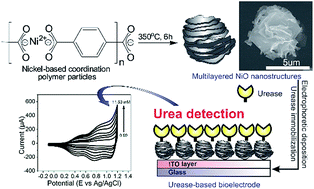
Uniform nanostructured nickel-based coordination polymer particles with multilayered morphologies (mL-NiCPPs) were successfully fabricated through a two-step heating process. To increase the surface area by reducing the size of mL-NiCPPs, pyridine and acetic acid were added as size modulators during the growth process. The resultant coordination polymer nanoparticles were then calcinated at a controlled temperature in order to produce nickel oxide nanostructures (mL-NiOs), which have a regular multilayered morphology and a high degree of crystallinity. Moreover, the mL-NiOs had a relatively high BET specific surface area (112 m2 g−1) and a well-defined pore size (10 nm), hence exhibited significant potential for use in a variety of applications. The synthesized mL-NiOs were successfully deposited onto indium tin oxide (ITO) serving as an efficient matrix for the immobilization of urease (Ur), which was used for urea detection. The prepared bioelectrode (Ur/NiO/ITO/glass) was employed for urea sensing using cyclic voltammetry (CV). The prepared electrodes showed a high sensitivity and a linear dependence of the current on the urea concentration.

Introduction

Biosensing has recently attracted significant interest owing to the many prominent applications, ranging from medical diagnosis to detection of environmental contaminants, for which it is well-suited.1,2 In biosensors, enzymes and a suitable transducer are employed as the molecular recognition elements and signal detectors, respectively; these sensors therefore have substantially higher specificity and sensitivity, and more rapid response time compared to non-enzymatic sensors.3 Over the past decades, significant emphasis has been placed on developing advanced bioelectronic devices, which quantitatively detect abnormal levels of various essential analytes (e.g. glucose,4 cholesterol,5 and urea6); these analytes are considered indicators of the functional deficiency of certain human organs. As such, in the current work, a urease-based bioelectronics sensor was fabricated for the quantitative monitoring of urea concentration in human serum, due to its clinical significance in diagnosing the potential failure of kidney or liver functions.7

Issues such as low operational stability and difficulty in enzyme immobilization on bare electrodes, which stem from the intrinsic properties of enzymes, have often limited the use of biosensors in practical applications. More importantly, electrons arising from the biological redox reaction of proteins are prohibitively transferred to bare electrodes since the redox center of the enzyme is surrounded by a thick insulating protein shell; the space between the redox center and the electrode could be, in general, greater than the critical electron tunneling distance.8,9 The aforementioned drawbacks of biosensors can be overcome by the entrapment of an enzyme onto a matrix possessing high conductivity, good biocompatibility, and suitable hydrophilicity.10 The selection of an appropriate solid matrix, which facilitates the immobilization of the desired biomolecules is, therefore, essential. A variety of materials have been developed in recent years, among which metal oxide nanomaterials appear to be ideal candidates for enhancing the performance of biosensors; these nanomaterials are ideal candidates owing to their excellent biocompatibility, non-toxicity, strong adsorption capability, and electron transfer properties.11 In addition, the physical adsorption method (via e.g. van der Waals forces, hydrophobic interactions, hydrogen binding, and electrostatic interactions) has recently been used to efficiently impregnate enzymes on metal oxide substrates; this method is particularly attractive owing to its simplicity and ability to preserve enzyme activity.10,12–14 The isoelectric point (pI) of the enzyme and the point of zero charge (pzc) of the support are essential to the immobilization of proteins.10 In this work, nickel oxide nanoparticles are employed as a substrate material for fabricating urease-based biosensors due to their exceptionally high pzc (pzc = 10.7); these nanoparticles are effective in immobilizing urease, which has a low pI (pI = 5), via a strong electrostatic interaction.11,15 The entrapment of enzymes and the electrochemical performance are also governed by textural properties (e.g. dimension, surface area, porosity, and geometry) of the nanomaterials. The effect of these properties results mainly from nanomaterials being composed of high densities of low-coordinated atoms that serve as active sties onto which enzyme molecules can be efficiently adsorbed.10,16 Therefore, engineering nanostructured metal oxides, which have anisotropic geometries, tunable pore size, and high surface area is crucial for the construction of bioelectronic devices.17

Metal–organic frameworks or coordination polymer particles (CPPs) are judiciously constructed by assembling rigid metal-containing building blocks with organic linkers into ordered networks, which are held together by strong bonding.18–20 Various topologies, structural skeleton, and pore apertures can also be tailored through rational linker design.21–25 In addition, recent studies have indicated that coordination polymers could be used as sacrificial templates for the synthesis of hierarchically porous nanomaterials, primarily via thermolysis.26–34 In this paper, we describe a facile method to construct uniform nanostructured nickel-based coordination polymer particles with multilayered morphologies (mL-NiCPPs). These anisotropic morphologies are attained via a two-step synthetic process. This process consists of the high-temperature nucleation, followed by a growth process, during which mL-NiCPPs are formed from the gradual low-temperature polymerization of the pre-synthesized nuclei. Moreover, in the growth process, the average size of the mL-NiCPPs is reduced by introducing additive modulators (pyridine and acetic acids), which play a key role in the formation of nanosized mL-NiCPPs. The obtained mL-NiCPPs were subsequently calcinated in air at a controlled temperature, resulting in hierarchically porous multilayered NiO nanoparticles (mL-NiOs), which constitute an extraordinary high surface area. Due to this extraordinarily high surface area, monodisperse pore size, and intrinsically high pzc, the obtained mL-NiOs were used to fabricate urease-based NiO biosensors for urea detection; these biosensors exhibit high sensitivity and excellent linearity over a wide range of concentration of urea.

Experimental section

Reagents

Nickel(II) nitrate hexahydrate (Ni(NO3)2·6H2O, 97%, Sigma-Aldrich), benzene-1,4-dicarboxylic acid (C8H6O4, 98%, Sigma-Aldrich), pyridine (C5H5N, 99.8%, Burdick & Jackson), acetic acid (CH3COOH, 99.7%, Junsei), urease (from Canavalia ensiformis (Jack bean), 34[thin space (1/6-em)]310 units per g solid, Sigma-Aldrich), sodium phosphate dibasic dehydrate (HNa2O4P·2H2O, 99%, Sigma-Aldrich), sodium phosphate monobasic monohydrate (H2NaO4P·H2O, 99%, Sigma-Aldrich), dimethylformamide (DMF), and ethyl ether were used as received. All stock solutions were freshly prepared before each reaction. Prior to use, all glassware was washed with aqua regia (volume ratio of 3[thin space (1/6-em)]:[thin space (1/6-em)]1 of concentrated HCl and HNO3; Caution: aqua regia is highly toxic and corrosive and must be handled in fume hoods with proper personal protection equipment) and rinsed thoroughly with deionized water. Abbreviations used: H2BDC = benzene-1,4-dicarboxylic acid.

Synthesis of multilayered nickel-based coordination polymers (mL-NiCPPs)

The synthetic method for multilayered nickel-based coordination polymers (mL-NiCPPs) consists of two steps. In the first step, 16 mL of 0.1 M Ni(NO3)2 (1.8 mmol) and 24 mL of 0.1 M H2BDC (2.4 mmol) were gently stirred in DMF in a round-bottle flask at 130 °C for 30 min. The color of the reaction mixture gradually changed from a green to yellowish green. In the second step, 600 μL of 1.55 M pyridine (0.93 mmol) and 450 μL of 8.7 M acetic acid (3.92 mmol) were subsequently added into the reaction mixture. The final mixture was maintained at 80 °C for 24 hours to ensure a complete reaction, resulting in a green colloidal solution. Green products were repeatedly washed with DMF (2 times) and ethyl ether (4 times) and then dried at 80 °C for 12 hours.

Synthesis of multilayered nickel oxide nanostructures (mL-NiOs)

The pre-synthesized mL-NiCPPs were annealed in air at 350 °C for 6 hours and then cooled to room temperature. The resultant product was black, indicating the formation of mL-NiOs.

For comparison with the two-step heating process, two different samples of nickel-based coordination polymer particles (Ni-CPPs) were synthesized in one step by heating the reaction mixture (consistent amounts of Ni2+, H2BDC, and modulators were used) at 130 °C (130-Ni-CPPs) and 80 °C (80-Ni-CPPs) for 24 h. The 80-Ni-CPPs and 130-Ni-CPPs samples were subsequently calcinated at 350 °C for 6 h to produce NiO particles (130-NiOs and 80-NiOs, respectively).

For assessing the size controllability of modulators, a sample of Ni-CPPs was prepared without the use of modulators (mo-Ni-CPPs). The mo-Ni-CPPs were subsequently calcinated at 350 °C for 6 h to produce NiO particles (mo-NiOs).

Fabrication of urease-immobilized bioelectrode (Ur-NiO/ITO)

Typically, to fabricate NiO/ITO electrodes, 10 mg of the obtained mL-NiOs were suspended into 10 mL of toluene followed by sonication for 10 min. The mL-NiOs were electrically deposited onto an ITO electrode using electrophoretic deposition (EPD). Prior to the electrical deposition of mL-NiOs, ITO electrodes were cleaned using oxygen plasma for 30 seconds (energy = 100 W, pressure = 0.41 torr). Two identical ITO electrodes were dipped in the deposition solution (1 cm separation distance) and a constant direct current (DC) voltage of 90 V was applied using an Agilent N5751A DC power supply for 1 h (Fig. S1). The obtained NiO/ITO electrode was sequentially rinsed with ethanol and water. The urease-based NiO/ITO (Ur-NiO/ITO) bioelectrode was prepared by dipping the NiO/ITO electrode into a urease solution (5 mg mL−1, in 10 mM PBS buffer, pH 7). This step was repeated 5 times followed by rinsing with water to remove loosely bonding enzymatic molecules. The electrode was then dried at room temperature overnight and stored at 4 °C in a PBS buffer (10 mM, pH 7) prior to use.

Reproducibility and stability of Ur-NiO/ITO bioelectrode

To investigate the reproducibility of Ur-NiO/ITO bioelectrode, six repetitive CV experiments were conducted in PBS solution containing 2 mM urea. After each cycle, the bioelectrode was rinsed with water and ready for the next CV experiment. The lifetime of the bioelectrode was also evaluated throughout a period of 5 days, with one experiment per day. After each experiment, the bioelectrode was rinsed with water and stored in PBS solution at 4 °C in a fridge.

Characterization

The nanoparticles were imaged using a Hitachi S-4800 scanning electron microscope (SEM). Absorption spectra were recorded with a UV-Vis spectra spectrometer (UVIKON XS). IR spectra from 399 to 4000 cm−1 were recorded using KBr pellets on a Nicolet iS5 FT/IR spectrometer (Thermo Scientific). The pH of solutions was measured using an Orion 420A+ pH meter. Powder X-ray diffraction (PXRD) was performed with a RIGAKU Ultima IV diffractometer using Cu Kα radiation (wavelength 1.541 Å) in focused beam and a continuous scan rate of 0.09° min−1 in the range 30–90°. N2 adsorption isotherms obtained using BELSORP-mini II (BEL Japan, Inc.) were used to characterize the specific surface area, total pore volume, and pore size of materials. Prior to gas adsorption experiments, all samples were completely dried at 395 K for 12 h. The specific surface area is estimated from Brunauer–Emmett–Teller (BET) equation in a low relative pressure range (P/P0, 0.1 to 0.3). The pore size distribution and total pore volume are calculated from Barrett–Joyner–Halenda (BJH) equation using data from the desorption curve. The cyclic voltammetry (CV) experiments including urea sensing experiments were carried out in a conventional three-electrode cell at ambient temperature (∼25 °C) using CHI 605B Electrochemical Workstation (CH Instruments, Inc.) and VersaSTAT 3 (Princeton Applied Research). Throughout the CV experiments, the potential window was set between −0.2 V and 1.1 V. Prior to experiments, the electrolyte solution (NaCl 7%ww in PBS buffer, pH 7) was degassed by bubbling with nitrogen for 30 min. Platinum wire and a Ag/AgCl electrode were employed as counter and reference electrodes, respectively.

Results and discussion

Morphological and physical characterization of multilayered Ni-CPPs (mL-NiCPPs) and multilayered NiO nanostructures (mL-NiOs)

The multilayered NiO nanostructures (mL-NiOs) were synthesized as shown in Scheme 1. Using the two-step method, multilayered Ni-CPPs (mL-NiCPPs) were initially produced from the reaction of Ni(NO3)2·6H2O in DMF, with the assistance of modulators (acetic acid and pyridine); these mL-NiCPPs were subsequently converted to the NiO phase via calcination at 350 °C for 6 h, thereby resulting in highly porous mL-NiOs.
image file: c5ra14103f-s1.tif
Scheme 1 The synthesis of porous multilayered NiO nanostructures (mL-NiOs) from multilayered Ni-CPPs (mL-NiCPPs) via calcination.

The scanning electron microscopy (SEM) images of the mL-NiCPPs and mL-NiOs are shown in Fig. 1 and S2. The mL-NiCPPs exhibiting multilayered topologies are composed of numerous plates with nanoscale thickness of approximately 300 nm (Fig. 1a and b and S2). In addition, the obtained mL-NiOs retained their original anisotropic multilayered structure, which consists of many rough and edge-rich surfaces (Fig. 1c and d). The PXRD analysis (Fig. 1e) confirmed that the mL-NiCPPs precursors were completely transformed to nickel oxides (reference code 01-078-0643 (ref. 35)). Furthermore, the sharp diffraction peaks are indicative of the high crystallinity of the obtained mL-NiOs.


image file: c5ra14103f-f1.tif
Fig. 1 SEM images of mL-NiCPPs (a and b); mL-NiOs obtained from calcinating the mL-NiCPPs (c and d); (e) powder X-ray diffraction pattern of the mL-NiOs.

The N2 adsorption isotherms of the mL-NiCPPs and mL-NiOs are shown in Fig. 2a. The mL-NiOs have an estimated BET surface area of 112 m2 g−1, which is significantly higher than that (6.5 m2 g−1) of the mL-NiCPPs. This substantial enhancement in surface area of mL-NiOs results possibly from the elimination of the organic linker during calcination. In addition, the pronounced hysteresis associated with the adsorption behavior of the mL-NiOs, was not observed in the case of the mL-NiCPPs. This further indicates that a new mesoporous system corresponding to a monodisperse pore size located at ∼10 nm (curve (ii) in Fig. 2b), was generated. To the best of our knowledge, the surface area (112 m2 g−1) of the mL-NiOs is among the highest values recently reported (Table S1).


image file: c5ra14103f-f2.tif
Fig. 2 (a) N2 adsorption isotherms of (i) mL-NiCPPs (-□-) and (ii) mL-NiOs (-○-); (b) pore size distribution curve of (i) mL-NiCPPs (dotted) and (ii) mL-NiOs (solid).

The mL-NiCPPs are produced by the 30 min high-temperature (130 °C), followed by a gradual low-temperature (80 °C) treatments to give uniform multilayered topologies. The superiority of the two-step heating process in enhancing the surface area was demonstrated by preparing two other NiO samples using nickel-based coordination polymer particle (Ni-CPPs) precursors. These precursors were synthesized by a one-step method and estimated BET surface area values of NiO samples were used as an evaluation criterion. Specifically, Ni-CPPs were prepared in one step by heating the reaction mixture (consistent amounts of Ni2+, H2BDC, and modulators were used) at 130 °C (130-Ni-CPPs) and 80 °C (80-Ni-CPPs) for 24 h. The corresponding SEM images (Fig. 3a and b) reveal the hexagonal plates and a morphological polydispersity present in the 130-Ni-CPPs and 80-Ni-CPPs, respectively. In addition, the 80-Ni-CPPs formed only after 96 hours, owing probably to the low reaction temperature. The 80-Ni-CPPs and 130-Ni-CPPs samples were subsequently calcinated at 350 °C for 6 h to produce NiO particles, denoted as 130-NiOs and 80-NiOs, respectively. The surface area values of 130-NiOs and 80-NiOs materials estimated from N2 adsorption isotherms (Fig. 3d, black and red lines, respectively) were 35 and 25 m2 g−1, respectively. These values are substantially lower than that of mL-NiOs, which were thermally converted from mL-NiCPPs synthesized using the two-step heating method. Our proposed two-step method is based on the LaMer diagram,36,37 in which the first step results in a rapid nucleation. In the second step, this rapid nucleation is followed by a thermodynamically-favored crystallization and polymerization, which generates ordered and uniform mL-NiCPPs. Consequently, the mL-NiOs resulting from the conversion of the mL-NiCPPs exhibit significantly enhanced surface area.


image file: c5ra14103f-f3.tif
Fig. 3 SEM images: of Ni-CPPs prepared by the one-step method at (a) 130 °C (130-Ni-CPPs) and (b) 80 °C (80-Ni-CPPs); and of (c) mo-Ni-CPPs prepared without modulators; (d) N2 adsorption isotherms of the 130-NiOs (black line,-□-), 80-NiOs (red line,-○-), and mo-NiOs (blue line, -△-). N2 desorption isotherms were not shown for clarity.

Monodentate ligands, i.e., so-called modulators, can function as ligands that compete with the organic linkers at metal centers, and thereby control the rate of crystal growth and hence the crystal size.38–40 In order to investigate the influence of modulators (acetic acid and pyridine) on the size of the Ni-CPPs, a sample of Ni-CPPs was prepared without the use of modulators (mo-Ni-CPPs). The SEM image of the obtained mo-Ni-CPPs (Fig. 3c) shows that the Ni-CPPs fabricated without the use of modulators are larger than those fabricated with the use of modulators; the mo-Ni-CPPs, as shown in Fig. 3c, are ∼15 μm large. Moreover, the N2 adsorption isotherm of mo-NiOs, which were thermally converted from mo-Ni-CPPs, (blue line, Fig. 3d) indicates that the surface areas of these particles decrease markedly to 18.5 m2 g−1. This could be attributed to that, in addition to controlling the particle size, modulators can terminate the polymerization and thereby enable the generation of voids, which, in turn, enhances the surface area of the materials.

Preparation of NiO/ITO and Ur-NiO/ITO electrodes

The current reproducibility and reusability of bioelectrodes depend directly on the stability of the NiO transducer on ITO electrodes. A simple, consistent, and broadly applicable deposition method is therefore required to obtain this stability. Recently, electrophoretic deposition (EPD) has been extensively used to fabricate thin films of semiconducting,41 metallic,42 insulating,43 and metal–organic framework44 particles on conductive substrates. In this work, NiO/ITO electrodes were fabricated via two techniques, namely dip coating and the EPD method, and cyclic voltammograms (CVs) were recorded for a preliminary comparison of their electrochemical behaviors. Fig. S3 and S4 show the CVs of the NiO/ITO electrodes prepared by dip coating method and EPD, respectively. The scheme in Fig. S1 shows the fabrication of NiO/ITO electrodes via the EPD method; the histogram in Fig. 4 compares the oxidation peak currents at 0.8 V (vs. Ag/AgCl) obtained at different scan rates of the NiO/ITO electrodes prepared by each method. It is noticed that the oxidation currents of the EPD-prepared NiO/ITO electrode are significantly higher than those of dip-coated counterparts. This suggests that the stability of the electrode was enhanced and many more mL-NiOs were deposited on the ITO by EPD than by dip coating. As such, for subsequent fabrication of bioelectrodes, EPD was used to deposit mL-NiOs onto the ITO.
image file: c5ra14103f-f4.tif
Fig. 4 Histogram comparing the oxidation peak currents (at ∼0.8 V) obtained at different scan rates (50 to 200 mV s−1) of the NiO/ITO electrodes prepared via the dip coating and EPD methods.

The obtained NiO/ITO electrodes using EPD method were subsequently employed to fabricate bioelectrodes. Urease adsorption amount on the NiO/ITO electrode, which was quantitatively determined using ultraviolet-visible (UV-Vis) spectroscopy, was approximately 4.02 mg (Fig. S5). Fourier transform infrared spectroscopy (FTIR) was also employed to confirm the successful urease incorporation onto NiO/ITO electrodes (Fig. S6).

Electrochemical characterization

Fig. 5 shows the CVs of the bare ITO, NiO/ITO, and Ur-NiO/ITO electrodes recorded in a PBS buffer (10 mM; pH 7; NaCl 7%ww) at a scan rate of 100 mV s−1. Owing to the absence of redox couple from the surface, oxidation and reduction peaks are correspondingly absent from the CV of the bare ITO electrode (Fig. 5(i)). The CV of the NiO/ITO electrode (Fig. 5(ii)), conversely, exhibits peaks at ∼0.45 and 0.85 V, which correspond to two well-established redox couples. Previous works have shown that the NiO electrodes exhibit oxidation and reduction peaks arising from the Ni(OH)2/NiOOH reversible redox couple only (eqn (1)).15,45–48 In the current work, however, the NiO/ITO electrode exhibits two distinct redox couples corresponding possibly to two different electron transfer processes. The redox reaction at high potential (∼0.8 V) is attributed to the well-known Ni(OH)2/NiOOH couple;49 the anomalous couple at low potential (∼0.4 V) results possibly from the reduction of existing α-Ni(OH)2 back to metallic Ni (eqn (2)).49,50 In contrast, the α-Ni(OH)2 phase can be irreversibly transformed by dehydration to β-Ni(OH)2,51 which cannot be reduced back to metallic Ni. This may explain the absence of redox peaks corresponding to α-Ni(OH)2/Ni from the CV diagrams of the NiO/ITO electrodes (Fig. S7). Therefore, due to its reversibility and consistency, only the Ni(OH)2/NiOOH redox couple is discussed hereafter for both NiO/ITO and Ur-NiO/ITO electrodes. Comparison of the magnitudes of the oxidation peaks of the Ur-NiO/ITO bioelectrode (Fig. 5(iii)) and the NiO/ITO electrode reveals that the former (50 μA) is significantly lower than the latter (160 μA). This significant difference is attributed to the intrinsic hindrance stemming from the non-conducting nature of enzymes, and is indicative of urease immobilization.
 
β-Ni(OH)2 → NiOOH + H+ + e (1)
 
α-Ni(OH)2 + 2e → Ni + 2OH (2)

image file: c5ra14103f-f5.tif
Fig. 5 CVs of the (i) bare ITO; (ii) NiO/ITO; (iii) Ur-NiO/ITO electrodes recorded in a PBS buffer (10 mM; pH 7; NaCl 7%ww) without an external mediator. Scan rate: 100 mV s−1.

Fig. 6 shows the CVs of the Ur-NiO/ITO bioelectrode recorded at scan rates of 50–200 mV s−1. As the figure shows, the anodic and cathodic peaks, which correspond to the Ni(OH)2/NiOOH redox couple, shift only slightly to positive and negative potentials, respectively, with increasing scan rate. Although the shifts still possibly result from the resistance of the NiO layer,52 they show only insignificant changes owing to the fast electron communication of the bioelectrode. In addition, the linear dependence of the redox peak currents on the square root of the scan rate, v1/2 (insert in Fig. 6), indicates that the electron transfer process is diffusion-controlled (eqn (3) and (4));53,54 i.e.,

 
Ia (Ur-NiO/ITO) [μA] = 6.49 [μA s mV−1] × {scan rate (mV s−1)}1/2 − 25.99 [μA] (3)
 
Ic (Ur-NiO/ITO) [μA] = −4.40 [μA s mV−1] × {scan rate (mV s−1)}1/2 + 17.08 [μA] (4)


image file: c5ra14103f-f6.tif
Fig. 6 Cyclic voltammograms (CVs) recorded at scan rates of 50–200 mV s−1 for the Urease-NiO/ITO (Ur-NiO/ITO) electrode in the PBS solution (10 mM, pH 7). The insert shows plots of the anodic (Ia) and cathodic (Ic) current (corresponding to the redox couple Ni(OH)2/NiOOH) as a function of (scan rate)1/2.

The surface concentration of electroactive species (I*) on the Ur-NiO/ITO bioelectrode is estimated from the slope of the oxidation peaks plotted as a function of the scan rate. This concentration is calculated from the eqn (5),15

 
image file: c5ra14103f-t1.tif(5)
where n, F, R, S, v, T are the number of electrons transferred, Faraday constant (96[thin space (1/6-em)]485 C mol−1), gas constant (8.314 J mol−1 K−1), surface area of the bioelectrode (1 cm2), scan rate, and temperature (300 K), respectively. Assuming that one electron is transferred, the resulting surface concentration of the electroactive species (I*) is 4.00 × 10⁻⁸ mol m−2.

Electrochemical response of the Ur-NiO/ITO bioelectrode

CV plots were also used to determine the response of the Ur-NiO/ITO bioelectrode as a function of urea concentration (Fig. 7). The proposed electrode reaction mechanism is illustrated in Fig. S8. During the biochemical reaction, immobilized urease (Ur) catalyzes the decomposition of urea into hydrogen bicarbonate (HCO3) and ammonium (NH4+) ions; the functional SH group of urease, which is present at the active sites, is simultaneously oxidized in the process.6,55 The electrons generated during the biochemical reaction are transferred to the electrode via the Ni3+/Ni2+ redox couple, owing to efficient electron transfer and reversible properties of the NiO matrix.
image file: c5ra14103f-f7.tif
Fig. 7 Signal response of the Ur-NiO/ITO bioelectrode as a function of urea concentration (0.99–11.50 mM). The insert shows the peak oxidation currents of the Ni(OH)2/NiOOH redox couple (at approximately 0.9 V) versus the urea concentration.

As shown in Fig. 7, the anodic and cathodic peak currents increase continuously with increasing concentration of urea (0.99–11.50 mM) in the PBS buffer without an external mediator. The calibration curve fitted between the urea concentration and the magnitude of the anodic peak current shows an excellent linear correlation (R2 = 0.9785, insert in Fig. 7).

 
Peak current (μA) = 22.39 × urea conc. (mM) + 33.55 (6)

It is noteworthy that the Ur-NiO/ITO bioelectrode exhibits linearity over the physiological range (1.33–3.33 mM). Furthermore, the relatively high sensitivity of 22.39 μA mM−1 cm−2 results possibly from the anisotropy, high surface area, and porosity of the mL-NiOs, which in turn improve the efficiency of enzyme entrapment. The reproducibility of the prepared bioelectrode was also investigated. As shown in Fig. S9, the current of Ur-NiO/ITO electrode recorded in six repetitive cycles (Fig. S9) shows an accuracy of ±6.58%, which highlights a good reproducibility of the prepared bioelectrode towards urea. The lifetime of the prepared bioelectrode was also monitored by measuring electrochemical current response versus time, with a regular interval of one day (Fig. S10). Table 1 compares the sensing activity of the Ur-NiO/ITO bioelectrode with other recently reported performance. Although the sensitivity obtained in our work is relatively lower than those reported in ref. 6 and 53, the mL-NiOs are readily synthesized under mild conditions, rendering the fabrication of bioelectrodes substantially more straightforward and economical than that of other electrodes.

Table 1 Sensing performance of the Ur-NiO/ITO bioelectrode and those reported in recent papers
Bioelectrode Linear range (mM) Sensitivity (μA mM−1 cm−2) Ref.
Urs-GLDH/ZnO-Ch/ITO 0.8–16.6 0.13 56
Urs/PAPCP/ITO 0.16–5.02 0.47 57
Urs-PANi-Nafion/Au 1–10 4.2 58
MWCNT/silica 2.18 × 10⁻² to 1.07 2.3 59
Ur/NiO-NP/ITO/glass 0.83–16.65 21.3 15
Ur-GLDH/MLG/ITO 1.66–16.6 32 53
Ur/Nr-NiO/ITO/glass 0.83–16.65 48 6
Ur-NiO/ITO 0.99–11.50 22.39 Current work


Conclusions

We successfully synthesized nanostructured nickel-based coordination polymer particles (mL-NiCPPs) and nickel oxide nanostructures (mL-NiOs) with multilayered morphologies. The mL-NiOs exhibit high degree of crystallinity and have a high specific surface area (112 m2 g−1), and a well-defined pore size (10 nm). The mL-NiOs were successfully deposited onto an indium tin oxide (ITO) through an electrophoretic deposition (EPD) method (NiO/ITO electrode). Furthermore, the urease-based NiO/ITO (Ur-NiO/ITO) bioelectrode was produced by the immobilization of urease (Ur) on the NiO/ITO electrode, and subsequently used for the detection of urea. The prepared electrodes showed high sensitivity and a linear dependence of the current on the urea concentration.

Acknowledgements

This research was supported by the Korean Health Technology R&D Project, Ministry of Health & Welfare, Republic of Korea (H14C0559) and by the Basic Science Research Program through the National Research Foundation of Korea (NRF) funded by the Ministry of Education, Science and Technology (NRF-2013R1A1A2057675). G. Y. S. is grateful to Hallym University Research Fund, 2014 (HRF-201402-001).

Notes and references

  1. A. P. F. Turner, Chem. Soc. Rev., 2013, 42, 3184 RSC.
  2. J. Kirsch, C. Siltanen, Q. Zhou, A. Revzin and A. Simonian, Chem. Soc. Rev., 2013, 42, 8733 RSC.
  3. C. Chen, Q. Xie, D. Yang, H. Xiao, Y. Fu, Y. Tan and S. Yao, Chem. Soc. Rev., 2013, 3, 4473 CAS.
  4. J. Wang, Chem. Rev., 2008, 108, 814 CrossRef CAS PubMed.
  5. A. Safavi and F. Farjami, Biosens. Bioelectron., 2011, 26, 2547 CrossRef CAS PubMed.
  6. M. Tyagi, M. Tomar and V. Gupta, Biosens. Bioelectron., 2014, 52, 196 CrossRef CAS PubMed.
  7. G. Dhawan, G. Sumana and B. D. Malhotra, Biochem. Eng. J., 2009, 44, 42 CrossRef CAS PubMed.
  8. A. Riklin, E. Katz, I. Willner, A. Stocker and A. F. Buckmann, Nature, 1995, 376, 672 CrossRef CAS PubMed.
  9. N. J. Ronkainen, H. B. Halsall and W. R. Heineman, Chem. Soc. Rev., 2010, 39, 1747 RSC.
  10. Z. Zhou and M. Hartmann, Chem. Soc. Rev., 2013, 42, 3894 RSC.
  11. P. R. Solanki, A. Kaushik, V. V. Agrawal and B. D. Malhotra, NPG Asia Mater., 2011, 3, 17 CrossRef PubMed.
  12. É. Lojou and P. Bianco, J. Electroceram., 2006, 16, 79 CrossRef.
  13. D. Samanta and A. Sarkar, Chem. Soc. Rev., 2011, 40, 2567 RSC.
  14. S. K. Vashist, E. Lam, S. Hrapovic, K. B. Male and J. H. T. Luong, Chem. Rev., 2014, 114, 11083 CrossRef CAS PubMed.
  15. M. Tyahi, M. Tomar and V. Gupta, Biosens. Bioelectron., 2013, 41, 110 CrossRef PubMed.
  16. H. D. Mai, K. Seo, S. Choi and H. Yoo, RSC Adv., 2015, 5, 18977 RSC.
  17. Y. Ren, Z. Ma and P. G. Bruce, Chem. Soc. Rev., 2012, 41, 4909 RSC.
  18. N. Stock and S. Biswas, Chem. Rev., 2012, 112, 933 CrossRef CAS PubMed.
  19. O. M. Yaghi, M. O'Keeffe, N. W. Ockwig, H. K. Chae, M. Eddaoudi and J. Kim, Nature, 2003, 423, 705 CrossRef CAS PubMed.
  20. H. Furukawa, K. E. Cordova, M. O'Keeffe and O. M. Yaghi, Science, 2013, 341, 1230444 CrossRef PubMed.
  21. G. Lu, S. Li, Z. Guo, O. K. Farha, B. G. Hauser, X. Qi, Y. Wang, X. Wang, S. Han, X. Liu, J. S. DuChene, H. Zhang, Q. Zhang, X. Chen, J. Ma, S. C. J. Loo, W. D. Wei, Y. Yang, J. T. Hupp and F. Huo, Nat. Chem., 2012, 4, 310 CrossRef CAS PubMed.
  22. W. Lu, Z. Wei, Z.-Y. Gu, T.-F. Liu, J. Park, J. Park, J. Tian, M. Zhang, Q. Zhang, T. Gentle III, M. Bosch and H.-C. Zhou, Chem. Soc. Rev., 2014, 43, 5561 RSC.
  23. J. Lee, P. Kang, M.-G. Choi and H. Yoo, J. Coord. Chem., 2015, 68, 461 CrossRef CAS PubMed.
  24. P. Deria, J. E. Mondloch, O. Karagiaridi, W. Bury, J. T. Hupp and O. K. Farha, Chem. Soc. Rev., 2014, 43, 5896 RSC.
  25. Y. Liu, W. Zhang, S. Li, C. Cui, J. Wu, H. Chen and F. Huo, Chem. Mater., 2014, 26, 1119 CrossRef CAS.
  26. T. K. Kim, K. J. Lee, J. Y. Cheon, J. H. Lee, S. H. Joo and H. R. Moon, J. Am. Chem. Soc., 2013, 135, 8940 CrossRef CAS PubMed.
  27. Y. Lü, W. Zhan, Y. He, Y. Wang, X. Kong, Q. Kuang, Z. Xie and L. Zheng, ACS Appl. Mater. Interfaces, 2014, 6, 4186 Search PubMed.
  28. X. Xu, R. Cao, S. Jeong and J. Cho, Nano Lett., 2012, 12, 4988 CrossRef CAS PubMed.
  29. W. Chaikittisilp, K. Ariga and Y. Yamauchi, J. Mater. Chem. A, 2013, 1, 14 CAS.
  30. W. Cho, S. Park and M. Oh, Chem. Commun., 2011, 47, 4138 RSC.
  31. R. Das, P. Pachfule, R. Banerjee and P. Poddar, Nanoscale, 2012, 4, 591 RSC.
  32. S. Ma, G. A. Goenaga, A. V. Call and D. J. Liu, Chem.–Eur. J., 2011, 17, 2063 CrossRef CAS PubMed.
  33. M. Y. Masoomi and A. Morsali, Coord. Chem. Rev., 2012, 256, 2921 CrossRef CAS PubMed.
  34. H. Pang, B. Zhang, J. Du, J. Chen, J. Zhang and S. Li, RSC Adv., 2012, 2, 2257 RSC.
  35. Joint Committee on Powder Diffraction Standards – International Centre for Diffraction Data, 01-078-0643.
  36. V. K. LaMer and R. H. Dinegar, J. Am. Chem. Soc., 1950, 72, 4847 CrossRef CAS.
  37. M. Sindoro, N. Yanai, A.-Y. Jee and S. Granick, Acc. Chem. Res., 2014, 47, 459 CrossRef CAS PubMed.
  38. S. Hermes, T. Witte, T. Hikov, D. Zacher, S. Bahnmuller, G. Langstein, K. Huber and R. A. Fischer, J. Am. Chem. Soc., 2007, 129, 5324 CrossRef CAS PubMed.
  39. T. Tsuruoka, S. Furukawa, Y. Takashima, K. Yoshida, S. Isoda and S. Kitagawa, Angew. Chem., Int. Ed., 2009, 48, 4739 CrossRef CAS PubMed.
  40. M.-H. Pham, G.-T. Vuong, A.-T. Vu and T.-O. Do, Langmuir, 2011, 27, 15261 CrossRef CAS PubMed.
  41. A. Salant, M. Shalom, I. Hod, A. Faust, A. Zaban and U. Banin, ACS Nano, 2010, 4, 5962 CrossRef CAS PubMed.
  42. T. Teranishi, M. Hosoe, T. Tanaka and M. Miyake, J. Phys. Chem. B, 1999, 103, 3818 CrossRef CAS.
  43. B. Ferrari, A. Bartret and C. Baudin, J. Eur. Ceram. Soc., 2009, 29, 1083 CrossRef CAS PubMed.
  44. I. Hod, W. Bury, D. M. Karlin, P. Deria, C.-W. Kung, M. J. Katz, M. So, B. Klahr, D. Jin, Y.-W. Chung, T. W. Odom, O. K. Farha and J. T. Hupp, Adv. Mater., 2014, 26, 6295 CrossRef CAS PubMed.
  45. D. Wang, W. Ni, H. Pang, Q. Lu, Z. Huang and J. Zhao, Electrochim. Acta, 2010, 55, 6830 CrossRef CAS PubMed.
  46. N. Sattarahmady, H. Heli and F. Faramarzi, Talanta, 2010, 82, 1126 CrossRef CAS PubMed.
  47. H. Pang, Y. Shi, J. Du, Y. Ma, G. Li, J. Chen, J. Zhang, H. Zheng and B. Yuan, Electrochim. Acta, 2012, 85, 256 CrossRef CAS PubMed.
  48. C. Wu, S. Deng, H. Wang, Y. Sun, J. Liu and H. Yan, ACS Appl. Mater. Interfaces, 2014, 6, 1106 CAS.
  49. S. L. Medway, C. A. Lucas, A. Kowal, R. J. Nichols and D. Johnson, J. Electroanal. Chem., 2006, 587, 172 CrossRef CAS PubMed.
  50. B. Beden and A. Bewick, Electrochim. Acta, 1988, 33, 1695 CrossRef CAS.
  51. H. M. French, M. J. Henderson, A. R. Hillman and E. Vieil, J. Electroanal. Chem., 2001, 500, 192 CrossRef CAS.
  52. S.-J. Bao, C. M. Li, J.-F. Zang, X.-Q. Cui, Y. Qiao and J. Guo, Adv. Funct. Mater., 2008, 18, 591 CrossRef CAS PubMed.
  53. R. K. Srivastava, S. Srivastava, T. N. Narayanan, B. D. Mahlotra, R. Vajtai, P. M. Ajayan and A. Srivastava, ACS Nano, 2012, 6, 168 CrossRef CAS PubMed.
  54. C. Li, Y. Liu, L. Li, Z. Du, S. Xu, M. Zhang, X. Yin and T. Wang, Talanta, 2008, 77, 455 CrossRef CAS PubMed.
  55. S. Uchiyama, M. Kobayashi and Y. Hasebe, Electroanalysis, 2002, 14, 1644 CrossRef CAS PubMed.
  56. P. R. Solanki, A. Kaushik, A. A. Ansari, G. Sumana and B. D. Malhotra, Appl. Phys. Lett., 2008, 93, 163903 CrossRef PubMed.
  57. Rajesh, V. Bisht, W. Takashima and K. Kaneto, Biomaterials, 2005, 26, 3683 CrossRef CAS PubMed.
  58. Y.-C. Luo and J.-S. Do, Biosens. Bioelectron., 2004, 20, 15–23 CrossRef CAS PubMed.
  59. T. Ahuja, D. Kumar, N. Singh, A. M. Biradar and Rajesh, Mater. Sci. Eng., C, 2011, 31, 90–94 CrossRef CAS PubMed.

Footnote

Electronic supplementary information (ESI) available: Schematic diagram for the fabrication of NiO/ITO electrodes via EPD, sensing experiment, and electrode reactions on Ur-NiO/ITO electrode. UV-Vis spectra. Cyclic voltammetric data of NiO/ITO and Ur-NiO/ITO. See DOI: 10.1039/c5ra14103f

This journal is © The Royal Society of Chemistry 2015
Click here to see how this site uses Cookies. View our privacy policy here.