DOI:
10.1039/C5RA14051J
(Paper)
RSC Adv., 2015,
5, 85822-85830
Ultrafast electrochemical preparation of graphene/CoS nanosheet counter electrodes for efficient dye-sensitized solar cells
Received
16th July 2015
, Accepted 5th October 2015
First published on 5th October 2015
Abstract
Utilizing inexpensive, high-efficiency counter electrodes (CEs) to replace the traditional platinum counterparts in dye-sensitized solar cells (DSSCs) is worthwhile. In this paper, we detail how we synchronously prepared composite CEs of CoS nanosheet arrays and reduced graphene oxide (rGO) layers for the first time via a low temperature, ultrafast one-step electrochemical strategy. With this approach, the whole fabrication process of the composite CEs was only a small percentage of the average time (∼15 hours) using other methods. The DSSC assembled with the rGO–CoS composite CE achieved an enhanced power conversion efficiency (PCE) of 8.34%, which is dramatically higher than 6.27% of pure CoS CE-based DSSC and even exceeds 7.50% of Pt CE-based DSSC. The outstanding PCE breakthrough is undoubtedly attributed to the enhancement in electrocatalytic ability of the rGO–CoS composite CE due to the incorporation of highly conducting rGO layers and the GO layers-induced growth of CoS nanosheet arrays with higher density and larger surface area. Therefore, lower charge-transfer resistance and higher exchange current density can be achieved as corroborated by the electrochemical impedance spectra (EIS) and Tafel polarization curves (TPCs). Further experiments also proved that the electrochemical strategy exhibited its universality of fabricating other graphene-enhanced chalcogenide functional composite films.
Introduction
Dye-sensitized solar cells (DSSCs) have attracted great attention due to their low cost, easy fabrication, and relatively high power conversion efficiency (PCE).1–3 As one of the most important components, a platinum-loaded conducting substrate is commonly employed as the counter electrode (CE) due to its superior electrocatalytic activity towards the I−/I3− redox couple.4–7 However, platinum is rare on earth, and hence, very expensive. Considerable effort has been devoted to developing alternatives to Pt, including functional carbon nanomaterials,8,9 conducting polymers,10,11 and transition-metal compounds.12–14 Among these, cobalt sulfide (CoS) is regarded as one promising candidate with outstanding electrocatalytic activity toward the I−/I3− redox couple. To date, CoS nanostructures, including those with honeycomb-like morphology, acicular nanorod arrays, nanosheet arrays, and nanotube arrays have been applied successfully as the CEs that exhibit different electrocatalytic activities.15–18 Obviously, the electrocatalytic activities of the CoS CEs greatly depended on their structures and/or morphologies that are susceptible to the strategies used in their preparation. Moreover, although CoS is an active electrocatalytic species, its charge conductivity and mobility are not up to the mark. Hence, much attention has been paid to incorporating materials with high electronic conductivity into CoS CEs along with optimizing their structure and morphology.
Recently, graphene has triggered much interest due to its excellent electronic conductivity, high transparency, and large specific surface area.19 These properties make it very promising for applications in the CEs.20–22 In particular, graphene as highly conductive scaffold has been incorporated into the CoS CEs by numerous methods. For instance, Das et al.23 and Bi et al.24 prepared graphene films via a CVD system that were used as the substrate to fabricate CoS nanoparticle/graphene CEs. However, the CVD method required the utilization of high temperature up to 1000 °C to prepare graphene film, which restricted its widespread application. Duan et al.25 fabricated graphene–CoS2 composite CEs through a hydrothermal synthesis and achieved a PCE of 6.55%. Further, Hu et al.26 and Miao et al.27 used electrophoretic deposition to fabricate graphene–CoS composite CEs, but the whole process took up about thirty hours. All these methods suffered from the restrictions of requiring high temperatures, toxic chemical agents, and tedious procedures that are time or labor consuming. Thus, the challenge remains of seeking an efficient, facile, and low temperature route to fabricate graphene–CoS CE.
In this study, we demonstrate how we synchronously prepared composite CEs of CoS nanosheet arrays and reduced graphene oxide (rGO) layers for the first time via a low temperature, ultrafast one-step electrochemical strategy. With this approach, the whole fabrication process of the composite CEs was only a small percentage of the average time (∼15 hours) using other methods. In this strategy, the pre-prepared GO layers on ITO substrates provided a large number of active sites for the nucleation and crystal growth of CoS nanosheets. Thus, denser CoS nanosheet arrays with smaller size were formed compared with the products without incorporation of GO layers. This structure would allow more electrons to transport from external circuit to I−/I3− redox couple due to the relatively large surface area, resulting in improved catalytic activity. More importantly, the oxygen-containing groups on original GO layers also were effectively removed under applied negative potential, and the electronically conductive rGO layers were formed. It's demonstrated that the DSSCs assembled with rGO–CoS composite CEs fabricated by the electrochemical strategy exhibited considerably high PCEs compared with the reported ones with rGO–CoS composite CEs.
Experimental
Preparation of rGO–CoS composite CE
Graphene oxide (GO) was prepared by chemically exfoliating graphite via the modified Hummer's method.28,29 Then, solutions of GO–ethanol of different concentrations (0.06–0.12 mg mL−1) were spray-coated on the pre-cleaned ITO substrates heated at 50 °C, so forming GO layers. Afterwards, the GO layers on ITO substrates acted as working electrodes to electrodeposit CoS nanosheets via a three-electrode electrochemical system with a platinum sheet as a counter electrode (we note that the counter electrode is entirely different from the definition of CEs in DSSCs) along with a saturated calomel electrode (SCE) as a reference electrode. Meanwhile, the GO layers with oxygen-containing groups also were effectively reduced under the applied negative potential and thus, the rGO–CoS nanosheets as composite CEs were realized synchronously.17,30 The whole electrochemical process was carried out in a 40 mL aqueous solution electrolyte containing 5 mM CoCl2·6H2O and 150 mM CH4N2S at 40 °C. The deposition potential was −0.83 V versus SCE, and the deposition time was 0.5 h. For comparison, pure CoS nanosheet arrays as the CE were also directly electrodeposited on ITO substrate without GO layers by a similar electrochemical procedure. The standard Pt CE was purchased from Dalian HepatChroma SolarTech Co. Ltd.
DSSC fabrication and testing
A layer of TiO2 nanocrystal anode film with a thickness of 12 μm and active area of 0.30 cm2 was prepared by the screen-printing technique and subsequently calcined at 450 °C for 30 min. The resultant TiO2 photoanodes were sensitized in a 0.3 mM ethanol solution of ruthenium dye N719 at 60 °C for 3 h. Then, they were assembled with Pt, CoS, and rGO–CoS CEs into DSSCs, respectively. The DSSC electrolyte with 0.1 M LiI, 0.05 M I2, 0.3 M 1,2-dimethyl-3-propylimidazolium iodine, and 0.5 M tert-butylpyridine in 3-methoxypropionitrile was injected into the gap between the photoanode and CE by capillarity action. The current–voltage characteristics of DSSCs were assessed with a Newport solar simulator (300 W Xe lamp source), and a Keithley 2400 source meter under 1 sun illumination (AM 1.5G, 100 mW cm−2).
Characterization
The phase identification and surface morphology of the products were characterized by a powder X-ray diffractometer (XRD, ARL XTRA, Thermo Electron Co., USA) with Cu Kα radiation and a scanning electron microscope (SEM, JSM-7600F, JEOL, Japan). Further structural analyses were carried out by a transmission electron microscope (TEM, ARM200, JEOL, Japan) and the electron diffraction (ED) pattern. Raman spectroscopy was recorded on Renishaw laser Raman spectrometer, using a 488 nm laser source. Fourier-transform infrared (FT-IR) spectra were collected with an FTIR-650 spectrophotometer by the KBr pellet method. Atomic force microscope (AFM) images were acquired using Bruker MultiMode 8 in a “tapping” mode. Cyclic voltammetry (CV) was carried out in a three-electrode system with an anhydrous acetonitrile solution of 0.1 M LiClO4, 10 mM LiI, and 1 mM I2 at a scan rate of 50 mV s−1, using a platinum sheet as the counter electrode, a SCE as the reference electrode, and the as-prepared CEs as the working electrode. Electrochemical impedance spectra (EIS) and Tafel polarization curves (TPCs) of various CEs were measured on a CHI-660D electrochemical workstation (CH Instruments, Inc., USA). The EIS were carried out at zero bias using symmetrical cells by applying an AC voltage with 10 mV amplitude in a frequency range from 0.05 Hz to 100 kHz. The resultant impedance spectra were fitted with ZsimpWin software. The Tafel polarization curves of the CEs were obtained using symmetrical cells at a scan rate of 10 mV s−1. The electrolytes used in both EIS and TCP measurements were the same as those used in the DSSCs.
Results and discussion
Fig. 1 is a schematic showing the electrochemical strategy for preparing the CoS nanosheets/graphene composite CEs. First, pristine GO layers were pre-prepared on the ITO substrate by spray-coating method. Then, the CoS nanosheet arrays were directly grown on the GO/ITO substrate by electrochemical deposition; meanwhile, the GO layers also were synchronously electrochemically reduced by removing oxygen-containing groups on the surface of GO layers, forming reduced GO (rGO) layers with highly electronic conductivity. The whole process is facile and fast. The as-prepared rGO–CoS nanosheet composite CEs are able to be directly assembled into DSSCs without needing additional post-treatments. The electrochemical strategy has come true, as corroborated by the results in Fig. 2 and 3.
 |
| | Fig. 1 Schematic of the electrochemical strategy for synchronously preparing composite CEs of CoS nanosheet arrays and reduced graphene oxide (rGO) layers. | |
 |
| | Fig. 2 SEM images of (a) pure CoS nanosheet CE and (b) rGO–CoS nanosheet composite CE, show the morphology evolution in the size and density. Cross section SEM images of (c) pure CoS nanosheet CE and (d) rGO–CoS nanosheet composite CE. (e) Low-magnification TEM image and SAED pattern (inset) of an individual CoS nanosheet from rGO–CoS composite CE, and continuous ring-like diffraction patterns show its polycrystalline nature. (f) Further high-resolution TEM image shows local morphology of the polycrystalline CoS nanosheet. | |
 |
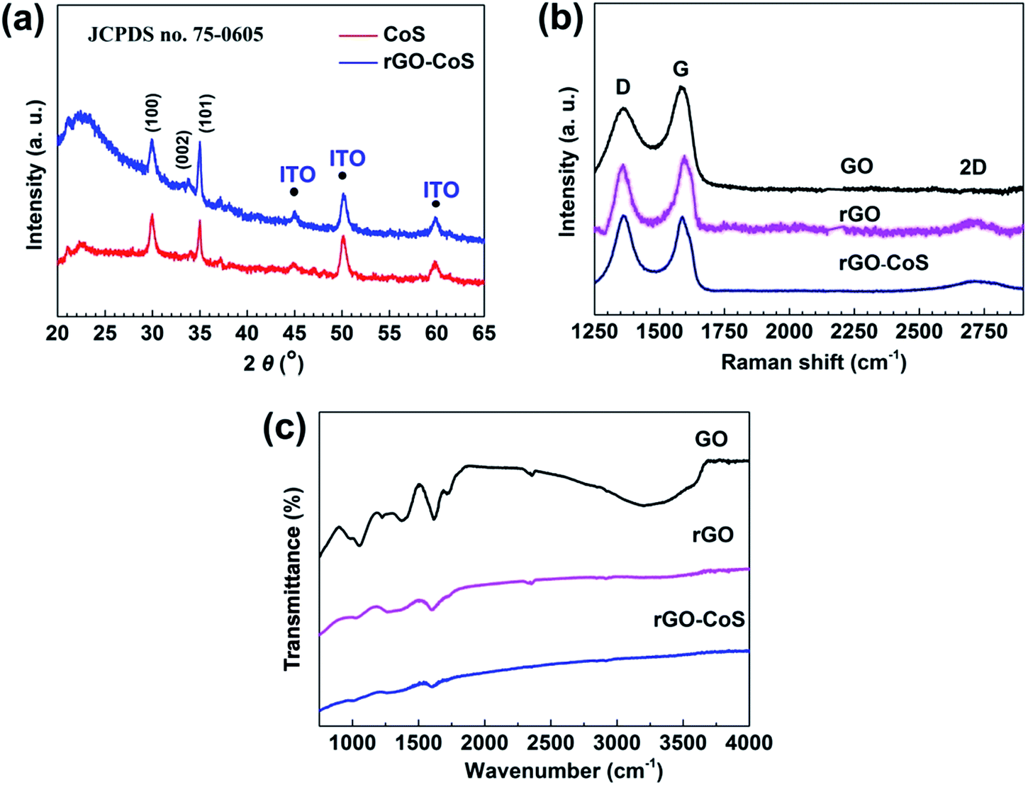
| | Fig. 3 (a) XRD patterns of CoS nanosheet and rGO–CoS nanosheet composite CEs. Both the two CEs have the nearly same diffraction peaks located at 30°, 34°, and 35°, which can be readily indexed to the (100), (002), and (101) planes of the hexagonal phase CoS. (b) Raman spectra of the GO layers, rGO layers, and rGO–CoS nanosheet composite CE. The increase in D/G intensity ratio and the emergence of small 2D peak at around 2750 cm−1 corroborate the presence of rGO in the rGO–CoS composite CE. (c) FT-IR spectra of the GO layers, rGO layers, and rGO–CoS nanosheet composite CE, showing the successful transition from the GO to rGO by electrochemical reduction. | |
The morphology of the rGO–CoS nanosheet composite CEs is shown in Fig. 2b and exhibits 2D nanosheet arrays vertically grown on the rGO/ITO substrates, which is similar to the product directly electrodeposited on bare ITO substrate (Fig. 2a). However, after incorporating the GO layers, the former grew more densely, with smaller interspaces each other and show a distinct decrease in diameter from 0.6–0.8 μm to 0.3–0.4 μm. Besides, it is obvious from the cross section images (Fig. 2c and d) that CoS nanosheet arrays with about 1.4 μm in thickness were vertically electrodeposited on the ITO substrates for pure CoS CE, while hierarchical CoS nanosheet arrays with 5 μm in thickness were observed for rGO–CoS nanosheet composite CEs. The length of an individual CoS nanosheet is about 0.35 μm, consistent with the surface morphology observation in Fig. 2b. Noticeably, this unique structure is conducive to the transport of liquid electrolytes and exhibits larger active surface area for the reduction of I3− ions. Generally, the binding effect existed between the negatively charged oxygen-containing groups on GO surface and the positively charged cations in solution. Therefore, a large number of active sites were provided by the GO layer for the crystal nucleation and growth of CoS nanosheets during the electro-deposition. As a result, smaller-sized, denser CoS nanosheet arrays were formed compared with the products without the incorporation of GO layers. The binding effect also was frequently applied to control the morphology and structure of the products hydrothermally grown on GO layers.31,32 TEM image (Fig. 2e) of rGO–CoS composite film scraped from the substrate displays an individual 2D CoS nanosheet with the same morphology as SEM observation. Ring-like ED patterns (inset of Fig. 2e) of the nanosheet reveal its polycrystalline character. Further high-resolution TEM image of the nanosheets (Fig. 2f) shows that the zone I, II, and III correspond to the (102), (101), and (100) crystallographic planes of CoS, respectively, in good agreement with the polycrystalline conjecture.
Crystal phase of CoS nanosheets and rGO–CoS nanosheets also was confirmed by XRD measurements (Fig. 3a). Both the two CEs have the nearly same diffraction peaks located at 30°, 34°, and 35°, which can be readily indexed to the (100), (002), and (101) planes of the hexagonal phase CoS (JCPDS, PDF no. 75-0605). However, the diffraction peak of graphene at 26° is covered by the broad peak at around 23° for SiO2 in the substrate due to the much smaller quantity of rGO layers compared to the substrate.30 Therefore, Raman spectroscopy was used to further corroborate the presence of rGO in the rGO–CoS composite CE, as shown in Fig. 3b. Two main characteristic peaks at 1356 cm−1 and 1580 cm−1 were observed in all samples, corresponding to the D-band and G-band of polycrystalline graphite,33 respectively. The G-band usually is assigned to the E2g phonons of C sp2 atoms, while the D-band is attributed to the effect of particle size. From Fig. 3b, the D/G intensity ratios of GO and rGO are 0.786 and 0.84 respectively. This change is considered as the formation of more graphitic domains with smaller size upon electrochemical reduction.34,35 Notably, the D/G ratio for the rGO–CoS composite CE is increased further to 1.03, which can be explained by the partial insertion of CoS nanosheets into the GO layers at the beginning of electrochemical process, thus resulting in more disordered carbon structure.31 In addition, the small 2D peak at around 2750 cm−1 was observed for both the rGO and rGO–CoS samples, further demonstrating the existence of rGO.36,37 Fig. 3c presents the FTIR spectroscopy of the GO, rGO, and rGO–CoS composite CEs. Before reduction, the three bands of GO, evident at 1050 cm−1, 1720 cm−1, and 3430 cm−1, are due, respectively, to the C–O (ν(epoxy or alkoxy)), the C![[double bond, length as m-dash]](https://www.rsc.org/images/entities/char_e001.gif) O in the carboxylic acid and carbonyl moieties (ν(carbonyl)), and the O–H stretching mode of intercalated water.34 This result clearly reveals that exfoliated graphite has turned into graphene oxide via Hummer's method. However, in the case of pure rGO and rGO–CoS after electrochemical treatment, the peak at 3430 cm−1 disappears, while other oxygen-containing stretches, such as CO and C–O, also weaken. This result implies that high-purity rGO can be obtained using the electrochemical approach.
O in the carboxylic acid and carbonyl moieties (ν(carbonyl)), and the O–H stretching mode of intercalated water.34 This result clearly reveals that exfoliated graphite has turned into graphene oxide via Hummer's method. However, in the case of pure rGO and rGO–CoS after electrochemical treatment, the peak at 3430 cm−1 disappears, while other oxygen-containing stretches, such as CO and C–O, also weaken. This result implies that high-purity rGO can be obtained using the electrochemical approach.
The electrocatalytic ability and conductivity of pure CoS, rGO–CoS, and Pt CEs were investigated by cyclic voltammetry (CV), electrochemical impedance spectrum (EIS), and the Tafel polarization curve (TPC). From the CV results in Fig. 4a, two pairs of typical oxidation and reduction peaks clearly are observed for each CV curve. The left pair corresponds to the reaction of eqn (1), and the right pair is attributed to the process of eqn (2).38 Note that the left pair of peaks (Ox-1 and Red-1) is the main concerns of our analysis because the function of a DSSC CE is to catalyze the reduction of I3− ions. Generally, the peak current density and the peak-to-peak separation (Epp), which is associated with the reversibility of the redox reaction, are two important parameters for evaluating catalytic activities.39 From Fig. 4a, the rGO–CoS composite CE has the highest peak current density, implying that the electrocatalytic ability of rGO–CoS CE toward I−/I3− is superior to that of pure CoS and even better than that of Pt. In addition, its Epp of 570 mV is lower than 680 mV of CoS. Thus, we confirmed that the rGO–CoS composite CE prepared by the one-step electrochemical method is a remarkable electrochemical catalyst.
 |
| | Fig. 4 (a) CV curves of iodide/triiodide redox species for Pt CE, pure CoS nanosheet CE and rGO–CoS nanosheet composite CE, obtained in ACN solution containing 10.0 mM LiI, 1.0 mM I2, and 0.1 M LiClO4, at a scan rate of 50 mV s−1. (b) Nyquist plots and (c) Tafel polarization curves of Pt, pure CoS nanosheet and rGO–CoS nanosheet composite CEs, obtained with two identical electrodes in the same electrolyte as that used in DSSCs at a scan rate of 10 mV s−1. Inset in (b) gives the equivalent circuit used in DSSCs. | |
EIS represents the intrinsic interfacial charge transfer and charge transport kinetics at the electrode/electrolyte interface.40 It has been tested using symmetric cells fabricated with two identical electrodes. Fig. 4b demonstrates the Nyquist plots of pure CoS, rGO–CoS, and Pt CEs, respectively. The inset shows the equivalent circuit model used for DSSCs. As displayed in Fig. 4b, the high-frequency intercept on the real axis determines the serial resistance (Rs), while two semicircles observed for each curve in the high-frequency (left) and low-frequency (right) regions are assigned, respectively, to the charge-transfer resistance (Rct) at the electrode/electrolyte interface, and the ionic diffusion impedance (ZN) of the I−/I3− redox couple in the electrolyte.41 Table 1 lists the fit data for Rs and Rct. Obviously, the Rs value decreases for the rGO–CoS composite CE compared with pure CoS CE, revealing that the incorporation of rGO layers is beneficial for improving the conductivity of rGO–CoS. Moreover, the rGO–CoS CE has the smallest Rct of 2.1 Ω cm2. The value is slightly lower than that of Pt CE, and only one third of 7.1 Ω cm2 of pure CoS CE. This result suggests that the incorporation of rGO layers can markedly decrease the internal resistance and thus accelerate the reduction process of I3− to I− at the electrode/electrolyte interface. TPC also was conducted on the same symmetric cells used for EIS measurements to further elucidate the catalytic activity for the I3− reduction of Pt, CoS, and rGO–CoS CEs. From Fig. 4c, the rGO–CoS composite CE shows the largest slope of the anodic or cathodic branches around the Tafel zone compared with the Pt and pure CoS CEs, suggesting a higher exchange current density (Jo) on the electrode surfaces.42 Since Jo also is related to the charge-transfer resistance (Rct), it also can be calculated by eqn (3),
| |
 | (3) |
where
R is the gas constant,
F is Faraday's constant,
T is the absolute temperature, and
n is the number of electrons involved with the reduction of I
3−. Accordingly, the calculated
Jo follows the order of rGO–CoS > Pt > CoS, in good agreement with the tendency of the peak current density observed in the CV curves and EIS results.
Table 1 Photovoltaic parameters of the DSSCs assembled with Pt CE, CoS nanosheet CE, and rGO–CoS nanosheet composite CE measured under a light intensity of 100 mW cm−2
| CEs |
Voc (V) |
Jsc (mA cm−2) |
FF |
PCE (%) |
Rs (Ω cm2) |
Rct (Ω cm2) |
| Pt |
0.76 |
16.83 |
0.59 |
7.50 |
3.2 |
2.7 |
| CoS |
0.76 |
13.82 |
0.59 |
6.27 |
3.4 |
7.1 |
| rGO–CoS |
0.77 |
17.02 |
0.63 |
8.34 |
2.2 |
2.1 |
Photocurrent density–voltage (J–V) curves of the DSSCs with pure CoS, rGO–CoS, and commercial Pt CEs were obtained under a light intensity of 100 mW cm−2. A typical schematic configuration of the DSSC is illustrated in Fig. 5a and the J–V curves obtained are shown in Fig. 5b. The inset compares the optical photographs of the rGO–CoS composite CE and pure CoS CE. The photovoltaic parameters are summarized in Table 1. The DSSC with pure CoS CE yielded a PCE of 6.26%, comparable to that obtained in previous research.16 Its photocurrent density (Jsc) is only 13.82 mA cm−2, which is the lowest among the three DSSCs; on the contrary, the Jsc of the DSSC with rGO–CoS composite CE is the highest (17.03 mA cm−2), around 23% increase compared with that of pure CoS-based DSSC. Therefore, the DSSC with the rGO–CoS composite CE achieved an enhanced PCE of 8.34% that is greatly increased by 33% compared with 6.26% of the CoS CE-based DSSC. Noticeably, the enhanced PCE is even superior to 7.5% of Pt CE-based DSSC. This demonstrated the feasibility of using the rGO–CoS CE to supersede the costly traditional Pt CE.
 |
| | Fig. 5 (a) Schematic diagram of a DSSC assembled with the rGO–CoS composite CE. (b) Photocurrent density–voltage (J–V) curves of DSSCs constructed using Pt CE, CoS nanosheet CE and the rGO–CoS composite CE under a simulated solar illumination with a light intensity of 100 mW cm−2 (AM 1.5). Inset in (b) compares the optical photos of pure CoS CE and rGO–CoS composite CE. | |
The outstanding PCE breakthrough is indubitably attributed to the incorporation of conducting rGO layers and the GO layers-induced growth of CoS nanosheet arrays. As displayed in SEM observations, the GO layers-induced growth of CoS exhibits hierarchical structure with smaller nanosheets and denser arrays. This unique structure benefits the transport of liquid electrolytes and provides a larger active surface area on the electrode for the reduction reaction of triiodide ions. Particularly, it is favorable to increase the exchange current density, thus boosting the Jsc value.24,42 Moreover, the incorporation of conductive rGO layers and the optimized CoS nanostructure also greatly decrease the internal resistance of rGO–CoS composite CE (Rs and Rct), as corroborated by the EIS measurements (Table 1). The lowered Rs and Rct of rGO–CoS nanosheets CE could promote the collection of electrons from the external circuit and enhance the charge transfer from the CE to triiodide ions, consequently attributing to the enhancement of FF value.42 In view of these two aspects, the DSSC device based on rGO–CoS nanosheets CE achieves superior photoelectric performance to that based on pure CoS CE.
Since introducing rGO layers can greatly improve the properties of CEs and thus enhance the PCE of DSSCs, the GO loading content on substrates should be a paramount issue in deciding cell performance. Fig. 6a–c demonstrates the compared current–voltage (J–V) characteristics and EIS parameters based on rGO–CoS CEs fabricated by spray-coating GO solutions with different concentrations. All the DSSCs with rGO–CoS composite CEs show higher PCEs compared with the DSSC with pure CoS CE in Fig. 5b. The PCE increased from 7.35% to 8.34% with increasing GO concentration from 0.06 mg mL−1 to 0.09 mg mL−1, and then declines to 7.28% corresponding to concentration of 0.12 mg mL−1. The changes in PCE can be explained by the EIS measurements in Fig. 6b and c, which reveal that the Rs and Rct of rGO–CoS CEs follow the order of 0.12 mg mL−1 > 0.06 mg mL−1 > 0.09 mg mL−1, i.e., totally consistent with the change tendency of PCE. Further AFM investigation (Fig. 6d–f) shows that GO concentration of 0.09 mg mL−1 exhibit a relatively flat morphology, whereas the high-concentration GO solution resulted in wrinkles and stacking, which would increase the serial resistance, as reflected by the EIS results. In turn, the wrinkles and stacking of GO layers also greatly affects the morphology of CoS nanosheet arrays, including their density and size (Fig. 6g–i). Obviously, the CoS nanosheet arrays grown on GO layers with a concentration of 0.09 mg mL−1 exhibits a higher density and smaller size, which would provide a larger surface area for yielding a higher exchange current. The extensive investigation proves that GO layers exert a correlative effect on the resultant DSSC performance.
 |
| | Fig. 6 (a) The photocurrent density–voltage (J–V) curves of DSSCs assembled using the rGO–CoS composite CEs fabricated with GO concentrations of 0.06 mg mL−1, 0.09 mg mL−1, and 0.12 mg mL−1, respectively, under a simulated solar illumination with a light intensity of 100 mW cm−2 (AM 1.5). (b) The EIS spectra of composite CEs were tested at a scan rate of 10 mV s−1 with two identical electrodes in the same electrolyte as that used in DSSCs. (c) The serial resistance (Rs) and charge-transfer resistance (Rct) of composite CEs fabricated with different concentrations of GO. (d–f) AFM images of GO layers fabricated with GO concentrations of 0.06 mg mL−1, 0.09 mg mL−1, and 0.12 mg mL−1, respectively, showing the effect of GO concentration on morphology of GO layers. (g–i) SEM images of the as-prepared rGO–CoS nanosheet arrays directly electrodeposited on the GO layers corresponding to (d–f) counterparts, respectively. | |
Our electrochemical strategy for preparing the rGO–CoS CEs exhibits attractive superiorities compared with other approaches including conventional hydrothermal or CVD methods, as summarized in Table 2. The strategy allows the deposition of CoS nanosheets and the reduction of GO at low temperature, and requires relatively inexpensive equipments. The whole process of fabricating the CEs is facile without additional post-treatments including the doctor-blade or spray-coating procedures.25,42,43 Importantly, it provides a ultrafast route to prepare the rGO–CoS CE only in half an hour, which is several tens of times shorter than the average time (∼15 h) using other approaches (Table 2). Due to the superior electrocatalytic activity, the composite films directly prepared on substrates produced a high PCE of 8.34%, indicating the unparalleled advantages of our electrochemical strategy in preparing the composite CEs. Furthermore, the electrochemical strategy also exhibits its universality in fabricating graphene-enhanced chalcogenide functional composite films. Here, we, for the first time, used the strategy to prepare rGO–MoS2 and rGO–NiS composite CEs12,44 that also exhibited enhanced performances in DSSCs compared with the previous works,24,45,46 as shown in Fig. 7 and Table 3. Similarly, the fabrication process of both the two composite CEs also was ultrafast. Based on the above results, we believe that electrochemical strategy could be a universal method for fabrication of graphene-enhanced chalcogenide functional composite films.
Table 2 Comparison of graphene–CoS composite CEs fabricated by different methods
| Synthesis methods |
Structure |
Heating |
Total time |
PCE (%) |
Ref. |
| CVD/dip-coating/annealing |
Graphene–CoS nanoparticle |
1000 °C |
15 h |
5.04 |
24 |
| Hydrothermal/doctor-blade |
Graphene–CoS nanoparticle |
160–180 °C |
12–18 h |
6.55/7.08 |
25 and 43 |
| Electrophoretic/annealing/solvo-thermal |
Graphene–CoS nanoparticle |
400 °C |
30 h |
5.54 |
27 |
| Hydrothermal/spray-coating/annealing |
Graphene–CoS nanoparticle |
200 °C |
15 h |
7.05 |
42 |
| Spray-coating/electrochemical |
Graphene–CoS nanosheet |
40 °C |
0.5 h |
8.34 |
Our work |
 |
| | Fig. 7 Photocurrent density–voltage (J–V) curves of the DSSCs assembled using (a) rGO–NiS composite CE and pure NiS CE, (b) rGO–MoS2 composite CE and MoS2 CE under a simulated solar illumination with a light intensity of 100 mW cm−2 (AM 1.5). The insets show their optical photos, respectively. | |
Table 3 Comparison of photovoltaic parameters of the DSSCs assembled with rGO–NiS composite CEs and rGO–MoS2 composite CEs fabricated by different methods measured under a light intensity of 100 mW cm−2
| CE |
Synthesis methods |
Voc (V) |
Jsc (mA cm−2) |
FF |
PCE (%) |
Ref. |
| Graphene–NiS |
Spray-coating/electrochemical |
0.73 |
17.00 |
0.63 |
7.77 |
Our work |
| Graphene–NiS |
CVD/dip-coating/annealing |
0.72 |
10.31 |
0.7 |
5.25 |
24 |
| Graphene–MoS2 |
Spray-coating/electrochemical |
0.70 |
17.41 |
0.61 |
7.46 |
Our work |
| Graphene–MoS2 |
Hydrothermal/electrophoretic |
0.77 |
12.79 |
0.59 |
5.81 |
45 |
| Graphene–MoS2 |
Thermal pyrolysis/reduction/drop-casting |
0.73 |
12.51 |
0.66 |
6.04 |
46 |
Conclusions
In conclusion, we presented a facile, low temperature, and ultrafast electrochemical strategy to fabricate the rGO–CoS composite CEs that are low-cost and high-efficiency and can supersede costly traditional Pt CE in DSSCs. In this strategy, electroreduction of original GO layers and electrodeposition of CoS nanosheet arrays was synchronous. It's demonstrated that the incorporation of rGO layers could greatly decrease the charge-transfer resistance and improve the electrocatalytic ability. Furthermore, the GO layers-induced growth of CoS nanosheet arrays with higher density and larger surface area can provide larger surface area for yielding higher exchange current. Thus, the DSSC based on the optimized rGO–CoS composite CEs showed marked enhancement in PCE compared with the previously reported works involved with other fabrication approaches. Further experiments also proved that our electrochemical strategy has potential for further exploiting other graphene-enhanced chalcogenide functional composite films with applications in electronic and optoelectronic devices.
Acknowledgements
This work was supported by the National Basic Research Program of China (973 Program, Grant No. 2015CB352106), the National Natural Science Foundation of China (NSFC, Grant No. 61574034, 51372039, and 51202028), the Jiangsu Province Science and Technology Support Program (Grant No. BK20141118), the Fundamental Research Funds for the Central Universities (Grant No. 2242013R30004), China Postdoctoral Science Foundation Funded Project (Grant No. 2014M550259 and 2015T80480). The work at Brookhaven National Lab is supported by U.S. DOE-BES under Contract number DE-AC02-98CH10886.
References
- W. Q. Wu, H. L. Feng, H. S. Rao, Y. F. Xu, D. B. Kuang and C. Y. Su, Nat. Commun., 2014, 5, 396 Search PubMed.
- S. N. Yun, A. Hagfeldt and T. L. Ma, Adv. Mater., 2014, 26, 6210–6237 CrossRef CAS PubMed.
- F. Xu, J. Chen, X. Wu, Y. Zhang, Y. X. Wang, J. Sun, H. C. Bi, W. Lei, Y. R. Ni and L. T. Sun, J. Phys. Chem. C, 2013, 117, 8619–8627 CAS.
- G. Calogero, P. Calandra, A. Irrera, A. Sinopoli, I. Citro and G. D. Marco, Energy Environ. Sci., 2011, 4, 1838–1844 CAS.
- V. D. Dao, S. H. Kim, H. S. Choi, J. H. Kim, H. O. Park and J. K. Lee, J. Phys. Chem. C, 2011, 115, 25529–25534 CAS.
- J. W. Wan, G. J. Fang, H. J. Yin, X. F. Liu, D. Liu, M. T. Zhao, W. J. Ke, H. Tao and Z. Y. Tang, Adv. Mater., 2014, 26, 8101–8106 CrossRef CAS PubMed.
- Z. Y. Tang, J. H. Wu, M. Zheng, Q. W. Tang, Q. Liu, J. M. Lin and J. L. Wang, RSC Adv., 2012, 2, 4062–4064 RSC.
- M. X. Wu, X. Lin, T. H. Wang, J. S. Qiu and T. L. Ma, Energy Environ. Sci., 2011, 4, 2308–2315 CAS.
- Y. H. Xue, J. Liu, H. Chen, R. G. Wang, D. Q. Li, J. Qu and L. M. Dai, Angew. Chem., Int. Ed., 2012, 51, 12124–12127 CrossRef CAS PubMed.
- S. J. Peng, P. N. Zhu, Y. Z. Wu, S. G. Mhaisalkara and S. Ramakrishna, RSC Adv., 2012, 2, 652–657 RSC.
- J. Kwon, V. Ganapathy, Y. H. Kim, K. D. Song, H. G. Park, Y. Jun, P. J. Yoo and J. H. Park, Nanoscale, 2013, 5, 7838–7843 RSC.
- H. C. Sun, D. Qin, S. Q. Huang, X. Z. Guo, D. M. Li, Y. H. Luo and Q. B. Meng, Energy Environ. Sci., 2011, 4, 2630–2637 CAS.
- Z. Y. Zhang, S. P. Pang, H. X. Xu, Z. Z. Yang, X. Y. Zhang, Z. H. Liu, X. G. Wang, X. H. Zhou, S. M. Dong, X. Chen, L. Gu and G. L. Cui, RSC Adv., 2013, 3, 16528–16533 RSC.
- M. Al-Mamun, H. Zhang, P. Liu, Y. Wang, J. Caoac and H. J. Zhao, RSC Adv., 2014, 4, 21277–21283 RSC.
- J. Y. Lin, J. H. Liao and S. W. Chou, Electrochim. Acta, 2011, 56, 8818–8826 CrossRef CAS PubMed.
- C. W. Kung, H. W. Chen, C. Y. Lin, K. C. Huang, R. Vittal and K. C. Ho, ACS Nano, 2012, 6, 7016–7025 CrossRef CAS PubMed.
- M. K. Wang, A. M. Anghel, B. Marsan, N. C. Ha, N. Pootrakulchote, S. M. Zakeeruddin and M. Gratzel, J. Am. Chem. Soc., 2009, 131, 15976–15977 CrossRef CAS PubMed.
- W. X. Guo, C. Chen, M. D. Ye, M. Q. Lv and C. J. Lin, Nanoscale, 2014, 6, 3656–3663 RSC.
- M. I. Katsnelson, Mater. Today, 2007, 10, 20–27 CrossRef CAS.
- M. Y. Yen, C. K. Hsieh, C. C. Teng, M. C. Hsiao, P. Liu, C. M. Ma, M. C. Tsai, C. H. Tsai, Y. R. Lin and T. Y. Chou, RSC Adv., 2012, 2, 2725–2728 RSC.
- Y. Peng, J. Zhong, K. Wang, B. F. Xue and Y. B. Cheng, Nano Energy, 2013, 2, 235–240 CrossRef CAS PubMed.
- H. Wang and Y. H. Hu, Energy Environ. Sci., 2012, 5, 8182–8188 CAS.
- S. Das, P. Sudhagar, S. Nagarajan, E. Ito, S. Y. Lee, Y. S. Kang and W. B. Choiet, Carbon, 2012, 50, 4815–4821 CrossRef CAS PubMed.
- H. Bi, W. Zhao, S. R. Sun, H. L. Cui, T. Q. Lin, F. Q. Huang, X. M. Xie and M. H. Jiang, Carbon, 2013, 61, 116–123 CrossRef CAS PubMed.
- X. L. Duan, Z. Y. Gao, J. L. Chang, D. P. Wu, P. F. Ma, J. J. He, F. Xu, S. Y. Gao and K. Jiang, Electrochim. Acta, 2013, 114, 173–179 CrossRef CAS PubMed.
- H. W. Hu, J. N. Ding, J. F. Qian, Y. Li, L. Bai and N. Y. Yuan, Mater. Lett., 2014, 114, 7–10 CrossRef CAS PubMed.
- X. H. Miao, K. Pan, G. F. Wang, Y. P. Liao, L. Wang, W. Zhou, B. J. Jiang, Q. J. Pan and G. H. Tian, Chem.–Eur. J., 2014, 20, 474–482 CrossRef CAS PubMed.
- H. C. Bi, K. B. Yin, X. Xie, Y. L. Zhou, N. Wan, F. Xu, F. Banhart, L. T. Sun and R. S. Ruoff, Adv. Mater., 2012, 24, 5124–5129 CrossRef CAS PubMed.
- W. S. Hummers and R. E. Offeman, J. Am. Chem. Soc., 1958, 80, 1339 CrossRef CAS.
- Y. G. Zhou, J. J. Chen, F. B. Wang, Z. H. Sheng and X. H. Xia, Chem. Commun., 2010, 46, 5951–5953 RSC.
- Y. Gu, Y. Xu and Y. Wang, ACS Appl. Mater. Interfaces, 2013, 5, 801–806 CAS.
- Y. Q. Zou and Y. Wang, Nanoscale, 2011, 3, 2615–2620 RSC.
- F. Tuinstra and J. L. Koenig, J. Chem. Phys., 1970, 53, 1126–1130 CrossRef CAS PubMed.
- H. L. Guo, X. F. Wang, Q. Y. Qian, F. B. Wang and X. H. Xia, ACS Nano, 2009, 3, 2653–2659 CrossRef CAS PubMed.
- S. Stankovich, D. A. Dikin, R. D. Piner, K. A. Kohlhaas, A. Kleinhammes, Y. Y. Jia, Y. Wu, S. T. Nguyen and R. S. Ruoff, Carbon, 2007, 4, 1558–1565 CrossRef PubMed.
- A. C. Ferrari, Solid State Commun., 2007, 143, 47–57 CrossRef CAS PubMed.
- A. C. Ferrari, J. C. Meyer, V. Scardaci, C. Casiraghi, M. Lazzeri, F. Mauri, S. Piscanec, D. Jiang, K. S. Novoselov, S. Roth and A. K. Geim, Phys. Rev. Lett., 2006, 97, 187401 CrossRef CAS.
- F. Gong, H. Wang, X. Xu, G. Zhou and Z. S. Wang, J. Am. Chem. Soc., 2012, 134, 10953–10958 CrossRef CAS PubMed.
- J. D. Roy-Mayhew, D. J. Bozym, C. Punckt and I. A. Aksay, ACS Nano, 2010, 4, 6203–6211 CrossRef CAS PubMed.
- X. J. Zheng, J. Deng, N. Wang, D. H. Deng, W. H. Zhang, X. H. Bao and C. Li, Angew. Chem., Int. Ed., 2014, 53, 7023–7027 CrossRef CAS PubMed.
- J. H. Guo, Y. T. Shi, Y. T. Chu and T. L. Ma, Chem. Commun., 2013, 49, 10157–10159 RSC.
- E. B. Bi, H. Chen, X. D. Yang, W. Q. Peng, M. Gratzel and L. Y. Han, Energy Environ. Sci., 2014, 7, 2637–2641 CAS.
- G. Q. Wang, J. Zhang, S. Kuang, S. M. Liu and S. P. Zhuo, J. Power Sources, 2014, 269, 473–478 CrossRef CAS PubMed.
- S. Chen, J. J. Duan, Y. H. Tang, B. Jin and S. Z. Qiao, Nano Energy, 2015, 11, 11–18 CrossRef CAS PubMed.
- J. Y. Lin, C. Y. Chan and S. W. Chou, Chem. Commun., 2013, 49, 1440–1442 RSC.
- C. J. Liu, S. Y. Tai, S. W. Chou, Y. C. Yu, K. D. Chang, S. Wang, F. S. S. Chien, J. Y. Lin and T. W. Lin, J. Mater. Chem., 2012, 22, 21057–21064 RSC.
Footnote |
| † These authors contributed equally to this work. |
|
| This journal is © The Royal Society of Chemistry 2015 |
Click here to see how this site uses Cookies. View our privacy policy here.