DOI:
10.1039/C5RA12541C
(Paper)
RSC Adv., 2015,
5, 81713-81722
Fluorescent nanothermometers based on mixed shell carbon nanodots†
Received
29th June 2015
, Accepted 21st September 2015
First published on 22nd September 2015
Abstract
A novel kind of nanothermometer was prepared, which has potential to monitor the temperature variation in the nano regime. The nanothermometer was based on biocompatible fluorescent carbon nanodots (CDs) via one-step microwave assisted synthesis, and two kinds of polymers, including thermo-sensitive poly(N-isopropylacrylamide) (PNIPAM) and non-thermo-sensitive polyethylene glycol (PEG), were used simultaneously to modify the CDs. Therefore, the as-prepared nanothermometer possesses a CD core and a mixed shell consisting of PEG and PNIPAM chains. The elaborately-designed nanostructure endows the nanothermometer with both temperature sensing capacity and the solution stability. When heating up above the lower critical solution temperature (LCST) of PNIPAM, hydrophobic phase transition occurred to PNIPAM, and the nanothermometer evolved into the core–shell-corona structure, with a freshly-formed and collapsed PNIPAM shell. Meanwhile, the fluorescence behavior of the nanothermometer changed along with the structure transition reversibly without fluorescence decay. The detection temperature of the nanothermometer is consistent with the LCST of the applied thermo-sensitive polymer passivating agents. Moreover, this nanothermometer can remain stable without aggregation and fluorescence quenching whether below or above the LCST due to the stabilizing effect of the PEG chains. Furthermore, the nanothermometer could be endocytosed by cells with negligible cytotoxic effects. In view of the excellent sensitivity and reversibility, preferable biocompatibility as well as nano-scale structure, this nanothermometer shows great potential applications in intracellular imaging and temperature sensing.
Introduction
Temperature is a basic descriptive parameter in physical, chemical and biological fields.1 During physiological processes, minor changes in cellular temperature can reflect accurate and quantitative physical descriptions of cellular events,2 which can be applied to estimate the pathogenesis of certain diseases, such as cancers.3–6 However, in confined nano regimes, there exists unexpected heat transfer, and materials also display especial physicochemical properties.7 Therefore, temperature detection in confined micro-environments is challenging and efforts targeting such challenge have resulted in nanothermometers,8 which can satisfy the requirement for both accuracy and resolution of thermal sensor within spatially localized regions.
Thermo-sensitive polymers, such as poly(N-isopropylacrylamide) (PNIPAM), have been considered as promising candidates to prepare nanothermometers.9–12 Above the lower critical solution temperature (LCST), thermo-sensitive polymers in aqueous solution can undergo a coil-to-globule phase transition due to the destruction of intermolecular hydrogen bonding between polymer chains and water.13 Through incorporating chromophores/fluorophores to thermo-sensitive polymers, the temperature induced morphological transition can be visualized in the fluorescence spectra, which provides a sensitive, selective and real-time detection method for temperature. However, the occurrence of hydrophobic phase transition usually induces aggregation among thermo-sensitive nanomaterials, which might cause quenched fluorescence emission and even interfere the stability of the detection system.
This research demonstrates a stable, sensitive and reversible fluorescent nanothermometer functioning in aqueous media. The structure of such nanothermometer is presented in Fig. 1. Carbon nanodots (CDs) were utilized as the fluorescent source. Compared to traditional fluorescent semiconductor quantum dots (QDs) that compose of heavy metals as the essential photoluminescent elements, CDs are advantageous in their green synthesis and biocompatibility.14,15 Through surface passivation, the fluorescence property of CDs can be effectively improved, and the surface of CDs can be endued with different chemical functional groups. Thermo-sensitive polymer PNIPAM (LCST ca. 32 °C) was applied as both the temperature sensor media and the surface passivating agent for CDs. However, it is noteworthy that, when hydrophobic phase transition of PNIPAM happened above its LCST, CDs passivated with only PNIPAM (PNI–CDs) would aggregate owing to their hydrophobic interaction. In order to improve the stability of PNI–CDs, we chose another non-thermo-sensitive and hydrophilic polymer, polyethylene glycol (PEG), as the co-passivating agent to prepare CDs together with PNIPAM passivating agent. The as-prepared CDs possess a carbon core and a mixed shell that consists of homogeneously mixed PEG and PNIPAM chains. Raising temperature above the LCST of PNIPAM can induce a phase separation between the collapsed hydrophobic PNIPAM chains and the still stretched hydrophilic PEG chains in the mixed shell. At the same time, the CDs with a mixed shell structure (MSCDs) evolve into the CDs with a core–shell-corona structure (CSCCDs). Collapsed PNIPAM chains form a new shell on the carbon core, and flexible PEG corona acts as a hydrophilic protective barrier against aggregation among the CSCCDs. Hydrophobic PNIPAM area can be finely tuned from separate domains to continuous membrane by controlling the relative content of PNIPAM in the mixed shell.16 Moreover, hydrophobic PNIPAM area can be reversibly turned “on” or “off” via switching temperature to regulate the fluorescence behaviour of the MSCDs. On the other hand, through monitoring the fluorescence variation tendency of the MSCDs, environmental temperature can be followed.
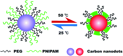 |
| | Fig. 1 Schematic representation of the structure and the functioning mechanism of the fluorescent nanothermometer based on mixed shell carbon nanodots (MSCDs). | |
Material
DL-Alanine (99%), quinine sulfate dehydrate (98%), triethylamine, N-isopropylacrylamide (NIPAM, 98%), azodiisobutyronitrile (AIBN, 98%) and 2-aminoethanethiol (98%) were purchased from Aladdin Industrial Corporation. The reagents in cell experiments were purchased from Dingguo Changsheng Biotechnology Company Limited (Beijing, China). All the other reagents were purchased from Sinopharm Chemical Reagent Company Limited (Shanghai, China). All the solvents were of analytical grade and used as received.
Experimental
Synthesis of passivating agents
Synthesis of PEG–NH2. A solution of p-toluene sulfonyl chloride (PTSC) (1.25 g, 8 mmol) in triethylamine (12 mL) was added dropwise to the solution of CH3–PEG–OH (Mn = 2000, 20.0 g, 10 mmol) dissolved in dichloromethane (CH2Cl2, 100 mL) and stirred at room temperature for 12 hours. The mixture solution was washed with dilute hydrochloric acid (HCl, 1 M, 100 mL × 3); afterwards, sodium carbonate (Na2CO3) was added to the organic layer to neutralize the residual HCl, dried over anhydrous sodium sulfate (Na2SO4), and concentrated under reduced pressure. The product was precipitated with a large excess of cold diethyl ether. Then, the resulting polymer was vacuum dried for 24 hours to obtain the desired CH3–PEG–OTs. Potassium-phthalimide (1.5 g, 8 mmol) was added to a solution of CH3–PEG–OTs (10 g, 2 mmol) in N,N-dimethylformamide (DMF, 40 mL), and the mixture was stirred at 120 °C for 6 hours under nitrogen atmosphere. The reaction mixture was cooled down to room temperature and filtered to remove the insoluble substance. Then, the mixture was poured into a large excess of cold diethyl ether to precipitate the CH3–PEG–NH2. The crude product was redissolved in CH2Cl2, filtered, and precipitated from a large excess of cold diethyl ether; CH3–PEG–NH2 white powders was obtained after drying under vacuum.
Synthesis of PNIPAM–NH2. PNIPAM–NH2 was synthesized by free radical polymerization of NIPAM using AIBN as the initiator and 2-aminoethanethiol as the chain transfer agent. Briefly, the solution of NIPAM (3.39 g, 30 mmol), 2-aminoethanethiol (170.3 mg, 1.5 mmol) and AIBN (0.05 g, 0.3 mmol) in ethanol (50 mL) was mixed under ultrasonic for several minutes. Then the mixture was introduced into the reaction flask and immediately degassed by freeze–thaw cycle. Polymerization was performed at 60 °C under stirring for 24 hours. Subsequently, the reaction mixture was concentrated to 20 mL. KOH ethanol solution (10 mL, 0.15 M) was added to neutralize the residual HCl, and anhydrous Na2SO4 (3 g, 21 mmol) was added to dehydrate. The mixture stood at room temperature for 3 hours and filtered to remove the insoluble substance. The filtrate was poured into a large excess of cold petroleum ether to precipitate the PNIPAM–NH2. The crude product was redissolved in dioxane, filtered, and precipitated from a large excess of cold petroleum ether twice. PNIPAM–NH2 was obtained as white powders after drying under vacuum (yield 75%).
Synthesis of fluorescent carbon nanodots (CDs)
Unpassivated CD (UCD) was prepared from alanine via a one-step NaOH assisted microwave treatment.17 In a typical procedure, 2 g alanine (2 g, 22 mmol) was dissolved in NaOH solution (8 mL, 0.5 M) and then the solution was heated in a domestic microwave oven (700 W) for 2.5 minutes. After cooling, the as-obtained brownish-black solid powder was dissolved with 10 mL ultra-pure water. The supernatant was collected by centrifugation at 12![[thin space (1/6-em)]](https://www.rsc.org/images/entities/char_2009.gif) 000 rpm for 20 minutes and then dialyzed against ultra-pure water through a dialysis membrane (molecular weight cut off = 8000–14000, Shanghai Baoman Biological technology Co. Ltd) for 48 hours to remove the excess precursors and small molecules. The resultant CDs were maintained at 4 °C for further characterization and use. Passivated CDs (PCDs) were prepared through introducing 0.1 mmol polymer passivating agents into the initial alanine NaOH solution. In the preparing process of the MSCD, 0.05 mmol PEG–NH2 and 0.05 mmol PNIPAM–NH2 were added. 0.1 mmol PEG–NH2 and 0.1 mmol PNIPAM–NH2 were separately added to prepare the CD with only PEG or PNIPAM passivated (PEG–CD or PNI–CD).
000 rpm for 20 minutes and then dialyzed against ultra-pure water through a dialysis membrane (molecular weight cut off = 8000–14000, Shanghai Baoman Biological technology Co. Ltd) for 48 hours to remove the excess precursors and small molecules. The resultant CDs were maintained at 4 °C for further characterization and use. Passivated CDs (PCDs) were prepared through introducing 0.1 mmol polymer passivating agents into the initial alanine NaOH solution. In the preparing process of the MSCD, 0.05 mmol PEG–NH2 and 0.05 mmol PNIPAM–NH2 were added. 0.1 mmol PEG–NH2 and 0.1 mmol PNIPAM–NH2 were separately added to prepare the CD with only PEG or PNIPAM passivated (PEG–CD or PNI–CD).
Measurement of fluorescence quantum yields (QY)
The quantum yield of the CDs was determined by a comparative method.18 Quinine sulfate in 0.1 M H2SO4 (literature quantum yield: 54%) was selected as a standard sample to calculate the QY of test sample (i.e. CDs) which was dissolved in ultrapure water at different concentrations. All the absorbance values of the solutions at the excitation wavelength were measured with UV-Vis spectrophotometer. Fluorescence emission spectra of all the sample solutions were recorded by fluorometer at an excitation wavelength of 316 nm. The integrated fluorescence intensity is the area under the fluorescence curve in the wavelength range from 320 to 700 nm. Then a graph was plotted using the integrated fluorescence intensity against the absorbance and a trend line was added for each curve with intercept at zero. Absolute values were calculated according to the following equation| |
 | (1) |
where the subscripts ST and X denote standard and test respectively, Φ is the fluorescence quantum yield, Grad is the gradient from the plot of integrated fluorescence intensity vs. absorbance, and η is the refractive index of the solvent. In order to minimize re-absorption effects, absorbance in the 10 mm fluorescence cuvette should never exceed 0.1 at the excitation wavelength.
Cellular experiments of CDs
The cellular uptake experiments were performed on an inverted fluorescence microscope. BGC-823 cells were seeded into 12-well plates at a density of 105 cells per well in 500 μL RPMI-1640 medium. After an incubation of 24 hours, the culture medium of each well was replaced with 500 μL fresh medium containing 33 μg mL−1 MSCDs. After 24 h of further incubation, the culture medium was removed, and cells were washed three times with 500 μL PBS buffer.
To investigate the cytotoxicity effects of the synthesized MSCDs, the cell viability of BGC-823 cells was measured in the presence of the MSCDs sample. BGC-823 cells were seeded into 96-well plates at a density of 105 cells per well in 100 μL RPMI-1640 medium. After an incubation of 24 hours, the culture medium of each well was replaced with 100 μL fresh medium containing MSCDs of different concentrations. The cells were incubated for another 48 hours. Then, MTT (10 μL, 5 mg mL−1) assays stock solution in PBS was added to each well. After incubating the cells for 4 hours, the medium containing unreacted dye was removed carefully. The obtained blue formazan crystals were dissolved in 120 μL DMSO per well and the absorbance was measured to evaluate the cell viability.
Characterizations
1H NMR spectra were measured with a Varian Mercury 300 NMR spectrometer at room temperature. The gel permeation chromatography (GPC) measurement was conducted with a Waters 1515 GPC instrument equipped with a HT4 and HT3 column (effective molecular-weight range: 5000 to 600000 and 500 to 30000) and a 2414 differential refractive index detector. THF was used as eluent at the flow rate of 1.0 mL min−1 at 30 °C and the molecular weights were calibrated with polystyrene standards. UV-Vis absorption was measured on a Lambda Bio 20 (Perkin-Elmer, America). Fluorescence measurements were performed using F-7000 (FL Spectrophotometer, Japan), equipped with a thermostated cell holder. The excitation and emission slit is 5 and 5 nm, respectively. The normalized spectrum was obtained by dividing each fluorescence intensity of the fluorescence spectrum by the maximum value of its own. The morphology and microstructure of the CDs were examined by high-resolution transmission electron microscopy (HRTEM) on a JEM-2100 (JEOL, Japan) with an accelerating voltage of 200 kV. The samples for HRTEM were made by dropping an aqueous solution onto a 200-mesh copper grid coated with a lacy carbon film. The FTIR spectra of the samples were measured on a Spectra One (Perkin-Elmer, America). The fluorescence lifetime was measured using Fluorolog (Horiba Jobin Yvon) with a TCSPC system. The cellular uptake of MSCDs was observed with an inverted fluorescence microscope (Olympus CKX41, Japan). The absorbance tests in vitro cytotoxicity measurement were carried out in an enzyme-labeled instrument (Tecan Sunrise, Switzerland) at a wavelength of 490 nm.
Results and discussion
Synthesis of polymers
It has been found that the amine molecules play dual functions as N-doping precursors and surface passivation agents for CDs, which can enhance the fluorescence performance of CDs.19 Therefore, in this research, PEG and PNIPAM with a single amino end group were chosen as the polymer passivating agent. The 1H NMR spectra in Fig. 2 indicate the successful amino modification of PEG–OH and synthesis of PNIPAM–NH2. Based on the relative intensities of the characteristic protons, the amino modification ratio of PEG–NH2 can be calculated and reaches to 60.3%, and the polymerization degree of PNIPAM–NH2 is ca. 40. The GPC trace of PNIPAM–NH2 in THF at room temperature is shown in Fig. S1.† The number-average molecular weight (Mn), weight-average molecular weight (Mw) and polydispersity index (PDI) of PNIPAM–NH2 from GPC and 1H NMR tests are listed in Table S1.† Therefore, the two homopolymers are denoted as PEG113–NH2 and PNIPAM40–NH2, respectively. A series of studies indicated that the LCST of PNIPAM could be affected by several factors, including the molecular weight, solvent, concentration, terminal group and so on.20–23 In low molecular weight samples (Mw < 60 kDa), containing significant oligomeric fractions, the slightly hydrophobic methyl propionate end group becomes significant and further decreases the onset temperature of the phase transition.22,23 In high molecular weight samples, there is no effect of molecular weight on LCST. Therefore, controlling the molecular weight of PNIPAM can make vernier adjustment for its LCST.
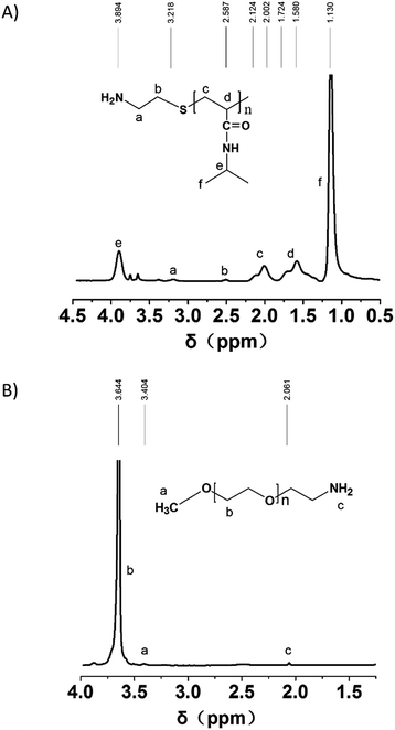 |
| | Fig. 2 1H NMR spectra of PEG–NH2 in (A) CDCl3 and (B) PNIPAM–NH2 in D2O. | |
Formation of MSCDs
The formation of the MSCDs can be confirmed through ultraviolet-visible radiation (UV-Vis), Fourier transform infrared spectroscopy (FTIR), transmission electron microscopy (TEM) and particle size analysis (PSA) tests.
The UV-Vis spectra of CDs in Fig. 3 shows typical optical absorption in the UV region, with a tail extending to the visible range similar to that of previously reported CDs.14 The surface passivation did not shift the absorbance band of CDs. However, the difference between the absorbance curves of UCD and PCDs suggests a successful passivation, as well as the forming of the MSCDs.
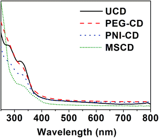 |
| | Fig. 3 Normalized UV-Vis spectra of a series of CDs including UCD, PEG–CD, PNI–CD and MSCD. | |
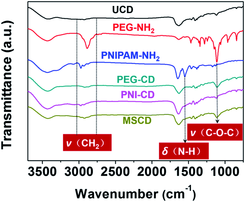
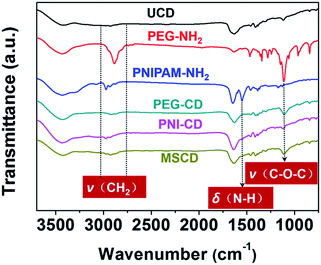
From the FTIR spectra in Fig. 4, the bands of 3000–2850 cm−1 are assigned to the –CH2– vibration. Peaks at 1645, 1550, and 1460 cm−1 are assigned to the amide I (C![[double bond, length as m-dash]](https://www.rsc.org/images/entities/char_e001.gif) O), amide II (N–H) and amide III (C–N) stretching vibrations respectively, which indicate the absence of PNIPAM. The vibrations of C–O–C (1050–1110 cm−1) belongs to PEG. The FTIR spectrum of the MSCD shows both the characteristic vibrations of PEG–CD and PNI–CD, which also confirms the successful preparation of the MSCD.
O), amide II (N–H) and amide III (C–N) stretching vibrations respectively, which indicate the absence of PNIPAM. The vibrations of C–O–C (1050–1110 cm−1) belongs to PEG. The FTIR spectrum of the MSCD shows both the characteristic vibrations of PEG–CD and PNI–CD, which also confirms the successful preparation of the MSCD.
 |
| | Fig. 4 The FTIR spectra of polymer passivating agents and CDs. | |
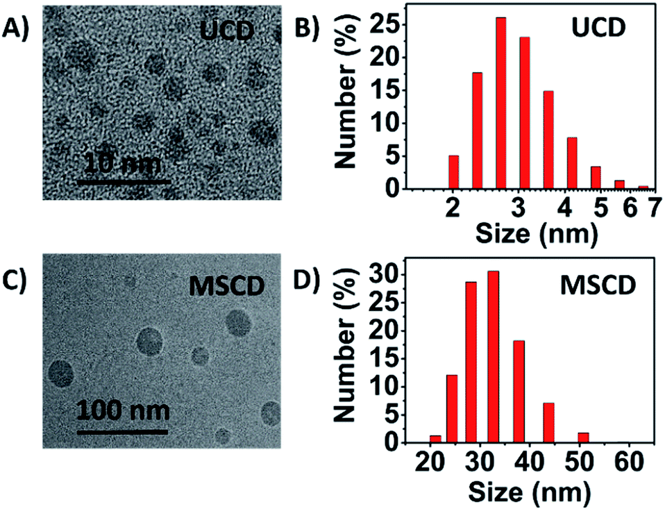
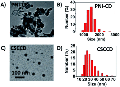
TEM images and size distribution of the UCD and MSCD in Fig. 5 clearly reveal that both UCD and MSCD are well-dispersed with a narrow size distribution at 25 °C. The particle size of the MSCD (ca. 30 nm) is much larger than that of the UCD (ca. 3 nm), which is also larger than that of the previous reported CDs (usually below 10 nm).14 The particle size increase for MSCD can be ascribed to the introduction of PNIPAM passivating agent, which can be concluded from the particle size results of various CDs in Table 1. The particle size of CDs with PNIPAM passivated (including PNI–CD and MSCD) is larger than that of CDs without PNIPAM (including UCD and PEG–CD). There usually exist three steps in the whole forming process of CDs: (i) carbon source dehydration and nanoparticle formation, (ii) surface passivation of nanoparticle and (iii) growth of CDs.24,25 The nature and status of passivating agents will influence the growth of CDs, and then result in CDs with various structure and fluorescence behaviour. During the microwave treatment process of PNI–CD and MSCD, PNIPAM experiences phase transition from hydrophilicity to hydrophobicity with increased temperature, which leads to a distinctive enlarged growing nucleus. The growth of CDs is based on the enlarged nucleus and finally result in the CDs with a larger grain diameter.
 |
| | Fig. 5 (A) TEM image and (B) size distribution of the UCD at 25 °C. (C) TEM image and (D) size distribution of the MSCD at 25 °C. | |
Table 1 The particle diameter of the UCD, PEG–CD, PNI–CD and MSCD
| |
UCD |
PEG–CD |
PNI–CD |
MSCD |
| Particle diameter (nm) |
3.08 |
3.11 |
29.92 |
30.34 |
Fluorescence behaviour of MSCDs
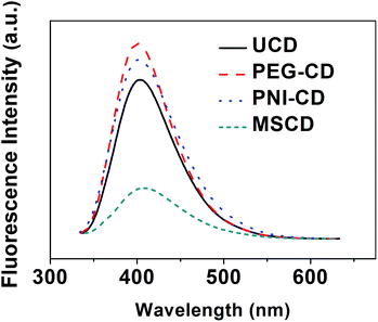
Fig. 6 shows the fluorescence emission spectra of UCD and PCDs upon excitation with the excitation wavelength of 320 nm. As can be seen, aqueous solutions of CDs show a strong fluorescence emission with an emission peak at ca. 400 nm. Using quinine sulfate as the reference, the fluorescence quantum yield (QY) of UCD and PCDs at 25 °C (λex = 320 nm) was checked and listed in Table 2. Compared with the QY of UCD (4.8%), PEG–CD and PNI–CD exhibit a higher QY separately (the QY of PEG–CD and PNI–CD is 6.0% and 5.4%, respectively). However, the QY of MSCD (2.6%) is lower than that of UCD. The fluorescence performance of CDs depends on the preparation conditions.14 The surface passivation with only one polymer passivating agent dose increase the QY of CDs just like the previous studies,14 but to a degree less than what might be expected. On the contrary, the co-passivation process weakens the fluorescence performance of CDs. In the co-passivation process, PEG and PNIPAM passivating agents with different thermodynamic properties21 would compete and participate in the forming and passivation process of MSCD, which brings about a complicated environment unfavorable for the forming and the growth of MSCD. The fluorescent behaviour of the MSCD was also evaluated in various organic solvents, and the QY is listed in Table S2.† Compared with the QY in aqueous phase, that in organic phase is relatively poor, which indicates that the as-prepared nanothermometer is more suitable to function in aqueous phase.
 |
| | Fig. 6 The fluorescence emission spectra (λex = 320 nm) of the UCD, PEG–CD, PNI–CD and MSCD at 25 °C. | |
Table 2 The calculated fluorescence quantum yields (QY) of the UCD, PEG–CD, PNI–CD and MSCD
| |
UCD |
PEG–CD |
PNI–CD |
MSCD |
| QY |
4.8% |
6.0% |
5.4% |
2.6% |
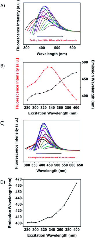
The fluorescence emission spectra of MSCDs excited by various excitation wavelengths are shown in Fig. 7A. With increasing excitation wavelengths, the position of the fluorescence emission peaks for MSCD gradually red-shifted, while the emission peak intensity increased at first and then decreased after reaching a maximum at 330 nm. The excitation wavelength dependence of the emission wavelength and the normalized fluorescence intensity of the maximum MSCD fluorescence emission are shown in Fig. 7B. The excitation wavelength dependence of the emission spectra reflected not only the size effects of CDs but also a considerable distribution of emissive trap sites on each CD.14,15 When the excitation wavelength was increased from 280 to 400 nm, the emission peak of the MSCD red-shifted with ca. 90 nm, while the range of the red-shift was narrow and reached only ca. 60 nm in the cases of the UCD (Fig. 7C and D). The increased red-shift degree in the fluorescence emission of MSCDs further verified that the polymer passivation affected the growth of MSCDs and broadened the size distribution of MSCDs.
 |
| | Fig. 7 The fluorescence emission spectra of (A) MSCD and (C) UCD excited progressively from 280 to 400 nm with 10 nm increments of excitation wavelengths. Excitation wavelength dependence of the emission wavelength and the normalized fluorescence intensity of the maximum (B) MSCD and (D) UCD fluorescence emission. | |
Remarkably, the MSCD was also shown to possess clear upconversion fluorescence properties besides exhibiting strong luminescence in UV-to-near-infrared range. Fig. S2† shows the fluorescence spectra of the MSCD excited by long-wavelength light (from 650 to 850 nm) with the upconverted emissions located in the range from 370 to 580 nm. This upconverted fluorescence property of the MSCD should be attributed to the multiphoton active process similar to previous reported other carbon nanodots.26 These results suggest that the MSCD may also be used as a powerful energy-transfer component in photocatalyst design for applications in environmental and energy issues. Moreover, such spectral working range overlaps spectral ranges in which water absorption vanishes, which is so-called ‘first biological window’ extending from 750 up to 920 nm.27,28 Working in this spectral window does not only reduce excitation and emission-induced heating, but also minimizes light scattering in such a way that the spatial resolution of fluorescent thermal images can be improved.
Thermal sensitivity of MSCD
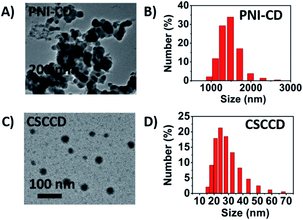
PNIPAM has a hydrophilic amide group and a weak hydrophobic isopropyl group in the side chain. When heating-up above the LCST, the conformation change of the amide groups of PNIPAM leads to a break-up of the hydrogen bond between the amide groups and water molecular. The process of dehydration makes the phase transition of PNIPAM from hydrophilicity to hydrophobicity. In this situation, for PNI-CD with only PNIPAM chains on the surface, the surface turned hydrophobic. PNI–CDs with a hydrophobic surface would aggregate due to their hydrophobic interaction, which can be observed from the TEM images and the size distribution results at 50 °C (Fig. 8A and B). For MSCDs, when hydrophobic PNIPAM chains collapsed on the surface of the CD core and MSCDs evolved into CSCCDs with three-layered structures, the still hydrophilic and flexible PEG chains could act as a protective barrier to stabilize the nanoparticles against aggregation (Fig. 8C and D).
 |
| | Fig. 8 (A) TEM image and (B) size distribution of the PNI–CD at 50 °C. (C) TEM image and (D) size distribution of the CSCCD at 50 °C. | |
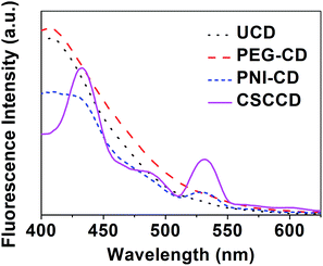
To prove the nanothermometer effect of the MSCD, the fluorescence performance of various CDs was investigated at 50 °C above the LCST of PNIPAM (Fig. 9). The fluorescence emission of the CSCCD at 50 °C is completely different from that of the MSCD at 25 °C. In the fluorescence emission spectrum of the CSCCD, the emission peak of the MSCD at 400 nm disappears and there exist two new emission peaks located at ca. 430 and 530 nm, as well as another weaker shoulder emission peak at ca. 485 nm. For PNI–CD, the fluorescence emission spectrum maintains the main emission peak at 400 nm but its corresponding fluorescence intensity decreases. Meanwhile, a new fluorescence emission peak at ca. 530 nm showed up similar to the fluorescence emission spectrum of the MSCD. The decreased fluorescence intensity can be attributable to the fluorescence quenching caused by the hydrophobic aggregation among PNI–CDs. The fluorescence emission spectra of the UCD and PEG–CD at 50 °C remain the same as that at 25 °C. These results prove that the change in the fluorescence emission spectrum of the CSCCD originates from the temperature-induced structure transition of the MSCD. The collapsed hydrophobic PNIPAM shell created new environment for the CD core, which resulted in the obvious change in the fluorescence emission of the CDs.
 |
| | Fig. 9 The fluorescence emission spectra (λex = 320 nm) of the UCD, PEG–CD, PNI–CD and CSCCD at 50 °C. | |
The temperature response of the PNI–CD and MSCD relies on not only the thermo-sensitivity of PNIPAM, but also the environment-sensitivity of CD. Raising temperature above the LCST induces the transformation of PNIPAM from a swollen hydrated state to a shrunken dehydrated state. The phase transition behaviour of PNIPAM changes the micro-environment of the carbon core and furthermore influences the fluorescence performance. Along with the occurrence of the hydrophobic phase transition, water molecules distributed around the carbon core are token away. Meanwhile, the shrunken PNIPAM chains would package and squeeze the carbon core. These actions synergically function and contribute to the fluorescence emission of the PNI–CD and CSCCD located at ca. 530 nm at 50 °C. Previous studies have also found that some environmental factors, such as pH value, can affect the fluorescence performance of CDs.29,30 For example, the ionization and deionization of exterior carboxyl groups of CDs can affect their water molecules binding ability and fluorescence behaviour. In the presence of PEG, the collapsed PNIPAM induces the surficial phase separation of the MSCD. Hydrophilic PEG chains and hydrophobic PNIPAM chains cooperate and act on the carbon core, and such complicated effect results in the final unique fluorescence emission spectrum of the CSCCD. However, the fluorescence mechanism of CDs is still a matter of dispute and requires further clarification, which might be due to differently sized nanoparticles (quantum effect) and/or different emissive traps on the surface of CDs, or a mechanism currently unresolved.14
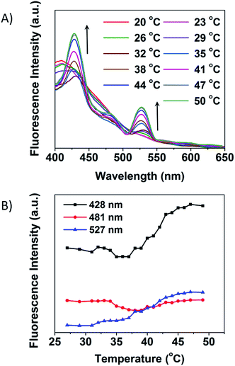
The fluorescence response to temperature of the MSCD can be followed through gradual heating up from 20 to 50 °C (Fig. 10A). The CSCCD shows three main emission peaks at 428, 481, and 527 nm, so we also follow the variation of the emission intensity with temperature at these positions, which is shown in Fig. 10B. From these results, we can see that, around the LCST of PNIPAM, the fundamental change happens in the fluorescence emission spectra, which indicates the structural transition point from the MSCD to the CSCCD. Along with the increase of temperature, the fluorescence intensity of the emission at 428 and 527 nm increase and reach to the equilibrium finally, while that at 481 nm hold the line nearly. Meanwhile, the fluorescence lifetime of the MSCD was also monitored with temperature variation. From the results in Fig. S3,† we can see that, the fluorescence lifetime of the MSCD was shortened as the solution temperature increased. The observation provides adequate evidence that the fluorescence variation indeed originates from the hydrophilic–hydrophobic conversion in microenvironment, which is closely related to temperature. Therefore, the subtle variation can be applied to extrapolate the microenvironment temperature, which makes the MSCD the ideal candidate for nanothermometer. In this system, the emission wavelength at 428 and 527 nm can be applied as the observing points to monitor the temperature variation. The transition temperature of the fluorescence emission spectra keeps pace with the LCST of the thermo-sensitive polymers. Therefore, through selecting thermo-sensitive polymer passivating agents with appropriate LCST, MSCDs can be designed with different responding temperatures. Moreover, through applying the other stimuli-responsive polymer passivating agents to prepare various MSCDs, the response signal can also be changed from the temperature to the other stimuli, such as pH, electric, light, etc.
 |
| | Fig. 10 (A) Overlaid fluorescence spectra of the MSCDs at various temperatures (from 20 to 50 °C, λex = 320 nm). Every spectrum was acquired after reaching equilibrium. (B) Temperature-dependence of the emission intensity of the main peaks located at 428, 481, and 527 nm in the fluorescence spectrum of the CSCCD. | |
The figures of merit of the fluorescent nanothermometer based on the MSCDs were briefly evaluated referring to the related literature.31,32 The fluorescence intensity variation of the emission wavelength located at 428 and 527 nm was applied to make related analysis. The optimal temperature range of operation (ΔT, °C), the maximum relative sensitivity values (Sm, % K−1), the temperature at which Sm is maximum (Tm, °C) and the thermal resolution (R, °C) were calculated and listed in Table 3. During the optimal temperature range of operation, a given fluorescence intensity value matches along with a single temperature value. The relative sensitivity is defined as:
| |
 | (2) |
where
Q corresponds to the quenching of fluorescence with temperature. The
Q values were calculated fitting the experimental data graphically to polynomial interpolations implemented with Origin®. The fitting curves and relative sensitivity figures are provided in the ESI (Fig. S4 and S5
†). A cut-off on the relative sensitivity values is assumed when the absolute temperature resolution Δ
T is below 1 K.
Sm and
Tm represent the maximum value of the relative sensitivity and the temperature at which that value occurs, respectively. The thermal resolution is calculated from the root-mean-square error of the temperature, which is defined as:
| |
 | (3) |
where
T corresponds to the observed temperature, while
T′ corresponds to the predicted temperature. Compared with the other nanothermometers, the nanothermometer based on the MSCDs display a fairly higher relative sensitivity (
Sm = 9.7% K
−1) and thermal resolution (
R < 1 °C).
31,32 However, the optimal temperature range of operation in this system is relatively limited, which needs further improvement.
Table 3 The figures of merit of the fluorescent nanothermometer based on the MSCDs displaying the optimal temperature range of operation (ΔT, °C), the maximum relative sensitivity values (Sm, % K−1), the temperature at which Sm is maximum (Tm, °C) and the thermal resolution (R, °C)
| |
ΔT (°C) |
Sm (% K−1) |
Tm (°C) |
R (°C) |
| 428 nm |
39–45 |
6.1 |
41 |
0.5 |
| 527 nm |
27–45 |
9.7 |
38 |
0.7 |
| I428/I481 |
33–42 |
4.1 |
36 |
0.9 |
| I527/I481 |
31–44 |
12.9 |
33 |
0.7 |
Furthermore, temperature detection through ratiometric fluorescent method was also applied and evaluated in this system. In contrast with single-emission fluorescent probes, a ratiometric fluorescent one can display a self-calibrating readout and overcome difficulties encountered by the conventional fluorescent probes, ultimately providing more robust signals.33–36 Three transition points are used and the ratio between their fluorescent intensities (I428/I481 and I527/I481) is taken as a measurement of the temperature. The fitting curves and relative sensitivity figures are provided in the ESI (Fig. S6 and S7†), and the relative performance index are listed in Table 3. From these results, we can see that, the ratiometric fluorescent method increases the relative sensitivity of this nanothermometer (Sm = 12.9% K−1).
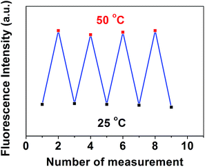
Furthermore, the reversible temperature response of the MSCD was also examined. Fig. 11 shows the multiple-run reversibility experiments of the fluorescence responses to temperature variation for the MSCD. The emission peak located at 530 nm was chosen as the observing point, and the MSCD solution was repeated heating to 50 °C and cooling to 25 °C for four times. No declining signal occurred during multiple-run tests, which indicated the excellent reversibility and stability of the MSCD during the structural transition.
 |
| | Fig. 11 Multiple-run reversibility experiments of the fluorescence responses of the MSCD to temperature variation. | |
Cellular experiments of MSCD
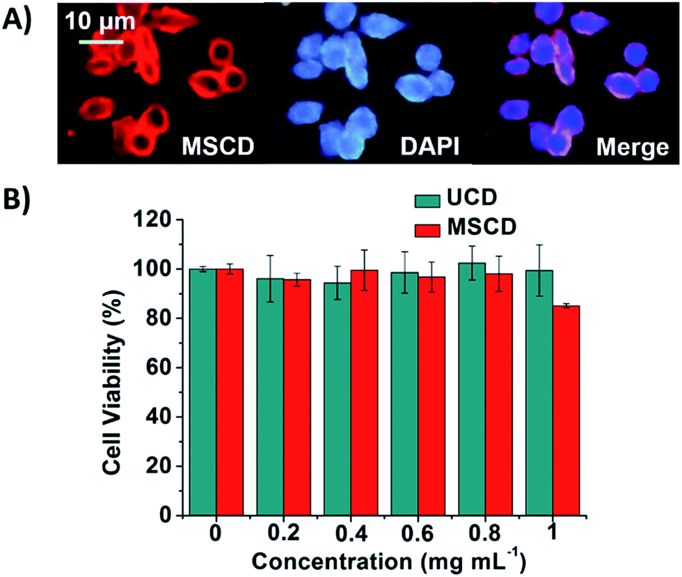
The cellular uptake and the cytotoxic effects were investigated to evaluate the feasibility of applying the MSCD as a nanothermometer to realize intracellular imaging and temperature sensing. To investigate the cellular uptake of the MSCD, BGC-823 cells were incubated with the MSCD at 37.5 °C in RPMI-1640 medium for 24 h. The fluorescent images were presented in Fig. 12A. The MSCD transformed into the CSCCD and showed red fluorescence under the current condition. The nuclei were stained with DAPI, which showed blue fluorescence. The merged image indicated the red CSCCD fluorescence in the cytoplasm surrounding the blue nucleus fluorescence, which confirmed MSCD can be endocytosed by the BGC-823 cells. The MTT assay was also performed to further evaluate the cytotoxic effects of UCDs and MSCDs on BGC-823 cells. The results in Fig. 12B suggested that the cytotoxicity of CDs is negligible up to a concentration of 1 mg mL−1.
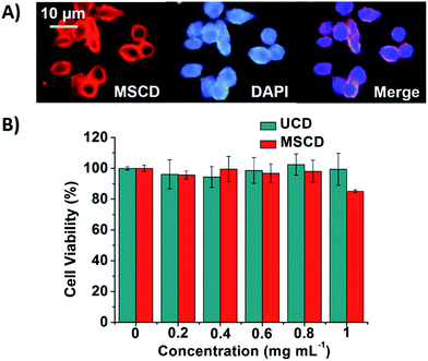 |
| | Fig. 12 (A) Inverted fluorescent microscopy images of BGC-823 cells after incubation with the MSCD at 37.5 °C in RPMI-1640 medium for 24 h. The cell nuclei were stained with DAPI (blue). Scale bar indicates 10 μm. (B) Cytotoxicity of the MSCD at 37.5 °C in RPMI-1640 medium for 48 h determined by MTT assay. | |
Conclusions
This research demonstrates for the first time the feasibility of applying the thermo-sensitive fluorescent MSCD as a nanothermometer. The co-passivation technique is applied to prepare the MSCD with both thermo-sensitive and non-thermo-sensitive polymer as passivating agents. Thermo-sensitive polymer endows MSCD with the ability of temperature sensing capability, while non-thermo-sensitive polymer keeps MSCD stable at elevated temperature. The detection temperature of such nanothermometer can be designed and adjusted through choosing thermo-sensitive polymers with appropriate LCSTs. The excellent sensitivity and reversibility, preferable biocompatibility and nano-scale structure are adequate for intracellular imaging and temperature sensing.
Acknowledgements
The work was financially supported by Natural Science Foundation of China (51403093 and 51373073).
Notes and references
- X. Wang, O. S. Wolfbeis and R. J. Meier, Chem. Soc. Rev., 2013, 42, 7834 RSC.
- B. Hildebrandt, P. Wust, O. Ahlers, A. Dieing, G. Sreenivasa, T. Kerner, R. Felix and H. Riess, Crit. Rev. Oncol. Hematol., 2002, 43, 33 CrossRef.
- M. P. Melancon, M. Zhou and C. Li, Acc. Chem. Res., 2011, 44, 947 CrossRef CAS PubMed.
- R. J. Stafford, A. Shetty, A. M. Elliott, J. A. Schwartz, G. P. Goodrich and J. D. Hazle, Int. J. Hyperthermia, 2011, 27, 782 CrossRef CAS PubMed.
- H. Ishizaka, A. Shiraishi, S. Awata, A. Shimizu and S. Hirasawa, Br. J. Radiol., 2011, 84, 1139 CrossRef CAS PubMed.
- R. J. Leveillee, S. M. Castle, N. Salas, M. Doshi, V. Gorbatiy and W. O'Neill, J. Endourol., 2011, 25, 1119 CrossRef PubMed.
- J. Lee and N. A. Kotov, Nano Today, 2007, 2, 48 CrossRef.
- C. D. S. Brites, P. P. Lima, N. J. O. Silva, A. Millan, V. S. Amaral, F. Palacio and L. D. Carlos, Nanoscale, 2012, 4, 4799 RSC.
- C. Gota, K. Okabe, T. Funatsu, Y. Harada and S. Uchiyama, J. Am. Chem. Soc., 2009, 131, 2766 CrossRef CAS PubMed.
- L. Zhu, W. Wu, M.-Q. Zhu, J. J. Han, J. K. Hurst and A. D. Q. Li, J. Am. Chem. Soc., 2007, 129, 3524 CrossRef CAS PubMed.
- Q. Yan, J. Yuan, Y. Kang, Z. Cai, L. Zhou and Y. Yin, Chem. Commun., 2010, 46, 2781 RSC.
- C.-Y. Chen and C.-T. Chen, Chem. Commun., 2011, 47, 994 RSC.
- R. Liu, M. Fraylich and B. R. Saunders, Colloid Polym. Sci., 2009, 287, 627 CAS.
- S. N. Baker and G. A. Baker, Angew. Chem., Int. Ed., 2010, 49, 6726 CrossRef CAS PubMed.
- H. Li, Z. Kang, Y. Liu and S. T. Lee, J. Mater. Chem., 2012, 22, 24230 RSC.
- R. Ma, B. Wang, Y. Xu, Y. An, W. Zhang, G. Li and L. Shi, Macromol. Rapid Commun., 2007, 28, 1062 CrossRef CAS PubMed.
- J. Jiang, Y. He, S. Li and H. Cui, Chem. Commun., 2012, 48, 9634 RSC.
- A. T. R. Williams, S. A. Winfield and J. N. Miller, Analyst, 1983, 108, 1067 RSC.
- X. Zhai, P. Zhang, C. Liu, T. Bai, W. Li, L. Dai and W. Liu, Chem. Commun., 2012, 48, 7955 RSC.
- M. Heskins and J. E. Guillet, J. Macromol. Sci., Chem., 1968, 2, 1441 CrossRef CAS PubMed.
- F. M. Winnik, H. Ringsdorf and J. Venzmer, Macromolecules, 1990, 23, 2415 CrossRef CAS.
- S. Furyk, Y. J. Zhang, D. Ortiz-Acosta, P. S. Cremer and D. E. Bergbreiter, J. Polym. Sci., Part A: Polym. Chem., 2006, 44, 1492 CrossRef CAS PubMed.
- Y. Xia, X. Yin, N. A. D. Burke and H. D. H. Stöver, Macromolecules, 2005, 38, 5937 CrossRef CAS.
- C. Liu, P. Zhang, X. Zhai, F. Tian, W. Li, J. Yang, Y. Liu, H. Wang, W. Wang and W. Liu, Biomaterials, 2012, 33, 3604 CrossRef CAS PubMed.
- J. K. Kim, S. Y. Yang, Y. Lee and Y. Kim, Prog. Polym. Sci., 2010, 35, 1325 CrossRef CAS PubMed.
- L. Cao, X. Wang, M. J. Meziani, F. Lu, H. Wang, P. G. Luo, Y. Lin, B. A. Harruff, L. M. Veca, D. Murray, S.-Y. Xie and Y. P. Sun, J. Am. Chem. Soc., 2007, 129, 11318 CrossRef CAS PubMed.
- R. R. Anderson and J. A. Parrish, J. Invest. Dermatol., 1981, 77, 13 CAS.
- J. V. Frangioni, Curr. Opin. Chem. Biol., 2003, 7, 626 CrossRef CAS PubMed.
- H. Liu, T. Ye and C. Mao, Angew. Chem., Int. Ed., 2007, 46, 6473 CrossRef CAS PubMed.
- R. Liu, D. Wu, S. Liu, K. Koynov, W. Knoll and Q. Li, Angew. Chem., Int. Ed., 2009, 48, 4598 CrossRef CAS PubMed.
- C. D. S. Brites, P. P. Lima, N. J. O. Silva, A. Millán, V. S. Amaral, F. Palacio and L. D. Carlos, Nanoscale, 2012, 4, 4799 RSC.
- D. Jaque, B. del Rosal, E. M. Rodríguez, L. M. Maestro, P. Haro-González and J. G. Solé, Nanomedicine, 2014, 9, 1047 CrossRef CAS PubMed.
- Y. Shiraishi, R. Miyamoto, X. Zhang and T. Hirai, Org. Lett., 2007, 9, 3921 CrossRef CAS PubMed.
- Y. Shiraishi, R. Miyamoto and T. Hirai, Langmuir, 2008, 24, 4273 CrossRef CAS PubMed.
- D. Wang, R. Miyamoto, Y. Shiraishi and T. Hirai, Langmuir, 2009, 25, 13176 CrossRef CAS PubMed.
- C.-Y. Chen and C.-T. Chen, Chem. Commun., 2011, 47, 994 RSC.
Footnote |
| † Electronic supplementary information (ESI) available. See DOI: 10.1039/c5ra12541c |
|
| This journal is © The Royal Society of Chemistry 2015 |
Click here to see how this site uses Cookies. View our privacy policy here.