DOI:
10.1039/C5RA12530H
(Paper)
RSC Adv., 2015,
5, 73760-73766
Smooth CH3NH3PbI3 from controlled solid–gas reaction for photovoltaic applications†
Received
29th June 2015
, Accepted 20th August 2015
First published on 20th August 2015
Abstract
The merits of high power conversion efficiency (PCE) and easy preparation make organic–inorganic perovskite solar cells one of the most promising solar devices. However, PCE is greatly dependent on the morphology of perovskite thin film. Here, we report a solid–gas reaction method to fabricate very smooth CH3NH3PbI3 thin film with high coverage. Through controlling the reaction rate between CH3NH3I and PbI2 by tuning the PbI2 substrate temperature and the evaporation rate of CH3NH3I, we obtain a CH3NH3PbI3 layer with roughness of 7.37 nm. Besides, no post-treatment annealing is needed after film formation using our approach. With about 250 nm perovskite active layer, the solar cells exhibit a PCE of 10.0% with little hysteresis.
1. Introduction
As one of the emerging and globally investigated solar cells, three-dimensional organic–inorganic perovskite has attracted remarkable attention in recent years for its high absorption coefficient from 300 nm to 800 nm (1.5 × 104 cm−1 at 550 nm),1,2 long exciton diffusion length (1 micrometer for polycrystal3 and 175 micrometers for single crystal4), easy solution process,5–7 and low cost.8 The general chemical formula of perovskite is ABX3 (A = CH3NH3 or HC(NH2)2, B = Pb or Sn, and X = Cl, Br, or I). Through simply varying the elements of A, B, and X, the band gap of perovskite can be easily tuned from 1.3 eV (ref. 9) to 2.3 eV (ref. 10) for wide band absorption of sunlight. With their considerably increasing power conversion efficiency (PCE),6 perovskite solar cells (PSCs) have great potential to approach the theoretical maximum efficiency of 33.7% for single p–n junction solar cells, which was predicted when the band gap of the absorber material was about 1.34 eV.11
The study of three-dimensional organic–inorganic perovskite dates back to several decades ago;12,13 however, not until recently has it been applied in solar cells. In 2006, Kojima and co-workers14 utilized CH3NH3PbBr3 perovskite as sensitizer in solar cells and reported a PCE of 2.19%. After several years of research, the certified efficiency of perovskite solar cells has been improved to 20.1%.15 Despite the exciting progress, there are still some challenges to overcome in practical applications of PSCs. For example, repeatability and stability of perovskite solar cells are not very good. The anomalous hysteresis16 dependent on the scan direction and scan rate of the applied voltage to perovskite solar cells is also a concern. Besides, it is quite difficult to prepare perovskite thin film with full coverage.17 In the conventional one-step solution coating method, perovskite precursor is prepared from a mixture of CH3NH3I and PbI2 (ref. 2) or CH3NH3I and PbCl2 (ref. 3) in dimethylformamide (DMF)6,18,19 or gamma-butyrolactone (GBL)20,21 solvent. The easily obtained morphology with incomplete coverage19,22–25 might be related to the solvent-induced intermediates26 of CH3NH3PbI3·DMF and CH3NH3PbI3·H2O as well as the colloidal nature27 of precursors in solvent, with size ranging from tens of nanometers to micrometers. On the other hand, dual-source vapor deposition22,28 without the use of solvent has been reported to offer quite smooth perovskite thin film with very good coverage. However, the device performance from this approach is very sensitive to the evaporation rates of the two sources. More recently, a vapor-assisted solution process (VASP)29 has been developed; this approach needs a relatively high temperature (150 °C) to sublimate CH3NH3I powder and anneal perovskite thin film. The fabrication of efficient perovskite solar cells at low temperature with smooth morphology and complete coverage is still desired.
Herein, we report a solid–gas reaction method to fabricate CH3NH3PbI3 thin film. The evaporated CH3NH3I molecule interacts upon contact with solid PbI2 spin-coated onto the substrate at 60 °C under vacuum and leads to a compact and smooth thin film with high coverage. No extra annealing is needed after formation of the film. Besides, we find that the solid–gas reaction of PbI2 and CH3NH3I at room temperature is very slow and occurs only at the surface of PbI2. Nevertheless, the PbI2 substrate heated to 60 °C can completely convert PbI2 into CH3NH3PbI3. This can be explained by the improved diffusion rate of CH3NH3I molecules within the PbI2 layer and the increased reaction rate between the solid PbI2 and gaseous CH3NH3I at higher temperature. By optimizing the substrate temperature, CH3NH3I evaporation rate, and PbI2 thickness, we obtain a perovskite thin film of about 250 nm, which gives a PCE of 10.0% with little hysteresis.

2. Experimental
2.1. Materials
Lead(II) iodide (PbI2, 99.9%), N,N-dimethylformamide (DMF, anhydrous, 99.8%), and chlorobenzene (CB, 99.8%) were purchased from Sigma-Aldrich. Isopropanol (IPA, anhydrous, 99.8%) was bought from Acros Organics. PEDOT:PSS (P VP Al 4083) was purchased from Clevios. PC61BM was purchased from Solarmer Energy Inc. Poly[(9,9-bis(3′-(N,N-dimethylamino) propyl)-2,7-fluorene)-alt-2,7-(9,9-dioctylfluorene)] (PFN) was purchased from 1-Material. Methylammonium iodide (CH3NH3I) was synthetized by reacting 13.5 ml methylamine (CH3NH2, 33 wt% in ethanol, Sigma-Aldrich) and 15 ml hydroiodic acid (HI, 57 wt% in water, Sigma-Aldrich) under ice bath for 2 hours. The white precipitate was obtained by removing the solvent using a rotary evaporator at 55 °C. The precipitate was purified by recrystallization, which started with dissolving the precipitate in ethanol followed by adding excess diethyl ether to obtain the precipitate again. The process was repeated for three times. After recrystallization, the precipitate was dried at 60 °C for 24 hours in vacuum.
2.2. Device preparation
The perovskite solar cells have a structure of ITO/PEDOT:PSS (40 nm)/CH3NH3PbI3 (150–250 nm)/PC61BM (50 nm)/PFN (1–2 nm)/Ag (120 nm). ITO substrate was washed successively with deionized water, acetone, and ethanol. After UVO treatment, the ITO substrate was spin-coated with PEDOT:PSS at 4000 rpm for 40 s and annealed at 130 °C for 15 min. PbI2 was dissolved in DMF with concentration of 300 mg ml−1, 462 mg ml−1, and 550 mg ml−1 and stirred at 60 °C for more than 10 hours before use. Yellow PbI2 precursor was spin-coated on PEDOT:PSS at 5000 rpm for 10 s and immediately dried at 90 °C for 15 min (300 mg ml−1 leads to about 60 nm; 462 mg ml−1 leads to about 100 nm; and 550 mg ml−1 leads to about 130 nm). After drying, the samples were mounted on a sample holder and then placed in the vacuum chamber. The PbI2 side of the sample was face down on the CH3NH3I source. The distance between sample and CH3NH3I source was fixed at approximately 30 cm. Besides, the volume of the vacuum chamber was about 58
000 cm3. The chamber pressure was controlled at 10−4 Pa, and the metal sample holder was heated to the desired temperatures of 50 °C, 60 °C, and 70 °C with stability of ±1 °C. The density of CH3NH3I was assumed as 1 g cm−3, as reported by Snaith.22 The evaporation rate was controlled at 0.5 Å s−1, 0.9 Å s−1, and 1.3 Å s−1 via tuning the evaporation current, and it was recorded using Maxtek Model TM-400. After evaporation for 60–80 min, the excess CH3NH3I was washed with IPA. PC61BM (20 mg ml−1 in CB) was spin-coated atop at 1500 rpm, followed by PFN (0.2 mg ml−1 in ethanol) at coating rate of 3000 rpm. Finally, 120 nm Ag was evaporated on PFN at a vacuum pressure of 3 × 10⁻⁴ Pa.
2.3. Characterization
Simulated AM 1.5 sunlight (100 mW cm−2) was generated by the ABET AM 1.5G solar simulator and calibrated using a Hamamatsu silicon reference cell. The current density–voltage curve of CH3NH3PbI3 solar cells was recorded using the Keithley 2635 SourceMeter. Incident photon-to-current efficiency (IPCE) was measured with a home-built system combining a Newport xenon lamp, an Acton monochromator, and a chopper with a Stanford lock-in amplifier. High-resolution scanning electron microscope (SEM) images were obtained using the LEO 1530 FEG SEM. Before SEM measurement, 5 nm gold was evaporated on CH3NH3PbI3 thin film. X-ray diffraction (XRD) spectrum was measured with the Empyrean model from PANalytical equipped with Cu anode material (K-alpha, λ = 1.540598 Å). The generator voltage and current were 40 kV and 40 mA, respectively. Atomic force microscopy (AFM) was performed using a Bruker Veeco Multimode V in trapping mode.
3. Results and discussion
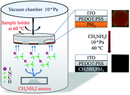
Fig. 1 shows the schematic image of the formation of CH3NH3PbI3 thin film via solid–gas reaction at low temperature under vacuum. Details of the operation conditions can be found in the Experimental section. The evaporated CH3NH3I molecules react with heated PbI2 upon contact and result in the formation of CH3NH3PbI3, which can be preliminarily judged by the color change of the thin film from yellow to dark brown.
 |
| Fig. 1 Schematic image of CH3NH3PbI3 formation via solid–gas reaction at low temperature under vacuum. | |
When the substrate temperature is at room temperature, we observe that the PbI2 substrate after evaporation of excess CH3NH3I is not dark brown, but yellow. However, after heating the substrate to 60 °C during evaporation, the evaporated device becomes dark brown. XRD spectra show the crystalline properties of the PbI2 on substrate and of perovskite from evaporation of CH3NH3I at room temperature and 60 °C, as plotted in Fig. 2. The peaks at 30.27° and 35.08°, marked with blue asterisk, exist in all devices and are assigned to ITO (PDF # 39-1058). Peaks at 12.52°, 25.35°, 38.44°, and 52.12° are observed in the PbI2 samples before CH3NH3I evaporation, which are attributed to the PbI2 crystal (PDF # 07-0235), corresponding to (001) (002), (003), and (004) lattice phases, respectively. After the evaporation of excess CH3NH3I at room temperature and the wash by isopropanol (IPA), peaks at 12.52°, 38.44°, and 52.12° still exist. In addition, new peaks at 14.03°, 28.27°, and 31.74° are observed and assigned to the characteristic peaks of CH3NH3PbI3,30 which means the evaporated samples at room temperature are a mixture of PbI2 and CH3NH3PbI3. On the other hand, for the evaporated samples annealed at 60 °C during evaporation, all peaks assigned to PbI2 disappear, indicating complete conversion of PbI2 into CH3NH3PbI3. This phenomenon should be attributed to the increased diffusion rate of CH3NH3I in the PbI2 layer and the increased reaction rate between CH3NH3I and PbI2 at higher temperature. After getting energy from the heated substrate, CH3NH3I molecules with increased kinetic energy can easily diffuse throughout the PbI2 layer. On the other hand, in terms of chemical kinetics, the reaction rate between CH3NH3I and PbI2 (as described by eqn (1)) is a function of the rate constant and reactants' concentration, as shown in eqn (2),
|
PbI2(s) + CH3NH3I(g) ↔ CH3NH3PbI3(s)
| (1) |
|
ν = κ[CH3NH3I]a[PbI2]b
| (2) |
where
ν is reaction rate,
κ is rate constant, [CH
3NH
3I] is mole concentration of CH
3NH
3I,
a is order in CH
3NH
3I, [PbI
2] is mole concentration of PbI
2, and
b is order in PbI
2.
 |
| Fig. 2 XRD spectrum of PbI2 on ITO/PEDOT:PSS, perovskite on ITO/PEDOT:PSS from room temperature, and perovskite on ITO/PEDOT:PSS from substrate at 60 °C. The peaks marked with blue asterisk at 30.27° and 35.08° were assigned to ITO (PDF # 39-1058). | |
Following the Arrhenius equation, the rate constant κ is dependent on temperature:
where
A is constant,
Ea is activation energy of reaction,
R is the universal gas constant, and
T is temperature.
Referring to eqn (2) and (3), when the temperature is raised, the rate constant κ increases, and thus the reaction rate ν increases. This result also indicates that the reaction between CH3NH3I and PbI2 is endothermic.
3.1. Effects of substrate temperature on perovskite thin film
Substrate temperatures of 50 °C, 60 °C, and 70 °C during evaporation of CH3NH3I were investigated. By studying the absorption spectra of the perovskite film as shown in Fig. 3a, we find that the absorption of perovskite increases with the substrate temperature from 50 °C to 60 °C, which means the crystallization quality of the formed perovskite is better at higher temperature. However, when the substrate temperature is further increased to 70 °C, the absorption decreases. In addition, the color of the perovskite film becomes lighter than perovskite prepared at the substrate temperatures of 50 °C and 60 °C. Two reasons might account for this result.
 |
| Fig. 3 (a) Absorbance of CH3NH3PbI3 thin films and (b) J–V characteristics of CH3NH3PbI3 solar cells prepared from substrate at 50 °C, 60 °C, and 70 °C. | |
First, when the temperature is further increased to higher temperature and reaches 70 °C, it could favour the backward reaction in the reversible reaction31,32 (eqn (1)). In this case, the decomposition rate of CH3NH3PbI3 might increase, and less perovskite will form (and thus the color will become lighter). Another possible reason is that it is thermodynamically unfavorable for CH3NH3I molecules to deposit on hot PbI2 substrate with a temperature of 70 °C. The majority of evaporated CH3NH3I molecules are either evacuated away or deposit on the cold chamber wall. Thus, the formation of perovskite is hindered. A similar phenomenon of degraded perovskite film at a much higher temperature is also observed in the reaction between PbCl2 and CH3NH3I.33 The reduced absorbance of perovskite thin film prepared at a substrate temperature of 70 °C is accompanied by decreased PCE of the corresponding solar cells, specifically, decreased short-circuit current density (Jsc). Fig. 3b shows the current density–voltage plot of perovskite solar cells from the substrate at 50 °C, 60 °C, and 70 °C. The PCE of device increases from 8.37% (Jsc = 11.38 mA cm−2) to 10.00% (Jsc = 14.65 mA cm−2) when increasing substrate temperature from 50 °C to 60 °C, then decreases to 6.33% (Jsc = 10.18 mA cm−2) when the temperature is further improved to 70 °C.
3.2. Effects of CH3NH3I evaporation rate on perovskite film
Based on eqn (2), the reaction rate between PbI2 and CH3NH3I depends on the concentration of CH3NH3I, so we changed the concentration of CH3NH3I by controlling the evaporation rate of CH3NH3I, using the optimized substrate temperature of 60 °C. Evaporation rates of 0.5 Å s−1, 0.9 Å s−1, and 1.3 Å s−1 were investigated. Fig. 4 shows the scanning electron microscope (SEM) and atomic force microscopy (AFM) images of the perovskites prepared from different CH3NH3I evaporation rates. SEM shows that the average diameter of perovskite crystal size increases slightly with increasing evaporation rate. This increased crystal size might be attributed to the improved forward reaction rate of PbI2 and CH3NH3I. Besides, the roughness (Rq) of perovskite films from CH3NH3I evaporation rates of 0.5 Å s−1, 0.9 Å s−1, and 1.3 Å s−1 are 7.37 nm, 10.6 nm, and 16.2 nm, respectively. The increased roughness under higher evaporation rate might be due to uneven nucleation rate. Deposited CH3NH3I reacts with surface PbI2 and leads to primary nucleation of CH3NH3PbI3. At a higher evaporation rate, more CH3NH3I will present at the surface of PbI2, which favours the secondary nucleation of CH3NH3PbI3 on the primary sites. The nucleic sites of big crystal size might grow at higher rates for their larger contact area. As a result, the big crystal will grow even larger, while the growth of small-crystal nucleic sites is diminished. Accordingly, the roughness is enhanced. Nevertheless, under low evaporation rate, the nucleation rate for formation of perovskite seeds is quite uniform over the substrate because no extra CH3NH3I presents at the surface, and newly evaporated CH3NH3I almost equally deposits at each nucleic site. Indeed, the roughness from the evaporation rate of 0.5 Å s−1 is even smaller than that (8.3 nm) of the one with the highest certified perovskite solar cells.34 On the other hand, the lower CH3NH3I evaporation rate of 0.1–0.2 Å s−1 was investigated. However, we find that the color of the device after evaporation of CH3NH3I for more than two hours is slightly brown, which means that a small amount of perovskite has formed. Perovskite solar cells with this thin film exhibit very poor performance (less than 1%). We attribute the result to a too-slow reaction rate between PbI2 and CH3NH3I. The lower CH3NH3I evaporation rate leads to lower concentration of CH3NH3I. Too-low concentration of CH3NH3I diminishes the chance of effective collision between gaseous CH3NH3I molecules and PbI2. According to collision theory,35 effective collision is the premise for two compounds to react with each other. As a result, the formation of perovskite under such condition is quite difficult.
 |
| Fig. 4 (a) High-resolution SEM image, (d) low-resolution SEM image, and (g) AFM image of perovskite thin film from the CH3NH3I evaporation rate of 0.5 Å s−1. (b) High-resolution SEM image, (e) low-resolution SEM image, and (h) AFM image of perovskite thin film from the CH3NH3I evaporation rate of 0.9 Å s−1. (c) High-resolution SEM image, (f) low-resolution SEM image, and (i) AFM images of the perovskite films from the CH3NH3I evaporation rate of 1.3 Å s−1. The size of the AFM image is 5 μm × 5 μm. | |
3.3. Perovskite film from PbI2 with different thicknesses
We have prepared 60 nm and 100 nm thick PbI2 films via spin-coating their precursors with concentrations of 300 mg ml−1 and 462 mg ml−1 in DMF, respectively. After evaporation of excess CH3NH3I with a rate of 0.5 Å s−1 and substrate temperature at 60 °C, the formed perovskite thin films from 60 nm and 100 nm thick PbI2 are measured to about 150 nm and 250 nm using Step Profiler. With these perovskite active layers, the corresponding solar cells exhibit PCEs of 6.49% and 10.0%, respectively (ESI1†). However, we failed to prepare even thicker perovskite from 130 nm PbI2 (from 550 mg ml−1 PbI2 in DMF). Though we evaporated all of the CH3NH3I (1.5 g) that can be stored in our source boat, the conversion of PbI2 into perovskite is not complete, resulting in lower absorption of perovskite thin film and poor performance of the solar cell (less than 2%). We attribute the result to the too-large volume of our vacuum chamber (approximate 58
000 cm3). The utilization of evaporated CH3NH3I in such a big chamber is very low. Most of the CH3NH3I is deposited on the cold wall or evacuated away.
3.4. Photovoltaic performance after post-annealing
Photovoltaic characterization was performed after making 250 nm perovskite film into solar cells. The cross-section SEM image of the cell is shown in Fig. 5a. PEDOT:PSS and PC61BM work as hole transporting layer and electron transporting layer, respectively. PFN36 is used as dipole between PC61BM, and silver cathode to facilitate electron transport. The corresponding energy diagram is shown in Fig. 5b. Post-annealing of deposited perovskite thin film at 100 °C was investigated. Fig. 5c shows the J–V curve of perovskite solar cells from 100 °C with annealing of perovskite thin film for 0 min, 10 min, and 20 min. The Jsc of perovskite solar cells increases with increasing annealing time, which can be explained by the improved crystallization of perovskite thin film. However, it should be noted that annealing at 100 °C, even for 10 min, would reduce the Voc and FF. This phenomenon has also been reported by Ziqi Liang and co-workers.37 The drop of Voc might be due to increased non-radiative recombination centres under annealing at 100 °C.38,39
 |
| Fig. 5 (a) Cross-sectional SEM image of perovskite solar cell. (b) Energy level diagram of the solar cell with structure of ITO/PEDOT:PSS (40 nm)/CH3NH3PbI3 (250 nm)/PC61BM (50 nm)/PFN (1–2 nm)/Ag (120 nm). (c) Current density–voltage curves of perovskite solar cell after 0 min, 10 min, and 20 min post-annealing of perovskite thin films at 100 °C. | |
3.5. Optimized device performances
The champion device without post-annealing has a PCE of 10.0%, Jsc of 14.65 mA cm−2, Voc of 0.93 V, and FF of 0.73 (as shown in Fig. 6a). The Jsc matches well with the value obtained (14.01 mA cm−2) by integrating IPCE, as shown in Fig. 6b. The histograms of Jsc, Voc, FF, and PCE of 20 samples are displayed in Fig. 6c–f. It can be seen that the average PCE is more than 8%. Compared with the reported high-performance CH3NH3Pb(I,Cl)3 solar cell,7,40,41 which contains more than 400 nm active layer, the lower PCE and especially the lower short-circuit current of perovskite solar cells from our approach are mostly attributed to thinner perovskite layer. The large vacuum chamber (approximately 58
000 cm3) in our lab makes the utilization of evaporated CH3NH3I very low, leading to incomplete conversion of thick PbI2 into perovskite even after evaporating all of the CH3NH3I that can be stored in the source boat. As a result, thick perovskite is hard to get under the current condition. However, this issue should not be a problem for vacuum chambers with small volume and large source boat. The hysteresis that occurs in most perovskite devices42–44 is also investigated in our device. The scan rate of our device is 0.13 V s−1, which is slightly lower than the usually reported 0.15 V s−1.42 It is generally accepted that hysteresis is more severe at a lower scan rate.16 Our results are shown in Fig. 6a. It can be seen that the PCEs of our device are very close under forward (PCE = 10.0%) and reverse scan (PCE = 10.3%), which indicates that the hysteresis in our device is very small.
 |
| Fig. 6 (a) Current density–voltage curve and (b) incident photon-to-current efficiency (IPCE) of CH3NH3PbI3 solar cells. (c) Jsc, (d) Voc, (e) FF, and (f) PCE histograms of 20 samples. | |
4. Conclusions
In summary, a solid-evaporated gas reaction method has been developed to fabricate CH3NH3PbI3 perovskite solar cells with very smooth morphology and high coverage. No post-treatment annealing is needed after the film formation in our approach. The smooth morphology originates from the slow reaction of solid PbI2 and diluted gas CH3NH3I molecule and the uniform nucleation rate. Compared with traditional one-step or two-step methods where solvent-induced intermediates might account for the complete coverage, our approach avoids the use of solvent during film preparation and results in high coverage. A PCE of 10.0% and low hysteresis have been achieved using our device. Consequently, this work contributes to the development of low-temperature and simple approaches for fabricating perovskite solar cells.
Acknowledgements
This study is supported by the University Grant Council of the University of Hong Kong (grant 201311159056), the General Research Fund (grants HKU711813 and HKU711612E), the Collaborative Research Fund (grant C7045-14E) and RGC-NSFC grant (N_HKU709/12) from the Research Grants Council of Hong Kong Special Administrative Region, China, and grant CAS14601 from CAS-Croucher Funding Scheme for Joint Laboratories. K. S. would like to acknowledge the financial support of AoE/P-02/12 the Research Grants Council. We thank Paddy K. L. Chan and Zhichao Zhang for help with AFM measurement.
Notes and references
- J. H. Im, C. R. Lee, J. W. Lee, S. W. Park and N. G. Park, Nanoscale, 2011, 3, 4088–4093 RSC.
- H. S. Kim, C. R. Lee, J. H. Im, K. B. Lee, T. Moehl, A. Marchioro, S. J. Moon, R. Humphry-Baker, J. H. Yum, J. E. Moser, M. Gratzel and N. G. Park, Sci. Rep., 2012, 2, 591 Search PubMed.
- S. D. Stranks, G. E. Eperon, G. Grancini, C. Menelaou, M. J. Alcocer, T. Leijtens, L. M. Herz, A. Petrozza and H. J. Snaith, Science, 2013, 342, 341–344 CrossRef CAS PubMed.
- Q. Dong, Y. Fang, Y. Shao, P. Mulligan, J. Qiu, L. Cao and J. Huang, Science, 2015, 347, 967–970 CrossRef CAS PubMed.
- J. Burschka, N. Pellet, S. J. Moon, R. Humphry-Baker, P. Gao, M. K. Nazeeruddin and M. Gratzel, Nature, 2013, 499, 316–319 CrossRef CAS PubMed.
- H. Zhou, Q. Chen, G. Li, S. Luo, T. B. Song, H. S. Duan, Z. Hong, J. You, Y. Liu and Y. Yang, Science, 2014, 345, 542–546 CrossRef CAS PubMed.
- J. H. Im, I. H. Jang, N. Pellet, M. Gratzel and N. G. Park, Nat. Nanotechnol., 2014, 9, 927–932 CrossRef CAS PubMed.
- H. J. Snaith, J. Phys. Chem. Lett., 2013, 4, 3623–3630 CrossRef CAS.
- F. Hao, C. C. Stoumpos, D. H. Cao, R. P. H. Chang and M. G. Kanatzidis, Nat. Photonics, 2014, 8, 489–494 CrossRef CAS PubMed.
- J. H. Noh, S. H. Im, J. H. Heo, T. N. Mandal and S. I. Seok, Nano Lett., 2013, 13, 1764–1769 CrossRef CAS PubMed.
- W. Shockley and H. J. Queisser, J. Appl. Phys., 1961, 32, 510 CrossRef CAS PubMed.
- D. Weber, Z. Naturforsch., 1978, 33, 1443 Search PubMed.
- A. Poglitsch and D. Weber, J. Chem. Phys., 1987, 87, 6373–6378 CrossRef CAS PubMed.
- K. T. A. Kojima, T. Miyasaka and Y. Shirai, presented in part at the 210th ECS Meeting, 2006 Search PubMed.
- http://www.nrel.gov/ncpv/images/efficiency_chart.jpg.
- H. J. Snaith, A. Abate, J. M. Ball, G. E. Eperon, T. Leijtens, N. K. Noel, S. D. Stranks, J. T. W. Wang, K. Wojciechowski and W. Zhang, J. Phys. Chem. Lett., 2014, 5, 1511–1515 CrossRef CAS PubMed.
- G. E. Eperon, V. M. Burlakov, P. Docampo, A. Goriely and H. J. Snaith, Adv. Funct. Mater., 2014, 24, 151–157 CrossRef CAS PubMed.
- P. Docampo, J. M. Ball, M. Darwich, G. E. Eperon and H. J. Snaith, Nat. Commun., 2013, 4, 2761 Search PubMed.
- J. Y. Jeng, Y. F. Chiang, M. H. Lee, S. R. Peng, T. F. Guo, P. Chen and T. C. Wen, Adv. Mater., 2013, 25, 3727–3732 CrossRef CAS PubMed.
- K. T. K. Kojima, Y. Shirai and T. Miyasaka, J. Am. Chem. Soc., 2009, 131, 6050 CrossRef PubMed.
- L. Etgar, P. Gao, Z. Xue, Q. Peng, A. K. Chandiran, B. Liu, M. K. Nazeeruddin and M. Gratzel, J. Am. Chem. Soc., 2012, 134, 17396–17399 CrossRef CAS PubMed.
- M. Liu, M. B. Johnston and H. J. Snaith, Nature, 2013, 501, 395–398 CrossRef CAS PubMed.
- Q. Wang, Y. C. Shao, Q. F. Dong, Z. G. Xiao, Y. B. Yuan and J. S. Huang, Energy Environ. Sci., 2014, 7, 2359–2365 CAS.
- W. Ke, G. Fang, J. Wan, H. Tao, Q. Liu, L. Xiong, P. Qin, J. Wang, H. Lei, G. Yang, M. Qin, X. Zhao and Y. Yan, Nat. Commun., 2015, 6, 6700 CrossRef CAS PubMed.
- B. Conings, L. Baeten, C. de Dobbelaere, J. D'Haen, J. Manca and H. G. Boyen, Adv. Mater., 2014, 26, 2041–2046 CrossRef CAS PubMed.
- F. Hao, C. C. Stoumpos, Z. Liu, R. P. Chang and M. G. Kanatzidis, J. Am. Chem. Soc., 2014, 136, 16411–16419 CrossRef CAS PubMed.
- K. Yan, M. Long, T. Zhang, Z. Wei, H. Chen, S. Yang and J. Xu, J. Am. Chem. Soc., 2015, 137, 4460–4468 CrossRef CAS PubMed.
- O. Malinkiewicz, A. Yella, Y. H. Lee, G. M. Espallargas, M. Graetzel, M. K. Nazeeruddin and H. J. Bolink, Nat. Photonics, 2013, 8, 128–132 CrossRef PubMed.
- Q. Chen, H. P. Zhou, Z. R. Hong, S. Luo, H. S. Duan, H. H. Wang, Y. S. Liu, G. Li and Y. Yang, J. Am. Chem. Soc., 2014, 136, 622–625 CrossRef CAS PubMed.
- A. Mei, X. Li, L. Liu, Z. Ku, T. Liu, Y. Rong, M. Xu, M. Hu, J. Chen, Y. Yang, M. Gratzel and H. Han, Science, 2014, 345, 295–298 CrossRef CAS PubMed.
- Q. Chen, H. P. Zhou, T. B. Song, S. Luo, Z. R. Hong, H. S. Duan, L. T. Dou, Y. S. Liu and Y. Yang, Nano Lett., 2014, 14, 4158–4163 CrossRef CAS PubMed.
- Y. Jin and G. Chumanov, Chem. Lett., 2014, 43, 1722–1724 CrossRef.
- C. W. Chen, H. W. Kang, S. Y. Hsiao, P. F. Yang, K. M. Chiang and H. W. Lin, Adv. Mater., 2014, 26, 6647–6652 CrossRef CAS PubMed.
- N. J. Jeon, J. H. Noh, Y. C. Kim, W. S. Yang, S. Ryu and S. I. Seok, Nat. Mater., 2014, 13, 897–903 CrossRef CAS PubMed.
- P. Atkins and J. d. Paula, Physical Chemistry, Oxford University, Great Britain, 8th edn, 2006, part 3, pp. 807–871 Search PubMed.
- F. X. Xie, D. Zhang, H. Su, X. Ren, K. S. Wong, M. Gratzel and W. C. Choy, ACS Nano, 2015, 9, 639–646 CrossRef CAS PubMed.
- Y. N. Chen, Y. X. Zhao and Z. Q. Liang, Chem. Mater., 2015, 27, 1448–1451 CrossRef CAS.
- W. Tress, N. Marinova, O. Inganäs, M. K. Nazeeruddin, S. M. Zakeeruddin and M. Graetzel, Adv. Energy Mater., 2015, 5, 1400812 Search PubMed.
- J. Yao, T. Kirchartz, M. S. Vezie, M. A. Faist, W. Gong, Z. He, H. Wu, J. Troughton, T. Watson, D. Bryant and J. Nelson, Phys. Rev. Appl., 2015, 4, 014020 CrossRef.
- W. Y. Nie, H. H. Tsai, R. Asadpour, J. C. Blancon, A. J. Neukirch, G. Gupta, J. J. Crochet, M. Chhowalla, S. Tretiak, M. A. Alam, H. L. Wang and A. D. Mohite, Science, 2015, 347, 522–525 CrossRef CAS PubMed.
- N. Ahn, D. Y. Son, I. H. Jang, S. M. Kang, M. Choi and N. G. Park, J. Am. Chem. Soc., 2015, 137, 8696–8699 CrossRef CAS PubMed.
- W. Zhang, M. Saliba, D. T. Moore, S. K. Pathak, M. T. Horantner, T. Stergiopoulos, S. D. Stranks, G. E. Eperon, J. A. Alexander-Webber, A. Abate, A. Sadhanala and S. P. H. J. Snaith, Nat. Commun., 2015, 6, 6142 CrossRef CAS PubMed.
- W. Tress, N. Marinova, T. Moehl, S. M. Zakeeruddin, M. K. Nazeeruddin and M. Grätzel, Energy Environ. Sci., 2015, 8, 995–1004 CAS.
- Y. Shao, Z. Xiao, C. Bi, Y. Yuan and J. Huang, Nat. Commun., 2014, 5, 5784 CrossRef CAS PubMed.
Footnote |
† Electronic supplementary information (ESI) available. See DOI: 10.1039/c5ra12530h |
|
This journal is © The Royal Society of Chemistry 2015 |
Click here to see how this site uses Cookies. View our privacy policy here.