Microphase separated sepiolite-based nanocomposite blends of fully sulfonated poly(ether ketone)/non-sulfonated poly(ether sulfone) as proton exchange membranes from dual electrospun mats

Maryam Oroujzadeh, Shahram Mehdipour-Ataei* and Masoud Esfandeh
Iran Polymer and Petrochemical Institute, P.O. Box 14965/115, Tehran, Iran. E-mail: s.mehdipour@ippi.ac.ir

Received 25th June 2015 , Accepted 12th August 2015

First published on 12th August 2015


Abstract

In this study, nanocomposite blends of fully sulfonated poly(ether ketone) (PEK) and non-sulfonated poly(ether sulfone) (PES) were prepared from a dual electrospinning process. Sepiolite was used as the nanoparticle and was dispersed only in the non-sulfonated PES matrix to avoid the barrier effects of nanoparticles against protons in these proton exchange membranes. As a novel and special technique, using this dual electrospinning process and melting only in the non-sulfonated sepiolite dispersed fibers resulted in membranes in which ionic paths (fibers of fully sulfonated PEK) were embedded in a sepiolite dispersed non-ionic matrix. The presence of these ionic channels was proved by transmittance electron microscopy (TEM) with staining. The thermal and mechanical properties and the water absorption, dimensional stability, and proton conductivity of these hydrophilic/hydrophobic phase separated membranes were measured and investigated for samples with different sepiolite and sulfonated fiber contents.

1. Introduction

Recently, the introduction of nanoparticles into proton exchange membranes has attracted considerable attention, and a great number of inorganic nanoparticles of different shapes and types have been studied.1,2 In general, the objectives of adding nanoparticles to the polymeric matrix of proton exchange membranes are improving mechanical strength and dimensional and thermal stability of the membrane and also decreasing the water absorption and methanol permeability (for direct methanol fuel cells) of the prepared membranes.3–5 However, this strategy suffers from some disadvantages. One of the main drawbacks of using nanoparticles in proton exchange membranes is that the nanoparticles act as a physical barrier against proton transportation and decrease the proton conductivity of the resulting membrane.6–8

Moreover, the challenge of finding an alternative membrane for Nafion in fuel cell applications is of increasing importance because Nafion membranes have some disadvantages such as instability at temperatures above 80 °C or high methanol crossover in direct methanol fuel cells.9–13 However, in most introduced alternative polymers, the proton conductivity values are not as high as the proton conductivity of Nafion membranes; this is attributed to the difference between the microstructure of Nafion membranes and that of the alternative aromatic polymers. It has been proved that the separated hydrophilic/hydrophobic microstructure in Nafion membranes is larger than that in alternative aromatic polymers, and this is the main reason for the greater efficiency of proton transfer in Nafion membranes.14 Therefore, different techniques, such as synthesis of block copolymers or polymers with accumulations of sulfonic acid groups in some parts of the chain, have been used to improve the microphase separation and consequently the proton conductivity of these alternative membranes.15–24

In the present study, the authors had two main purposes. The first is the formation of hydrophilic/hydrophobic separated regions in the structure of proton exchange membranes by producing ionic paths in a totally hydrophobic matrix by a novel technique using dual electrospinning. In the electrospinning process, an electrical charge is used to draw submicron fibers from a polymeric solution with a specific concentration and in the dual electrospinning process, two polymeric solutions are electrospun simultaneously.

The other purpose is the introduction of inorganic nanoparticles into the structure of the membranes without any negative effects on the proton conductivity of the resulting membranes. Sepiolite was used as the nanoparticle in this investigation. Sepiolite is a fibrous magnesium silicate with the unit cell formula of Si12O30Mg8(OH)4(H2O)4·8H2O and a large surface area.25,26

The base polymers of the blend membranes in this investigation were fully sulfonated PEK and non-sulfonated PES both of which were synthesized in our laboratory. The membranes were prepared by dual electrospinning of these two polymers. To introduce the sepiolite nanoparticles into the polymeric matrix, they were dispersed in a solution of non-sulfonated PES before the electrospinning process. Then, this nano-dispersed solution of non-sulfonated PES was electrospun simultaneously with fully sulfonated PEK.

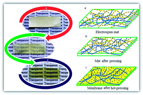
In this way, electrospun mats consisting of fully sulfonated PEK fibers and non-sulfonated PES fibers containing dispersed nanoparticles were prepared. Due to the presence of sulfonated groups in every repeating unit of the fully sulfonated PEK fibers, the two mentioned polymeric fibers had noticeably different melting points. This difference resulted from the fact that ionic structure increases the melting or softening point of sulfonated PEK in comparison to the non-sulfonated PES fibers. By applying a hot-press technique at certain temperatures, the fibers of the non-sulfonated PES containing nanoparticles were melted and covered the fully sulfonated fibers of PEK as a matrix. Thus, nanocomposite blend proton exchange membranes composed of ionic channels of PEK in a PES matrix containing sepiolite nanoparticles were obtained.

2. Experimental

2.1. Materials

4,4′-Difluorobenzophenone (DFB) and bis-(4-chlorophenyl sulfone) (BCPS) as dihalide monomers (both from Aldrich) were recrystallized from toluene before use. 4,4′-(1,4-Phenylene diisopropylidene) bisphenol (PBP) as a dihydroxy monomer (from Aldrich) was recrystallized from xylene. Potassium carbonate (from Merck) was dried at 120 °C in a vacuum oven overnight. Dimethyl acetamide (DMAc) (from Merck) was dried over calcium hydride for 12 h and then distilled under reduced pressure and stored over molecular sieves. Ethanol, toluene, xylene, tetrahydrofuran (THF), dimethylformamide (DMF), 2-propanol, and fuming sulfuric acid (30%) (all from Merck) were used as received.

2.2. Synthesis of sulfonated monomers and related sulfonated and non-sulfonated polymers

The syntheses of sulfonated DFB and PEK were performed according to a procedure reported previously.27 The condensation polymerization of sulfonated DFB (sDFB) as a dihalide monomer and PBP as a dihydroxy monomer resulted in fully sulfonated PEK. Non-sulfonated PES was synthesized from the condensation polymerization of BCPS as a dihalide monomer and PBP as a dihydroxy monomer. Both condensation polymerizations were performed in the presence of potassium carbonate in DMAc and toluene as solvents. A representative procedure for the synthesis of non-sulfonated PES is as follows:

1.4358 g of BCPS and 1.7323 g of PBP were added to a three necked flask equipped with a nitrogen inlet and a Dean–Stark trap. After 16 ml of DMAc and 8 ml of toluene were added, the mixture was heated to 140 °C. The mixture was refluxed for 4 h, and the temperature was increased to 175 °C until the reaction was complete. Furthermore, the resulted viscous non-sulfonated PES was poured into excess amounts of deionized water after dilution with DMAc and stirred for 24 h to remove any remaining salts. Then, the resulting fibrous polymer was dried at 120 °C in a vacuum oven.

2.3. Dispersion of sepiolite nanoparticles in non-sulfonated PES solution

Non-sulfonated PES was dissolved in a 50[thin space (1/6-em)]:[thin space (1/6-em)]50 mixture of DMF/THF as solvent (10 wt%) and then specific amounts of sepiolite nanoparticles were added to the solution. After 20 minutes of stirring followed by 20 minutes of sonication of the solution in an ice bath, the nanoparticle dispersed solutions were prepared for electrospinning. Two solutions with concentrations of 4 and 8 wt% nanoparticles in the non-sulfonated PES polymer were prepared in this step.

2.4. Dual electrospinning of synthesized polymers

Sepiolite dispersed non-sulfonated PES solution and fully sulfonated PEK solution were electrospun simultaneously. To prepare the proper fibers and mats in the electrospinning process, various solvents were tested and as mentioned above, a 50[thin space (1/6-em)]:[thin space (1/6-em)]50 mixture of DMF/THF for non-sulfonated PES and DMF for fully sulfonated PEK was selected.

Other electrospinning parameters, such as concentration of the polymer solutions, flow rates, applied voltage, needle to collector distance, and collector rotation speed, were optimized for both fully sulfonated PEK and sepiolite dispersed non-sulfonated PES to determine the best conditions for producing fibers without beads or defects. As a result, for dual electrospinning of 10 wt% of nanoparticle dispersed non-sulfonated PES in a 50[thin space (1/6-em)]:[thin space (1/6-em)]50 mixture of DMF/THF and also electrospinning of 25 wt% of fully sulfonated PEK in THF, the other parameters were as follows: applied voltage of 27 kV, needle to collector distance of 15 cm, collector rotating speed of 700 rpm, and collector reciprocal motion speed of 8.8 mm s−1. However, the flow rates for fully sulfonated PEK and non-sulfonated PES polymer solutions were 0.2–0.3 and 0.9–1.3 ml h−1, respectively. Each sample was electrospun for 4.5 h.

For preparing mats with different degrees of fully sulfonated PEK fibers, two series of mats with 35 and 55 wt% of sulfonated fibers and two series with different nanoparticle contents (4 and 8 wt%) were prepared. For comparison, two mats without any sepiolite nanoparticles were also prepared. In this way, 6 series of mats were electrospun in this investigation.

2.5. Processing of the electrospun mats

As shown schematically in Fig. 1, the porous structure of the mats prepared from the dual electrospinning process (Fig. 1a) was converted to suitable proton exchange membranes for fuel cell applications via the following procedure: firstly, the blend nanocomposite mats were compressed under a pressure of 125 kg cm−2 for 10 seconds at room temperature to form packed fiber mats (Fig. 1b). In this step, the thickness of the mat was reduced to half. Then, these compressed mats were hot-pressed at a pressure of 125 kg cm−2 and a temperature of 220 °C for 15 seconds (Fig. 1c). This step was repeated three times with rotation of the mats. Using this method, the fibers of non-sulfonated PES containing sepiolite nanoparticles were melted and flowed between the fully sulfonated PEK fibers via hot-pressing without damaging the structure of the sulfonated fibers. The heat and pressure in this step caused fusion only between the fully sulfonated PEK fibers and resulted in an interconnected network for proton transportation. By dispersing sepiolite in a non-sulfonated solution and hot-pressing the electrospun mats, the nanoparticles were only dispersed in the non-sulfonated matrix and did not enter the network of fully sulfonated fibers. Thus, dispersing the nanoparticles in this way had no negative effect on the proton conductivity of the final membranes. Finally, six series of membranes with different contents of fully sulfonated PEK fibers (35 and 55 wt%) and different contents of sepiolite nanoparticles (4 and 8 wt%) were prepared by this method. It should be noted that unlike other previously reported studies of fuel cell applications, in which the electrospinning process was simply used as a technique for preparing membranes or hybrid membranes,28–34 in this research, the process was used to induce separated hydrophilic/hydrophobic regions in the structure of the membrane.
image file: c5ra12335f-f1.tif
Fig. 1 Schematic of the prepared electrospun mats (a), the mats after pressing (b), and the membranes after hot-pressing (c); synthesis of fully-sulfonated PEK (d) and non-sulfonated PES (e).

The final step in preparing these blend nanocomposite membranes was converting the sulfonate groups from the salt to acid form in the PEK fibers. To achieve this, the membranes were immersed in 4 M H2SO4 solution for 24 h to convert the potassium salt form of the ionic groups of the PEK fibers to sulfonic acid groups. Then, the membranes were immersed in deionized water for 24 h to remove the excess acid. Afterwards, all the membranes were vacuum dried at 60 °C for 12 h.

2.6. Measurements

For characterization of the sulfonated monomer (sDFB), 1H-NMR (Bruker Avance DPX 400 MHz) and FT-IR (Bruker-IFS48) spectroscopy were used; the results were reported previously.27 The structures of fully sulfonated PEK and non-sulfonated PES were also confirmed with FT-IR spectroscopy.

The number average molecular weights of the synthesized sulfonated PEK and PES were determined by gel permeation chromatography (GPC-Waters chromatograph) with polystyrene standards in DMF and also THF as eluent.

Thermogravimetric analysis (TGA) from room temperature to 650 °C at a heating rate of 10 °C min−1 in air atmosphere was performed with a Mettler TGA/DSC 1 and was used to determine the thermal stability of the prepared membranes.

Scanning electron microscopy (SEM) was applied to study the morphology of the electrospun fibers and prepared mats using a VEGA TESCAN at an accelerating voltage of 20 kV. The elemental map of Si was used to study the probability of the presence of nanoparticle agglomerations by performing energy dispersive X-ray analysis (EDXA).

Transmittance electron microscopy (Philips S-208 TEM microscope) was used to confirm the presence and dispersion of sepiolite nanoparticles in nanocomposite blend membranes. Moreover, TEM with staining was used to prove the existence of fully sulfonated PEK as fibers after the hot-pressing step. AgNO3 solution was used to stain the samples.

The ion exchange capacity (IEC) of the membranes was determined via a routine titration method. 0.06 g of membrane samples were immersed in 2 M NaCl solution for 24 h. After the H+ ions were replaced with Na+, the liberated H+ ions were titrated with a 4 mM NaOH solution. Phenolphthalein was used as the indicator for titration and at least three measurements were performed for each sample. The following equation was used to calculate the IEC values:

image file: c5ra12335f-t1.tif
where VNaOH and MNaOH are the volume and concentration of the NaOH solution, respectively.

The water absorption of the prepared membranes was measured as the increase in weight of the dry samples after immersing them in deionized water for 24 h. To determine the amount of water absorption over time, the test was continued for 750 h. The following equation was used to determine the water absorption values:

image file: c5ra12335f-t2.tif
where Ww and Wd are the wet and dry weights of the membrane samples, respectively.

The dimensional stability of the nanocomposite blend membranes was measured from the swelling ratio of the membranes. The lengths of the samples in their dry and wet states were determined and their swelling percentages were calculated by the following equation:

image file: c5ra12335f-t3.tif
where Ld is the length of the dry membrane and Lw is the length of the membrane in the wet state.

Proton conductivity measurements were performed by electrochemical impedance spectroscopy (EIS) in a homemade cell using an Autolab PGSTAT 30 with an AC amplitude of 50 mA ranging from 1 to 106 MHz in the lateral direction at room temperature and also at 80 °C in water. The nanocomposite blend membranes were fully hydrated for 24 h before these measurements. The resistance of the membrane was determined at the frequency that produced the minimum imaginary response. The proton conductivity was calculated using the following equation:

image file: c5ra12335f-t4.tif
where L is the distance between two electrodes, R is the membrane resistance and A is the membrane cross-sectional area.

The mechanical strength of the membranes was determined from tensile tests using a STM-20 tester according to ASTM-D 882 at a speed of 5 mm min−1 at room temperature. 50 mm × 10 mm rectangular samples were used. At least 3 samples were tested for each measurement. To study the effects of hydration on the mechanical properties, the tensile strength of the membranes after 24 hours of immersion in water were measured as well.

3. Results and discussion

3.1. Synthesis and characterization of sulfonated monomer, fully sulfonated PEK, and non-sulfonated PES

sDFB as a sulfonated monomer was synthesized via an electrophilic aromatic sulfonation reaction that was reported previously. FT-IR and 1H-NMR spectroscopy confirmed the successful synthesis of the monomer and its purity.27

Fully sulfonated PEK and non-sulfonated PES polymers were synthesized by the condensation polymerization of stoichiometric amounts of sDFB as a dihalide and PBP as a diol monomer (Fig. 1d), as well as BFPS and PBP monomers (Fig. 1e), respectively.

FT-IR spectroscopy confirmed the structures of the synthesized polymers. Characteristic bands for non-sulfonated PES at 1160 and 1323 cm−1 were observed and are attributed to the sulfone functional groups. For fully sulfonated PEK, peaks at 1029 and 1085 cm−1 were observed, related to the sulfonic acid groups, and the characteristic band for the carbonyl group at 1661 cm−1 was also observed. Characteristic bands for ether linkages and aliphatic hydrogens at 1246 and 2967 cm−1, respectively, were observed for both polymers.35

Gel permeation chromatography was used to determine the number average molecular weights to confirm the successful synthesis of the polymers. The resulting number average molecular weights for fully sulfonated PEK and non-sulfonated PES were 58.000 and 83.000 g mol−1, respectively.

3.2. Thermal properties of nanocomposite blend membranes

The presence of pendant sulfonic acid groups along the polymer chain decreases the thermal stability of polymers because of the lower heat-resistance properties of these groups.36 Thus, as depicted in Fig. 2, increasing the sulfonic acid content from sample B-35 to sample A-55 decreased the T5% (temperature for 5% weight loss in the polymer) (Table 1). Nevertheless, from the results shown in Table 1, adding nanoparticles to the blend membranes in both sulfonation degrees of 35% and 55% led to more thermally stable membranes. The sepiolite nanoparticles acted as insulators and mass transport barriers in the decomposition of the polymer matrix; this phenomenon was observed for 4 wt% sepiolite with sulfonation contents of both 35% and 55%, although there were significant differences between the thermal stabilities for the 4 and 8 wt% sepiolite contents in the nanocomposite blend membranes.37 Both sulfonated polymer (35% and 55%) nanocomposite membranes with 4 wt% sepiolite showed better thermal stability in comparison to the nanocomposite samples with 8 wt% sepiolite. This observation could be attributed to the agglomeration of nanoparticles in higher sepiolite contents (shown in Fig. 5). It should be mentioned that all membranes showed four steps of weight loss. The first step was related to the dehydration of the samples, and the next three weight losses were attributed to the decomposition of the sulfonated and non-sulfonated polymer chains. Liberation of the sulfonic acid groups from fully sulfonated PEK at about 250 °C, elimination of the methyl groups from the structures of both polymers, and decomposition of the polymer backbone were related to the second, third, and last weight losses, respectively.
image file: c5ra12335f-f2.tif
Fig. 2 TGA curves of nanocomposite blend samples.
Table 1 IEC and T5% of nanocomposite blend membranes
Nanocomposite blend samples Sulfonated polymer content (wt%) Sepiolite content (wt%) IEC (meq. g−1) T5% (°C)
A-55 55 1.26 106
B-35 35 0.72 214
A-55-4 55 4 1.28 199
A-55-8 55 8 1.24 121
B-35-4 35 4 0.73 255
B-35-8 35 8 0.75 249
Nafion 115 0.91 290


3.3. Morphology of membranes and dispersion of sepiolite nanoparticles in membranes

To study the morphologies of the prepared fibers from the electrospinning process and also the morphologies of the mats and final membranes, scanning electron microscopy was used. The distribution of the fiber diameters was analyzed by ImageJ. At least 50 fibers were randomly selected for measurement. The results showed that the average fiber diameter was 214 nm.

As shown in Fig. 3a, there was a uniform distribution of both types of fully sulfonated and non-sulfonated fibers. An image of the electrospun mat is also represented in Fig. 3a. As expected, the mat was not transparent and because of its completely porous structure, it was not suitable for use as a proton exchange membrane. To convert the porous mats to non-porous and defect-free membranes, the mats were pressed in the next step to produce a physical connection between the fibers (Fig. 3b). As shown in Fig. 3b, the densification of the fibers by pressing reduced the thickness of the mat and converted it to a translucent mat. The last step was hot-pressing the mats. After hot-pressing as shown in Fig. 3c, the sepiolite dispersed non-sulfonated PES fibers were melted and flowed between the fully sulfonated PEK fibers. As depicted in Fig. 3c, a completely transparent membrane was prepared.


image file: c5ra12335f-f3.tif
Fig. 3 SEM images and images of an electrospun mat (a), the mat after pressing (b), and the membrane after hot-pressing (c).

To prove the presence of fully sulfonated PEK as fibers after the hot-pressing step as well as the presence of ionic channels in the final membranes, TEM with staining was used. For staining the membranes, the hydrogen atoms of sulfonic acid groups were replaced with Ag+ ions by immersing the samples into AgNO3 solution before the preparation of samples for TEM. TEM images of the stained sample (surface and cross section) are represented in Fig. 4a and b. As shown in Fig. 4a, the presence of fibrous structures in the matrix of non-sulfonated PES can be clearly observed. Thus, the final membranes after the hot-pressing stage contained the fully sulfonated polymer as fibers in a non-sulfonated matrix, i.e., ionic channels in a non-ionic matrix. By this method, the efficiency of this technique for preparing hydrophilic/hydrophobic phase separated structures in these proton exchange membranes was proved. A cross sectional image of the final membrane is shown in Fig. 4b. The cross section of fully sulfonated fibers (ionic channels) and their distribution are observable in this image.


image file: c5ra12335f-f4.tif
Fig. 4 Stained TEM images of the surface (a) and a cross section (b) of the final sample of A-55-4 after the hot-pressing stage, and (c) TEM images showing the dispersion of sepiolite nanoparticles in the A-55-4 sample. The arrows show sepiolite nanoparticles.

The dispersion of sepiolite nanoparticles in the non-sulfonated PES matrix was also proved by TEM (Fig. 4c). According to Fig. 4c, the suitable dispersion of the sepiolite nano-fibers with minimal aggregation was determined. This observation showed that using an ultrasonic probe as well as applied shear to the sepiolite nanoparticles in the electrospinning process resulted in good dispersion of the sepiolite nanofibers. Si mapping was used to study the agglomeration of the nanoparticles. As shown in Fig. 5, for the sample A-55-8, some agglomeration of sepiolite nanoparticles can be seen.


image file: c5ra12335f-f5.tif
Fig. 5 Si mapping for A-55-8.

3.4. Ion exchange capacity, water absorption and swelling ratio measurements

In proton exchange membranes, IEC is defined as the number of sulfonic acid groups per gram of membranes. It should be noted that the IEC value of synthesized fully sulfonated PEK is 2.9 meq. g−1. By optimizing the electrospinning rate of fully sulfonated PEK solution and the molar ratio of the PEK and PES solutions, two series of nanocomposite blend membranes with sulfonated fiber contents of 35 and 55 wt% were prepared using fully sulfonated PEK to non-sulfonated PES molar ratios of 0.55 and 1.2, respectively. The measured IEC values for the 35 wt% samples were in the range of 0.72–0.75 meq. g−1 and for the 55 wt% samples, the values were in the range of 1.24–1.28 meq. g−1. As expected and shown in Table 1, the IEC values for all A-membranes (55 wt%) and all B-membranes (35 wt%), with or without sepiolite nanoparticles, were almost the same. Small differences could be attributed to measurement errors or small instabilities in the electrospinning rates of the polymeric solutions related to the electrospinning apparatus. To determine whether the presence of sulfonated fibers inside the totally hydrophobic PES matrix prevents the release of SO3 ions, the IEC tests were repeated after five days of immersion of the membranes in a NaCl solution for all nanocomposite blend membranes. The same results were obtained from these measurements.

Water absorption measurements showed that as the IEC values increased from the B-samples to the A-samples, the water absorption increased. This observation was attributed to the increase of the fully sulfonated fiber content from 35 to 55 wt%. Another observation from the results listed in Table 2 was that the water absorption of the nanocomposite membranes decreased in comparison to the samples with no sepiolite content (A-55 and B-35), and the water absorption of the nanocomposite samples with 8 wt% sepiolite content (A-55-8 and B-35-8) also decreased compared to the 4 wt% samples (A-55-4 and B-35-4) for both the sulfonated fiber contents. This observation could be explained simply by the barrier effects of the nanoparticles, which led to the decrease in the water absorption of the samples. In contrast to previous reports for microphase separated samples,38–41 all results showed that although these membranes contained completely hydrophilic, fully sulfonated fibers, the presence of a hydrophobic matrix around these fibers maintained the water absorption in an acceptable range; this range was smaller than the water absorption of Nafion membranes, even for the membranes with higher IEC values (A-membranes) (Table 2).

Table 2 IEC values, water absorption values, swelling ratios, and proton conductivities of nanocomposite blend membranes and Nafion 115
Nanocomposite blend samples IEC (meq. g−1) Water absorption (%) Swelling ratio (%) Proton conductivity (25 °C) Proton conductivity (80 °C)
A-55 1.26 19.2 3.22 0.097 0.270
B-35 0.72 4.5 1.20 0.042 0.102
A-55-4 1.28 18.4 2.8 0.106 0.280
A-55-8 1.24 15.8 1.11 0.095 0.275
B-35-4 0.73 4.3 0.85 0.046 0.132
B-35-8 0.75 4.2 0.33 0.057 0.133
Nafion 115 0.91 32.6 8.15 0.085 0.108


To explore the dimensional stability of the nanocomposite blend membranes, the swelling ratios of the membranes were measured. As noted in Table 2, the same trend was also observed for the swelling ratios. As the IEC values of the membranes increased, the swelling ratio increased; moreover, increasing the sepiolite content in both the A- and B-membranes caused a reduction in the swelling ratios of the membranes. In addition, all the membrane samples showed lower swelling ratios compared to the Nafion membrane, which was attributed to the presence of the non-sulfonated hydrophobic matrix. Since the hydrophilic fibers were covered by a hydrophobic matrix, the swelling ratios such as the water absorption values were maintained in a suitable range compared to the Nafion membrane (Table 2). To follow the trends of water absorption and swelling ratio of the membranes, these measurements were continued for 750 h, and tests were carried out several times during this period. The results for swelling ratio and water absorption are plotted in Fig. 6 (bottom) and (top), respectively.


image file: c5ra12335f-f6.tif
Fig. 6 Water absorption (top) and swelling ratio (bottom) of membranes as a function of time.

As shown in Fig. 6 (bottom), the highest swelling ratio of the membranes was observed after the first 24 h; furthermore, the swelling ratio remained almost constant. However, the swelling ratios of the membranes with all fully sulfonated fiber contents and also all sepiolite nanoparticle contents were under 4%, which is desirable for fuel cell applications. Moreover, for the water absorption values, shown in Fig. 6 (top), for all A-membranes with fully sulfonated fiber contents of 55 wt%, the increasing trend continued at a small rate over the test time. On the other hand, for the B-membranes with 35 wt% content of fully sulfonated fibers, the water absorption remained almost constant during the test time. This observation showed that there may be a threshold limit for the content of fully sulfonated fibers in the hydrophobic matrix after which the hydrophobic matrix cannot prevent excessive water absorption by the membranes. Nevertheless, all the nanocomposite blend membranes in this investigation showed acceptable water absorption degrees compared to other previously reported membranes with hydrophilic/hydrophobic microphase separated structures.38,42

3.5. Proton conductivity of prepared membranes

The proton conductivities of all membranes were measured at 25 and 80 °C, and the results are listed in Table 2. As expected, and according to the results, the proton conductivities of the membranes increased with increasing IEC value or in other words as the content of fully sulfonated PEK fibers increased from the B- to A-membranes. Another expected result was increased proton conductivity of the membranes when the temperature was increased from 25 to 80 °C; this was attributed to the higher energies of the conducting ions and the lower resistance of the membrane at higher temperatures.

Moreover, as shown in Table 2, at a given temperature, the proton conductivities of all the A-membranes as well as all the B-membranes were almost the same (with same IEC values). Small differences might be related to the small differences in the IEC values. In addition, because the sepiolite nanoparticles were only present in the hydrophobic matrix, neither the presence of the nanoparticles nor the content of the nanoparticles influenced the proton conductivity of the membranes. This trend was observed at both temperatures. Another conclusion was that the presence of ionic paths and the hydrophilic/hydrophobic separated microstructure remarkably improved the proton conductivities of the membranes. As reported in Table 2, the proton conductivities of the Nafion membrane, which has an IEC value of 0.9, were 0.085 and 0.108 S cm−1 at 25 °C and 80 °C, respectively. The obtained results showed that the proton conductivities of the B-membranes with an average IEC value of 0.73 meq. g−1 at higher temperatures was very similar to those of the Nafion membrane, which has an IEC value of 0.9 meq. g−1; this could be related to the presence of ionic paths. However, increasing the IEC value to 1.26 meq. g−1 in the A-membranes strongly increased the proton conductivity at both temperatures. Moreover, the amount of water absorption and swelling ratios of these nanocomposite blend membranes even at an IEC value of 1.26 meq. g−1 were smaller than those of the Nafion membrane. It should be noted that the base polymers of these blend membranes unlike Nafion membranes are thermally stable polymers. Therefore, these blend nanocomposite membranes could be considered as suitable alternatives for Nafion membranes.

3.6. Mechanical strength of prepared membranes

To study the mechanical strength of the prepared membranes, tensile tests and stress–strain curves were used. The results are shown in Table 3. As is clear from these results, the tensile properties of all prepared membranes were acceptable. However, the addition of nanoparticles to the polymeric matrix reduced the tensile strength and elongation at break and increased the Young's modulus of the membranes, which was attributed to the inorganic nature of the nanoparticles. By comparing the tensile properties of samples A-55 and B-35, it was found that increasing the amount of fully sulfonated fibers improved the tensile properties of the membranes. The result could be related to the increase of hydrogen bonding between the chains with increasing numbers of sulfonic acid groups. Performing the test in hydrated conditions, as represented in Table 3, showed that the tensile strength and Young's modulus of the membranes decreased in the wet state, whereas the elongation at break for all membranes increased. This result can be explained by the fact that water molecules play the role of a plasticizer that softens the membranes and reduces their load carrying capabilities.43
Table 3 Mechanical properties of blend nanocomposite membranes
Nanocomposite blend samples Tensile strength (MPa) Young's modulus (GPa) Elongation @ break (%)
Dry Wet Dry Wet Dry Wet
A-55 69.32 49.21 1.72 1.37 6.10 10.98
B-35 55.23 34.24 2.90 1.88 4.25 6.37
A-55-4 36.49 27.36 2.70 1.70 5.14 8.74
A-55-8 30.17 21.11 3.01 2.19 3.96 5.90
B-35-4 35.50 21.36 2.52 1.63 2.75 4.95
B-35-8 38.05 25.40 2.71 1.78 3.53 5.65
Nafion 115 35.50 24.90 0.26 0.19 210 315


4. Conclusions

In this study, nanocomposite blends of fully sulfonated PEK and non-sulfonated PES based on sepiolite nanoparticles were prepared using a new method. In this method, a dual electrospinning process was used for the preparation of membranes with separated hydrophilic (fully sulfonated PEK fibers)/hydrophobic (non-sulfonated PES matrix) structures. The sepiolite nanoparticles were introduced only to the non-sulfonated PES matrix to prevent any negative barrier effect of these nano-fibers against proton transportation. TEM images with and without staining proved the dispersion of the nanoparticles as well as the presence of ionic paths in the final membranes. The membranes showed acceptable thermal and mechanical properties. In spite of the presence of fully sulfonated PEK fibers in the structures of the membranes, the water absorption and swelling ratios for these samples were lower (i.e. greater hydrolytic stability) than those of Nafion membranes. The proton conductivities of the membranes were excellent, which was attributed to the presence of ionic paths in the hydrophobic matrix. Nevertheless, the results showed that the dispersion of sepiolite nanofibers in the non-sulfonated PES matrix had no negative effect on proton conductivity; therefore, these values for the nanocomposite blend membranes were almost the same as the values for the same blend membranes without any sepiolite nanoparticles.

Acknowledgements

The authors would like to appreciate the Renewable Energy Organization of Iran for collaboration and partial support of this research.

References

  1. J. Wang, H. Bai, H. Zhang, L. Zhao, H. Chen and Y. Li, Electrochim. Acta, 2015, 152, 443–455 CrossRef CAS PubMed.
  2. E. A. Mistri and S. Banerjee, RSC Adv., 2014, 4, 22398–22410 RSC.
  3. E. Abouzari-Lotf, M. M. Nasef, H. Ghassemi, M. Zakeri, A. Ahmad and Y. Abdollahi, ACS Appl. Mater. Interfaces, 2015, 7, 17008–17015 CAS.
  4. A. Aslan and A. Bozkurt, Solid State Ionics, 2014, 255, 89–95 CrossRef CAS PubMed.
  5. N. V. Prabhu and D. Sangeetha, Chem. Eng. J., 2014, 243, 564–571 CrossRef CAS PubMed.
  6. Y. Jun, H. Zarrin, M. Fowler and Z. Chen, Int. J. Hydrogen Energy, 2011, 36, 6073–6081 CrossRef CAS PubMed.
  7. Y. He, C. Tong, L. Geng, L. Liu and C. Lü, J. Membr. Sci., 2014, 458, 36–46 CrossRef CAS PubMed.
  8. P. Kalappa and J. H. Lee, Polym. Int., 2007, 56, 371–375 CrossRef CAS PubMed.
  9. M. Oroujzadeh, S. Mehdipour-Ataei and M. Esfandeh, Int. J. Polym. Mater. Polym. Biomater., 2015, 64, 279–286 CrossRef CAS PubMed.
  10. L. Akbarian-Feizi, S. Mehdipour-Ataei and H. Yeganeh, J. Appl. Polym. Sci., 2012, 124, 1981–1992 CrossRef CAS PubMed.
  11. L. Wang, J. Zhu, J. Zheng and S. Zhang, RSC Adv., 2014, 4, 25195–25200 RSC.
  12. X. Xu, L. Li, H. Wang, X. Li and X. Zhuang, RSC Adv., 2015, 5, 4934–4940 RSC.
  13. Y. Yang, H. Gao and L. Zheng, RSC Adv., 2015, 5, 17683–17689 RSC.
  14. Y. Yang, A. Siu, T. Peckham and S. Holdcroft, Fuel Cells, 2008, 55–126 Search PubMed.
  15. T. A. Kim and W. H. Jo, Chem. Mater., 2010, 22, 3646–3652 CrossRef CAS.
  16. M. S. Jung, T.-H. Kim, Y. J. Yoon, C. G. Kang, D. M. Yu, J. Y. Lee, H.-J. Kim and Y. T. Hong, J. Membr. Sci., 2014, 459, 72–85 CrossRef CAS PubMed.
  17. D. W. Shin, S. Y. Lee, C. H. Lee, K.-S. Lee, C. H. Park, J. E. McGrath, M. Zhang, R. B. Moore, M. D. Lingwood and L. A. Madsen, Macromolecules, 2013, 46, 7797–7804 CrossRef CAS.
  18. K. Matsumoto, T. Higashihara and M. Ueda, Macromolecules, 2009, 42, 1161–1166 CrossRef CAS.
  19. S. Zhou and D. Kim, Electrochim. Acta, 2012, 63, 238–244 CrossRef CAS PubMed.
  20. S. Takamuku and P. Jannasch, Macromolecules, 2012, 45, 6538–6546 CrossRef CAS.
  21. S. Takamuku, E. A. Weiber and P. Jannasch, ChemSusChem, 2013, 6, 308–319 CrossRef CAS PubMed.
  22. Y. Yao, Z. Lin, Y. Li, M. Alcoutlabi, H. Hamouda and X. Zhang, Adv. Energy Mater., 2011, 1, 1133–1140 CrossRef CAS PubMed.
  23. S. Lu, X. Xu, J. Zhang, S. Peng, D. Liang, H. Wang and Y. Xiang, Adv. Energy Mater., 2014, 4, 1400842 Search PubMed.
  24. D. C. Villa, S. Angioni, S. D. Barco, P. Mustarelli and E. Quartarone, Adv. Energy Mater., 2014, 4, 1301949 Search PubMed.
  25. H. Chen, H. Lu, Y. Zhou, M. Zheng, C. Ke and D. Zeng, Polym. Degrad. Stab., 2012, 97, 242–247 CrossRef CAS PubMed.
  26. M. Suárez and E. García-Romero, Appl. Clay Sci., 2012, 67, 72–82 CrossRef PubMed.
  27. M. Oroujzadeh, S. Mehdipour-Ataei and M. Esfandeh, Eur. Polym. J., 2013, 49, 1673–1681 CrossRef CAS PubMed.
  28. T. Tamura and H. Kawakami, Nano Lett., 2010, 10, 1324–1328 CrossRef CAS PubMed.
  29. J. B. Ballengee and P. N. Pintauro, J. Membr. Sci., 2013, 442, 187–195 CrossRef CAS PubMed.
  30. J. B. Ballengee and P. N. Pintauro, Macromolecules, 2011, 44, 7307–7314 CrossRef CAS.
  31. J. Choi, K. M. Lee, R. Wycisk, P. N. Pintauro and P. T. Mather, Macromolecules, 2008, 41, 4569–4572 CrossRef CAS.
  32. R. Takemori and H. Kawakami, J. Power Sources, 2010, 195, 5957–5961 CrossRef CAS PubMed.
  33. M. M. Hasani-Sadrabadi, I. Shabani, M. Soleimani and H. Moaddel, J. Power Sources, 2011, 196, 4599–4603 CrossRef CAS PubMed.
  34. J. Zhao, W. Z. Yuan, A. Xu, F. Ai, Y. Lu and Y. Zhang, React. Funct. Polym., 2011, 71, 1102–1109 CrossRef CAS PubMed.
  35. C. K. Shin, G. Maier and G. G. Scherer, J. Membr. Sci., 2004, 245, 163–173 CrossRef CAS PubMed.
  36. C. Wang, B. Shen, H. Dong, W. Chen, C. Xu, J. Li and Q. Ren, Electrochim. Acta, 2015, 152, 443–455 CrossRef PubMed.
  37. G. Nawn, G. Pace, S. Lavina, K. Vezzù, E. Negro, F. Bertasi, S. Polizzi and V. Di Noto, ChemSusChem, 2015, 8, 1381–1393 CrossRef CAS PubMed.
  38. H. Hu, M. Xiao, S. Wang and Y. Meng, Int. J. Hydrogen Energy, 2010, 35, 682–689 CrossRef CAS PubMed.
  39. H. Ghassemi, J. E. McGrath and T. A. Zawodzinski, Polymer, 2006, 47, 4132–4139 CrossRef CAS PubMed.
  40. S. Tian, Y. Meng and A. S. Hay, J. Polym. Sci., Part A: Polym. Chem., 2009, 47, 4762–4773 CrossRef CAS PubMed.
  41. A. Roy, X. Yu, S. Dunn and J. E. McGrath, J. Membr. Sci., 2009, 327, 118–124 CrossRef CAS PubMed.
  42. D. W. Seo, Y. D. Lim, S. H. Lee, M. A. Hossain, M. M. Islam, H. C. Lee, H. H. Jang and W. G. Kim, Electrochim. Acta, 2012, 86, 352–359 CrossRef CAS PubMed.
  43. R. Solasi, Y. Zou, X. Huang, K. Reifsnider and D. Condit, J. Power Sources, 2007, 167, 366–377 CrossRef CAS PubMed.

This journal is © The Royal Society of Chemistry 2015