Orientation texture of local habit planes and its relevance to local magnetic performance in a hot deformed PrCo5 bulk permanent magnet
Dongtao Zhanga,
Xiaokun Yuan*a,
Ming Yue*a,
Qiang Maa,
Jie Zhub and
Jiuxing Zhanga
aCollege of Materials Science and Engineering, Beijing University of Technology, Beijing 100124, China. E-mail: yuanxiaokun@bjut.edu.cn; Fax: +86 10 67396260; Tel: +86 10 67396260
bState Key Laboratory for Advanced Metals and Materials, University of Science and Technology Beijing, Beijing 100083, China
First published on 19th October 2015
Abstract
By virtue of the electron backscattered diffraction approach and the two-dimensional five parameter analysis method, the orientation texture of the crystallographic habit planes in a hot deformed PrCo5 bulk permanent magnet is investigated. The results show that the orientations of habit planes are textured, and these orientation textures are heterogeneous at different locations in the magnet. By interrogating the idealized hexagonal polygon to represent the habit plane orientation texture, the average three-dimensional shapes of magnetic crystals at different locations are described, which could benefit the determining of local magnetic characteristics by referring to the relative lengths of easy and hard axes in the polygon. The study therefore suggests a new understanding of the pathway to evaluate the crystallographic orientation dependent performances.
1. Introduction
Nanocrystalline permanent magnets have drawn considerable attention due to their unusual scientific and technological properties. Since the crystal size is usually below the single domain particle size, nanocrystalline magnets have much higher coercivities than those of coarse-crystallized magnets with similar chemical compositions, and the higher the anisotropy field of the magnets the larger coercivity is expected to be.1 PrCo5 possesses high anisotropy field over 180 kOe, and a coercivity of 23.7 kOe has been reported in its nanocrystalline magnets.2 However, achievement of magnetic anisotropy in the magnet, which may theoretically enhance the energy product of the magnet by four times,3 still remains a great challenge.It is generally known that strong magnetic anisotropy is mainly developed in the microstructure of hot deformed rare-earth-based magnets (usually with a height reduction of about 60–90%), which in turn could remarkably enhance the remanence and the maximum energy product. However, one significant issue is that the crystallographic orientation texture at the center location is stronger than that at the edge location4 in a hot deformed magnet. Clearly, for a beneficial approach to control the magnetic properties through designing of crystallographic textures at particular locations, it is theoretically and practically important to clarify the relevance between the local orientation texture features and the local magnetic performances.
As an interdisciplinary study of crystallography, stereology, and magnetism, the current work mainly focuses on the measurement of the orientation texture of habit planes in a hot deformed PrCo5 bulk magnet and its relevance to magnetic performances at different locations. Particularly, an advanced stereological and computational approach namely “five parameter analysis” (FPA) method5–11 is used to estimate the average habit planes as well as the average three-dimensional shape of magnetic grains.
2. Materials and methods
The PrCo5 master alloy was prepared by induction melting with 99.9% pure elements. An excess Pr of 10 wt% was added to compensate for the weight loss due to Pr evaporation. The as-cast ingot was crushed into blocks that were subjected to ball milling, which was carried out under an argon atmosphere for 5 h in a high-energy mill. The as-milled amorphous powders were then hot compacted at 700 °C under a 500 MPa pressure using the spark plasma sintering (SPS) method, followed by hot deformation at 950 °C under a 20 MPa pressure with a height reduction of 70%. The final bulk magnet has a size of Φ 28 × 4 mm.From the hot deformed specimen, three samples were selected according to their radial distance to the center of the final magnet (abbreviated as d here): sample 1 namely “center” has a d equals to 2 mm, sample 2 namely “subcenter” has a d equals to 7 mm, and sample 3 namely “edge” has a d equals to 14 mm.
For the three samples, the crystal structures were studied by powder X-ray diffraction (XRD, Bruker D8 Advance) equipped with Cu-Kα radiation and operated at 45 kV and 40 mA, and a scan rate of 3° min−1 with a step size of 0.05° were used for all θ–2θ scans; the magnetic properties were measured by a vibrating sample magnetometer (VSM, Quantum Design Versalab) with a maximum magnetic field of 3 T. For the electron back-scattered diffraction (EBSD) analysis, the three samples were mechanically polished. The EBSD measurements were performed using a high-speed detector (EDAX Hikari) incorporated in a scanning electron microscope (SEM, FEI Quanta 250) with a step size of 60 nm.
The collected EBSD data sets underwent a cleanup procedure with a tolerance angle of 5° and a minimum grain size of 2 pixels. The observations needed for the FPA analysis are line segments that are extracted from the EBSD data sets and are associated with the crystal orientations. The FPA method is used to characterize the grain boundary plane distribution (GBPD) in units of multiples of random distribution (abbreviated as MRD, and similarly hereinafter). The complete five-dimensional analysis depicts the GBPD by three Eulerian angles (to describe the misorientation across the boundary plane) and two spherical parameters (to describe the boundary plane normal), and 2 × 10⁵ line segments are needed for a hexagonal symmetry. The partial two-dimensional analysis (represents the distribution of habit planes) depicts the GBPD where the three misorientation parameters are averaged, and merely 2 × 10³ line segments are needed. The current work focuses on the two-dimensional analysis and contains enough line segments. The GBPDs were calculated using the original stereological programs developed by Carnegie Mellon University.5–11
3. Results
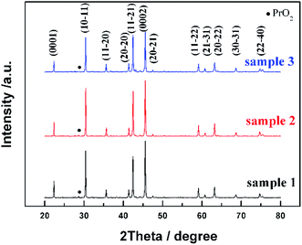
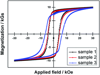
X-ray diffraction patterns of the three samples are shown in Fig. 1. All diffraction peaks could be indexed to the standard patterns of PrCo5 (JCPDS 17-0906) and PrO2 (JCPDS 24-1006). The patterns for the samples indicate the most intense peaks correspond to the PrCo5 pattern with a small amount of PrO2 phase (volume fractions less than 1.5%). The indexed (0001) and (0002) planes correspond to the c-axis in the PrCo5 crystal, and the indexed (11−20) and (22−40) planes are perpendicular to the c-axis. For each sample, the strongest diffraction peak is at (0002) position, indicating the strong anisotropic distribution of habit planes by referring to the c-axis. Meantime, the (11−21) peak represents the isotropic distribution of habit planes. Therefore, we use the intensity ratio of (0002) peak and (11−21) peak to represent the orientation bias of habit planes along the c-axis. The calculated results are given in Table 1. These results imply that the occurring frequencies of crystallographic planes and the corresponding crystal morphologies vary at different locations in the bulk magnet.Magnetic hysteresis loops of the three samples are presented in Fig. 2, and the measurement results of magnetic properties are also listed in Table 1. For all samples, the moderate coercivities might due to the fine grains,12 and the high remanence indicates that c-axis texture forms throughout the whole sample via hot deformation, leading to strong magnetic anisotropy in the magnet. Nevertheless, from the center to the edge location, the remanence decreases while the coercivity increases, which illustrates that the magnetic performances are heterogeneous at different locations in the bulk magnet.
The inverse pole figure (IPF) maps of the three samples are presented in Fig. 3, in which the crystallographic orientation of PrCo5 grain can be determined according to the orientation legend for hexagonal symmetries. The black regions (with a volume fraction lower than 1.5%) correspond to the phases that cannot be identified (we merely recorded the EBSD data points correspond to the PrCo5 phase, and considering the results in Fig. 1, the black regions might correspond to the PrO2 phase). Fig. 3 shows that the average grain size is not the same in the three samples: sample 1 has the maximum (about 1.610 μm), sample 2 has the intermediate (about 1.315 μm), and sample 3 has the minimum (about 1.208 μm). Note that a single grain in an EBSD map might consists of large amount of slightly misoriented (within the tolerance angle of 5° in this work) aligned crystals. These results also indicate that the morphologies of grains differ at different locations in the bulk magnet; meanwhile, the volume fractions of PrCo5 crystals with the 〈0001〉 crystal direction aligned with ND as a function of misalignment of the samples are quite similar; therefore, it might be speculated that grains at the center locations are with higher deformation rate than those at the edge locations.
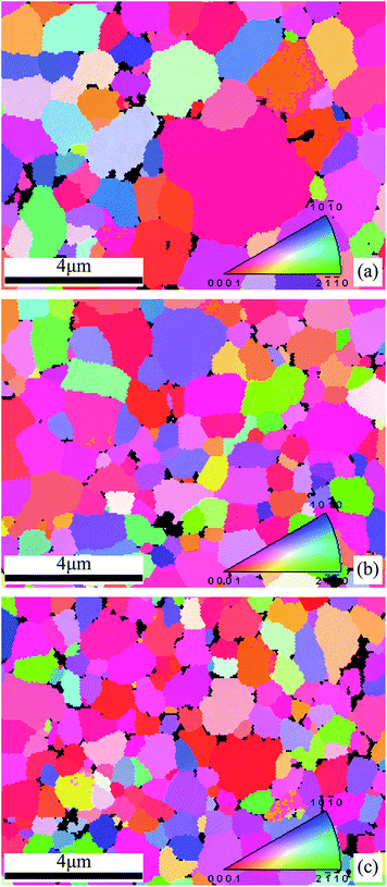 | ||
| Fig. 3 Inverse pole figure (IPF) maps of the samples: (a) sample 1, (b) sample 2, (c) sample 3; with orientation legend for hexagonal symmetries. | ||
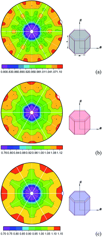
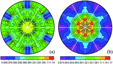
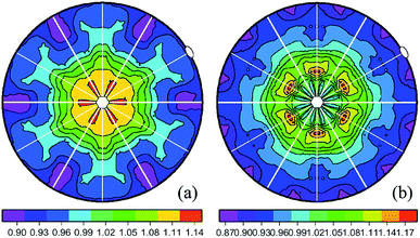
For the three samples, the misorientation averaged GBPDs are plotted into the crystal reference frame in Fig. 4. Values greater than one MRD indicate that the total area associated with a specific habit plane is larger than the area that would be expected in a random distribution, and values less than one MRD are associated with specific habit planes whose total areas are less than the area that would be expected in a random distribution.7 The most frequently occurring habit planes are {4−1−30} in sample 1 (see black oval in Fig. 4a), {10−10} in sample 2 (see red oval in Fig. 4b), and {2−1−10} in sample 3 (see blue oval in Fig. 4c), with relative areas of 10%, 12% and 15% higher than that in the random distribution, respectively (see MRD bars in Fig. 4). In contrast, the {0001} plane (see hexagons in Fig. 4) are found as the least frequently occurring habit plane in the three samples, with relative areas of 20%, 24% and 30% less than that in the random distribution, respectively (see MRD bars in Fig. 4). The GBPD results indicate that the orientation texture of crystallographic habit planes in the PrCo5 bulk magnet is also heterogeneous at different locations.
One recent significant development of the FPA method is to estimate the average three-dimensional crystal shape by combining the geometric information with the crystal orientation data.13–15 In the current work, we mainly concern the orientation textures by referring to the magnetically easy direction (the c-axis) and hard direction (axes perpendicular to the c-axis).16 Therefore, we roughly estimate the average three-dimensional crystal shape by merely comparing the dimensionless C MRD values (that the hexagon indexes have in Fig. 4 and represent the c-axis in PrCo5) with A MRD values (that the oval indexes have in Fig. 4 and represent the a-axis in PrCo5) despite the different crystallographic habit planes (whose normals are perpendicular to the c-axis) that have been observed (see colorized ovals in Fig. 4). The detailed approach is to draw an idealized hexagonal polygon with a basal side length m and a prismatic height n according to:
| Properties | Sample 1 | Sample 2 | Sample 3 |
|---|---|---|---|
| C (total basal area) | 0.800 | 0.760 | 0.700 |
| A (total prismatic area) | 1.100 | 1.120 | 1.150 |
| C/A | 0.727 | 0.633 | 0.609 |
| m | 0.392 | 0.382 | 0.367 |
| n | 0.467 | 0.488 | 0.522 |
| Volume of the polygon | 0.186 | 0.185 | 0.183 |
4. Discussion
4.1 The correlation between the local orientation texture of habit planes and local magnetic performance
The current work concerns the relevance between local orientation anisotropy of habit planes and local magnetic performance of the PrCo5 bulk magnet, and is described by the local average shape of magnetic crystals. It is necessary that the step size of the EBSD measurement (60 nm in the current work) is less than 1/20 of the average grain size (1.610 μm, 1.315 μm and 1.208 μm for the three samples in the current work), ensuring that each line segment is associated with the reliable crystal orientation parameters (taken sample 3 as an example, each grain edge is defined by more than 20 pixels, and a 0.06 micron step in the middle of a 1.208 micron line segment would maximally induce a deviation angle of 2.8°, which is below the tolerance angle of 5° to determine the grain orientations in this work).As to the local orientation anisotropy of habit planes, the X-ray diffraction results (see Fig. 1) illustrate that the (0002) planes have the strongest peaks in the three samples and therefore might imply a strong orientation texture of habit planes along the c-axis. By comparing the diffraction peak intensities at (0002) and (11−21) positions (see Table 1), it can be estimated that the orientation texture of habit planes along the c-axis differs at different location in the bulk magnet, with the crystals at the center location showing strongest orientation bias. Note that in X-ray diffraction patterns, different crystallographic facets present different diffraction intensities, and possible reasons may include the disparity of both diffraction capability between different facets and the amount of particular facets that parallel to the test surface; that is to say, the X-ray diffraction can only partially represent the orientation bias of habit planes.
As to the local magnetic performances, the major magnetic properties are also found spatially inhomogeneous at different radial locations (see Fig. 2 and Table 1). For the hot deformed PrCo5 bulk magnet, from the center to the edge location, the remanence decreases from 8.52 kGs to 7.52 kGs, illustrating that the deformation texture is inhomogeneously developed at different locations during the hot deformation process.17 It can be intuitively observed (from Fig. 3) that grains (or, crystal clusters) at the center locations are with higher deformation rate than those at the sub-center and edge locations considering the similar misalignment situations at different locations, however, the development of the orientation texture of crystallographic habit planes during hot deformation can not be quantitatively described.
Measurements of both local orientation anisotropy of habit planes and local magnetic performance indicate that it is significantly necessary to measure the orientation textures of crystallographic habit planes, and the statistical computational results plotted in the crystal reference frame are presented in Fig. 4, which overall reveals that the orientation biases of habit planes are heterogeneous at different locations. To emphasize, in Fig. 4, MRD values merely represent the orientation texture intensities of habit planes, and the orientation bias of habit planes is directly result from the hot deformation (with height reduction as a common proxy, see Section 4.2 for more detail). In the current work, both the {0001} planes (see hexagons in Fig. 4) and habit planes that are perpendicular to the {0001} planes (see ovals in Fig. 4) occur with different frequencies at different locations (see Table 1). By virtue of the idealized polygons, it is highlighted that the local orientation texture of habit planes could substantially describe the local average three-dimensional shape of magnetic crystals. In more detail, an idealized polygon represents the average three-dimensional shape of (a large amount of) crystals that supplied the line segments to calculate the misorientation averaged GBPD.14,15 By using the idealized polygons, one can observe that orientation bias of crystallographic habit planes (by referring to the easy and hard directions) are differently developed at different locations (see A and C values in Table 2). The crystalline characteristics of PrCo5 can be described as a hexagonal space group of P6/mmm type,18,19 therefore, the geometric parameters of the idealized polygons can also be used as the proxy for the weight of orientation texture along the c-axis. A larger C/A ratio in an idealized polygon could represent a higher magnetic anisotropy with higher weight along the c-axis, which could in turn lead to a higher remanence in this magnetically easy direction. Actually, the computational results in Table 2 are fully consistent with the measured results in Fig. 2 and Table 1. Note that the idealized polygons are abstracted from the two-dimensional GBPD results and represent the orientation bias of habit planes in the final bulk magnet, therefore, the orientation texture of habit planes (with C/A ratio as the proxy) could manifest a more or less monotonic function with the remanence. Besides, by using the idealized polygons, one can roughly estimate the grain size at different locations. In the current work, with the tolerance angle of 5°, what is presented as the increasing size of the EBSD “grains” towards the middle of the sample (see Fig. 3) is likely to reflect not only the increasing probability of the slightly misoriented adjacent crystals appearing as single EBSD “grain”, but also the real growth of the crystals. In this meaning, the real grain sizes in Fig. 3 are totally consistent with the volume values of the polygons in Table 2.
There are several methods to measure the axial [0001] texture, for example, the measurement of {0001} pole figure (which measure the orientation texture of grains), and the comparison between the X-ray diffraction intensity at (000l) position and reference position (see Fig. 1 and Table 1 in this work). In current work, habit plane orientation texture with the idealized hexagonal polygon as the expression measures the two-dimensional (means the misorientation parameters are averaged) orientation texture of boundary planes. Via this method, the relative lengths of the c-axis and a-axis of a batch of crystals can be measured, which can help to understand the remanence of that batch of crystals at different locations on a statistical level. Therefore, the major contribution of the current work is that the local average shape of grains in the magnet could be quantitatively described, which in turn could promote the understanding about the relevance between the local orientation texture of habit planes and the local magnetic performance. Recent studies have indicated that the GBPD is determined by the boundary energy,20 and the boundary energy is closely correlated to the performances of polycrystalline materials.21 One of the major development tendencies of the permanent magnets is miniaturization, which brings forward the necessity to control the local magnetic anisotropy in a much smaller dimension (see our recent developments about possible approaches in Section 4.2). In this sense, the current work presents a new approach to quantitatively describe the relationship between the orientation texture of habit planes and the corresponding magnetic performance.
4.2 Possible routines to control the local orientation texture of habit planes
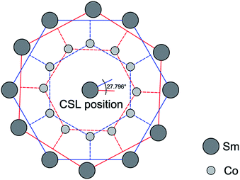
As mentioned above, controlling the local magnetic anisotropy in a much smaller dimension is significant to precisely obtaining the local magnetic performances. In this section, the authors would like to succinctly introduce our preliminary attempts about the possible routines to control the local magnetic anisotropy. No new experimental work is included in this section, the new computational as well as the analytic work could be taken as the beneficial extension of our previous report.22,23In our previous work,22 the 27.796°/[0001] misorientation relationship (or in a coincidence site lattice (CSL) nomination, the Σ13a boundary) has been found to be remarkably preferred in SmCo5 magnet (which has quite similar lattice structure with PrCo5), and (0001) planes are more populous in the more highly deformed samples than in the less deformed samples. Our previous work23 has also revealed the feasibility to accurately filter the boundaries according to the misorientation relationship across the boundaries. These developments spontaneously present the potential pathway to control the local magnetic anisotropy via locally obtaining boundaries with particular misorientation relationships.
Compared with crystal interiors, boundaries could be regarded as structural defects with different microscopic structures. As to the CSL boundaries (refer to Σ13a boundary in the current work), the higher reciprocal density of coinciding sites (see scheme for Σ13a boundary in Fig. 5) and more symmetrical configuration of dense planes (see the characterization result of Rodrigues misorientation in Fig. 6 where the crystal axes are chosen as reference or in other words, the axis mesotexture can be measured) might result in special pinning effects at spatial position of CSL boundaries; therefore, the misorientation relationship across the CSL boundaries might be significant to the movement of magnetic moments,24 or domains, and in turn could determine the local magnetic performances. Fig. 7 presents an example that the GBPD various by referring to whether the misorientation is close to the 27.796°/[0001] relationship. Fig. 8 presents an example that the GBPD varies by referring to the degree of hot deformation. These examples demonstrate that the local magnetic anisotropy might be controlled by virtue of local misorientation tuning.
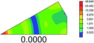 | ||
| Fig. 6 The misorientation distribution of boundary planes in Rodrigues–Frank space for an SmCo5 bulk magnet. The strong preference of [0001] axes (at the vertex position) can be observed. | ||
5. Conclusions
Both the orientation texture of crystallographic habit planes and the magnetic performances are heterogeneous at different locations in a hot deformed PrCo5 bulk permanent magnet. By virtue of the misorientation averaged FPA method, the local average shape of magnetic crystals has been quantitatively described. This has helped to understand the relevance between the local orientation texture of habit planes and the local magnetic performance. The work provides an approach to explain the relevance between the orientation anisotropy of habit planes and the magnetic anisotropy of permanent magnets.Acknowledgements
Dongtao Zhang and Xiaokun Yuan contributed equally to this work. Ming Yue acknowledges support from the State Key Program of Natural Science Foundation of China 51331003. Xiaokun Yuan acknowledges supports from the National Natural Science Foundation of China 51471007 and the State Key Lab of Advanced Metals and Materials 2013-Z01. Dongtao Zhang acknowledges support from the Beijing Natural Science Foundation 2152006. Xiaokun Yuan is truly grateful to Prof. Gregory S. Rohrer (Carnegie Mellon University, USA), Prof. Zaven Altounian (McGill University, Canada) and Prof. Yuan Ji (Beijing University of Technology, China) for giving important insight, and appreciates Dr Zhixue Qu for sharing fruitful discussion, with Dr Yuntao Lei for providing kind help to this work, and with Dr Hongmei Xu for giving linguistic advice.Notes and references
- G. C. Hadjipanayis, J. Magn. Magn. Mater., 1999, 200, 373 CrossRef CAS.
- Z. M. Chen, B. Meng and G. C. Hadjipanayis, Appl. Phys. Lett., 1999, 75, 3165 CrossRef CAS PubMed.
- M. Yue, J. H. Zuo, W. Q. Liu, W. C. Lv, D. T. Zhang, J. X. Zhang, Z. H. Guo and W. Li, J. Appl. Phys., 2011, 109, 07A711 CrossRef PubMed.
- W. Z. Yin, R. J. Chen and X. Tang, IEEE Trans. Magn., 2014, 50, 2100704 Search PubMed.
- D. M. Saylor, B. S. Dasher, B. L. Adams and G. S. Rohrer, Metall. Mater. Trans. A, 2004, 35, 1981 CrossRef.
- D. M. Saylor, B. S. El Dasher, A. D. Rollett and G. S. Rohrer, Acta Mater., 2004, 52, 3649 CrossRef CAS PubMed.
- G. S. Rohrer, D. M. Saylor, B. S. El-Dasher, B. L. Adams, A. D. Rollett and P. Wynblatt, Z. Metallkd., 2004, 95, 197 CrossRef CAS.
- J. Li, S. J. Dillon and G. S. Rohrer, Acta Mater., 2009, 57, 304 Search PubMed.
- G. S. Rohrer, J. Mater. Sci., 2011, 46, 5881 CrossRef CAS.
- G. S. Rohrer, J. Am. Ceram. Soc., 2011, 94, 633 CrossRef CAS PubMed.
- H. Beladi, G. S. Rohrer, A. D. Rollett, V. Tari and P. D. Hodgson, Acta Mater., 2014, 63, 86 CrossRef CAS PubMed.
- W. Q. Liu, J. H. Zuo, M. Yue, D. T. Zhang and J. X. Zhang, J. Appl. Phys., 2011, 109, 07A731 Search PubMed.
- A. D. Rollett, Stereology applied to GBPD (L17), in Texture, Microstructure and Anisotropy, 27–750, Carnegie Mellon MRSEC, 2011 Search PubMed.
- C. S. Kim, T. R. Massa and G. S. Rohrer, J. Am. Ceram. Soc., 2008, 91, 996 CrossRef CAS PubMed.
- X. K. Yuan, G. S. Rohrer, X. Y. Song, H. Chien and J. Li, Int. J. Refract. Met. Hard Mater., 2014, 44, 7 CrossRef CAS PubMed.
- K. Guth, T. G. Woodcock, J. Thielsch, L. Schultz and O. Gutfleisch, J. Appl. Phys., 2011, 109, 07A764 CrossRef PubMed.
- Z. D. Zhang, Acta Phys. Sin., 2015, 64, 067503 Search PubMed.
- G. S. Rohrer, Structure and bonding in crystalline materials, Cambridge University Press, Cambridge, 2004 Search PubMed.
- M. de Graef and M. E. McHenry, Structure of materials: an introduction to crystallography diffraction and symmetry, Cambridge University Press, Cambridge, 2007 Search PubMed.
- H. J. Ryu, D. B. Fortner, G. S. Rohrer and M. R. Bockstaller, Phys. Rev. Lett., 2012, 108, 107801 CrossRef.
- C. L. Wang, Z. X. Qu, Y. He, D. Luan and W. Pan, Phys. Rev. Lett., 2008, 101, 085901 CrossRef.
- X. K. Yuan, M. Yue, D. T. Zhang, T. N. Jin, Z. R. Zhang, J. H. Zuo, J. X. Zhang, J. Zhu and X. X. Gao, CrystEngComm, 2014, 16, 1669 RSC.
- X. K. Yuan, D. T. Zhang, S. L. Zhou, M. Yue, J. X. Zhang, J. Zhu, Q. Ma and Z. Wang, CrystEngComm, 2015, 17, 4210 RSC.
- S. Ii, K. Hirayama, K. Matsunaga, H. Fujii and S. Tsurekawa, Scr. Mater., 2013, 68, 253 CrossRef CAS PubMed.
| This journal is © The Royal Society of Chemistry 2015 |

