DOI:
10.1039/C5RA11762C
(Paper)
RSC Adv., 2015,
5, 68929-68938
Organic dyes for the sensitization of nanostructured ZnO photoanodes: effect of the anchoring functions†
Received
18th June 2015
, Accepted 3rd August 2015
First published on 4th August 2015
Abstract
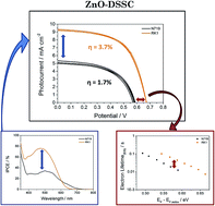
Among all n-type metal oxide semiconductors that can be used in solar cells as photoanode, ZnO is one of the most appealing alternatives to the ubiquitous TiO2. This material offers some potentially favourable characteristics with respect to TiO2, such as higher electron mobility in the bulk and a rich variety of nanostructures. However, ZnO has certain drawbacks as photoanode material, for example, a poor chemical stability and a slower charge separation process at the ZnO interface that reduces the electron injection rate. Therefore, in the case of dye-sensitized solar cells, the search of new dyes with a higher light harvesting efficiency and specifically designed to bind to ZnO can be considered as a possible strategy to improve performance in systems characterized by a low electron injection rate. In this work the optical, electrochemical and photovoltaic properties of a family of purely organic sensitizers with various anchoring groups have been investigated and compared with the most commonly used ruthenium dye N719. In particular, we have shown that the structurally simple organic dye coded RK1 is an excellent sensitizer for ZnO photoanodes. Thanks to this molecule, the energy conversion efficiency under standard conditions (1 sun AM 1.5 illumination) employing ZnO-based photoanodes reached 3.7%, which is more than two times higher than obtained with the N719 dye studied under the same conditions.
Introduction
Among all components of a Dye-Sensitized Solar Cell (DSSC),1,2 the function of light absorption and charge separation by means of electron injection in the semiconductor is carried out by the sensitizer dye molecules. However, not only the generation of an electric current depends on the properties of the dye, but also the electron recombination with the oxidized species present in the electrolyte, which determines the photovoltage of solar devices.3 Therefore, bearing in mind the importance of dyes in the global performance of DSSC, the study and development of new sensitizers have received much interest. Among them one can cite the ruthenium-containing dyes such as polypyridyl complexes, the metallated porphyrins and the fully organic dyes. Recently, a clear breakthrough in the field has been the use of lead perovskites in solar cells.4–6
Since the origins of DSSCs, the most employed dyes are ones containing ruthenium complexes, which have demonstrated high efficiencies. These dye molecules are characterized by the occurrence of a Metal-to-Ligand Charge Transfer (MLCT) feature with a wide absorption spectrum and a moderate absorption coefficient.7 The latter characteristic has negative influence on the performance of these dyes in solar cells with ionic liquids or solid hole conductors as electrolytes, where the mass transfer limitation and the rapid recombination requires very thin films as photoanodes. As an additional drawback, the dyes containing ruthenium, an exceedingly rare metal, are associated with high fabrication costs. Nevertheless, the ruthenium dyes show a long excited-state lifetime, a good electrochemical stability under illumination and appropriate energy levels (LUMO and HOMO) for an efficient electron injection and for rapid dye regeneration when TiO2 nanostructures are used as photoanodes.
In the search and development of new sensitizers, fully organic dyes, which are characterized by a high absorption coefficient,8 have extensively been studied. Up to date, numerous papers demonstrate efficiencies of DSSCs comparable to the ones where ruthenium dyes are used. For instance, efficiencies of 10.1% (C219)9 and 12.3% (co-sensitization by YD2-o-C8 porphyrin dye and other organic Y123 dye)10 have been achieved under simulated 1 sun AM 1.5 global sunlight. The advantage of these dyes, among other properties, is not only their high absorption coefficients, but also the low production costs and the possibility to modify the routes of synthesis and to change the absorption spectrum by the incorporation of new groups.11,12
Among organic dyes, the family of donor–π–acceptor (D–π–A) dyes has received increased attention due to easier modification of the chemical structure.9,13–16 These dyes result from the combination of two units linked covalently through a spacer (π-bridge). One of them is an electron donor group, whose aim is to increase light absorption and to facilitate regeneration of the dye, whereas the other unit is an electron acceptor group, which favours electron injection in the semiconductor after the intramolecular charge transfer from electron donor group. Thanks to this molecular design it is possible to create new dyes modifying the chemical structure of each unit.
In this work, we study the photovoltaic performances of nanostructured ZnO photoanodes sensitized with different organic D–π–A dyes that we compare to a reference compound i.e. the ruthenium complex coded N719. All the organic dyes employed in this study (Fig. 1) are derived from the same π-conjugated system inspired by the dye (RK1), for which an efficiency of over 10% has been demonstrated on TiO2.17 Owing to the good performances of this dye, our objective in this work was to assess its potential with ZnO electrodes and to adapt its chemical structure in order to investigate the interfacial processes that govern the generation of current in this type of solar cells. Indeed despite of the fact that many organic dyes have been published in the recent years,14–16 the literature dealing with the tuning of their chemical structure specifically for the sensitization of ZnO electrode is very scarce. In particular, the main differences between these organic dyes is related to the substitution of the triphenyl amine with alkoxy groups and/or the number and nature of the anchoring groups, standing out the MG100 dye by the presence of a phosphoric acid group specifically adapted to bind to ZnO.
 |
| Fig. 1 Structure of the organic dyes employed in this work. | |
At this point it is important to mention the limitations of the application of ZnO electrodes as photoanodes in DSSC. In previous works it has been discussed that ZnO-based solar cells show worse performance with respect to TiO2-based solar cells as a consequence of the lower electron injection rate, slower dye regeneration and/or the presence of an intermediate state of the dye with strong back recombination.18,19 In addition, ZnO electrodes show a high instability in the presence of ruthenium dyes, such as N719 or other acidic dyes. A partial dissolution of the semiconductor and the formation of dye-ZnO aggregates have been evidenced after the immersion in acidic dye solution.20–24 Nevertheless, the record efficiency for ZnO-based solar cells (7.5%) has been achieved using hierarchically assembled ZnO nanocrystallites deposited on a ZnO buffer layer and N719 as the sensitizer.25 However, efficiencies higher than 5% were achieved using ZnO nanowires sensitized by SK1 (D–π–A dye) in combination with cobalt complex as redox shuttle.26 In this work, DSSCs were fabricated using ZnO nanoparticles as photoanodes sensitized with the different organic dyes. Among them the sensitizer coded RK1 has shown the highest performances and a twice as high power conversion efficiency in comparison to the DSSCs containing ruthenium dye.
Results and discussion
Synthesis of the dyes
In this work we have used as reference materials two dyes from the RK series that have demonstrated power conversion efficiencies of over 10% for mesoporous TiO2 electrodes in DSSC configuration.27 In addition, two new dyes were synthesized differing by the nature and the number of anchoring functions.
These are MG41, that contains a double anchoring cyanoacrylic acid group and MG100, with a cyanovinylphosphonic group (Scheme 1). The dyes were synthesized in three steps through classical cross-coupling reactions under Stille or Suzuki conditions. The introduction of the anchoring groups was performed using Knoevenagel condensations. For MG100, the cleavage of the phosphonate group was achieved using iodo-trimethylsilane following standard procedure.28
 |
| Scheme 1 Synthesis of the dyes studied in this work. | |
Optical and electrochemical characterisations
The UV-Vis spectra of the solution of the organic dyes in dichloromethane are shown in Fig. 2A. The spectra are characterised by the presence of two absorption bands. The most intensive band located in the UV region is associated with the high-energy π–π* orbital transition. On the other hand, the band located in the visible region is associated with the intramolecular charge transfer from the electron donor to the electron acceptor group. For RK1, 6ORK1, MG41 and MG100 dyes, the latter absorption band exhibits absorption maxima at 481, 503, 492 and 492 nm, respectively, with a molar absorption coefficient of 29
800, 20
000, 11
200 and 12
300 M−1 cm−1 (Table 1). As expected, the intensity and the position of the ICT bands are dependent on the modification of the chemical structure.12 Indeed, the introduction of two electron-donating alkoxy-substituents on the TPA unit induces a bathochromic shift of the ICT band for all the dyes compared to RK1. Simultaneously, the molar extinction coefficients are decreased for these three dyes due to the additional alkyl chains that do not contribute to the absorption. In the case of MG41 and MG100, the less effective conjugation of the anchoring functions with the rest of the π-conjugated system (also demonstrated by theoretical calculations) explains their much lower molar absorption coefficients.
 |
| Fig. 2 (A) UV-Vis spectra of synthesized dyes studied in dichloromethane and (B) adsorbed onto the ZnO surface. | |
Table 1 Photophysical data: (a) measured in CH2Cl2, (b) determined from the onset of the first oxidation and reduction (c) calculated Eg = HOMO − LUMO. All potentials were obtained during cyclic voltammetric investigations in 0.2 M Bu4NPF6 in CH2Cl2. Potentials measured vs. Fc+/Fc were converted to NHE by addition of +0.69 V. Platinum electrode diameter was 1 mm, sweep rate: 200 mV s−1. (d) Calculated at B3LYP level of theory
Dye |
λabs(a) (nm) |
ε(a) (M−1 cm−1) |
HOMO(b) (V vs. NHE) |
LUMO(b) (V vs. NHE) |
Eg(c) (eV) |
HOMO(d) (V vs. NHE) |
LUMO(d) (V vs. NHE) |
Eg(d) (eV) |
RK1 |
481 |
29 800 |
0.76 |
−1.22 |
1.98 |
0.73 |
−1.28 |
1.91 |
6ORK1 |
503 |
20 000 |
0.53 |
−1.16 |
1.69 |
0.59 |
−1.23 |
1.82 |
MG41 |
492 |
11 200 |
0.52 |
−1.22 |
1.74 |
0.54 |
−1.36 |
1.90 |
MG100 |
492 |
12 300 |
0.48 |
−1.24 |
1.72 |
0.53 |
−1.35 |
1.88 |
Assuming that all photoanodes have the same surface area, a higher molar absorption coefficient should be correlated with a higher absorption signal, as shown in Fig. 2B for RK1-6ORK1- and MG41-ZnO photoanodes. Nevertheless, the MG100-ZnO photoanode shows an absorption maximum very similar to that for the RK1-ZnO photoanode (0.05 and 0.044, respectively), whereas the absorption coefficient for MG100-ZnO is almost three times smaller (Fig. 2A). Therefore, a higher concentration of dye molecules on ZnO surface may be inferred from the results in the case of MG100-ZnO.
In order to determine the position of the LUMO and HOMO levels of the organic dyes an electrochemical study was performed by means of cyclic voltammetry (Table 1). Both energy levels were determined from the oxidation and reduction onset with respect to NHE. The band gap energy was determined by the energy difference between the levels. Although the HOMO–LUMO difference does not necessarily corresponds to the energy absorption onset, it is still a good approximation for the energy difference between ground and excited state. A value of the band gap of around 1.7–2.0 eV confirms that the organic dyes have a relatively strong absorption in the visible range of wavelengths.
To compare these experimental values and to gain insight into structural properties, the electron density distribution of the frontier orbitals of the dyes was determined by density functional theory (DFT) using the B3LYP hybrid functional. The calculated HOMO–LUMO gaps are shown in Table 1, where we observe the same trend as experimentally determined, i.e. RK1 > MG41 > MG100 > 6ORK1. The HOMO and LUMO energies and spatial representations of the two new dyes are shown on Fig. 3 and compared to those of 6ORK1. The energy levels of LUMO and HOMO are well positioned with respect to the conduction band edge of the semiconductor (−0.4 V versus NHE) and redox potential of I−/I3− in the electrolyte (0.35 V versus NHE). As a consequence, efficient electron injection and dye regeneration are expected. Moreover the LUMO constitution deserves some attention. For MG41, we see clearly LUMO extension on both cyanoacrylic groups. For MG100, we see absolutely no contribution from the PO3H2 group whereas for 6ORK1, the LUMO has some extension over the COOH group. The contribution of the COOH to the LUMO is comprised between 2.21 and 4.51% (see ESI, Table S1†). This contribution can be explained by the conjugation of the C
C bond with CN and of the C
O from CO2H, whereas with the phosphonic group, no conjugation is expected.
 |
| Fig. 3 Frontier molecular orbitals of the dyes calculated at B3LYP level of theory. | |
Photovoltaic performance
As reported in the literature, due to the low chemical stability of ZnO, the concentration of the dyes in solutions and the sensitization time are key factors for an optimal dye adsorption in the case of ZnO photoanodes.20,21 In particular, due to the dissolution of ZnO by the acidic carboxylic groups of dyes, Zn2+-dye complexes are produced, which can affect the electron injection kinetics.22–24 For this reason, the sensitization time for a given dye concentration has been optimized prior to the characterization study (see ESI, Fig. S1†). No significant differences were found in the first 3 hours for RK1-DSSCs. Nevertheless, for the rest of organic dyes a clear deterioration of the fill factor and even the short-circuit photocurrent was observed. The deterioration of these parameters could be attributed to a degradation of the electrodes during the staining step, because it is well-known that ZnO electrodes can be etched under acidic conditions.22 To verify this hypothesis the pH of ethanol solution containing 0.2 mM of each dye was measured. We found that the more acidic dyes are MG41 and MG100, the less acidic one being RK1. Therefore a quicker degradation of the ZnO electrodes as a consequence of the dissolution of ZnO and formation of Zn2+-dye aggregates during the dye sensitization23,24 is expected with MG100, MG41 and 6ORK1 that are more corrosive compared to RK1. Thus, for the preparation of the sensitized photoanodes later used in DSSCs, the sensitization time was restricted to only one hour, while a shorter period usually leads to non-sufficient adsorption of dyes on the mesoporous ZnO electrodes.24
In order to analyze the photovoltaic properties of the different dyes, the overall light conversion efficiency of ZnO-DSSC has been determined by means of I–V curve measurements. Fig. 4A shows current–voltage characteristics of DSSCs employing a thin film (≈4 μm) of ZnO as photoanode sensitized with the different dyes. Bearing in mind the insensitivity of ZnO under the presence of potential determining additives reported recently,19 the employed electrolyte in this work consists of only a redox pair (0.05 M I2 + 0.5 M BMII) in acetonitrile as solvent electrolyte. The ruthenium dye N719 has been used as sensitizer for the reference cell.
 |
| Fig. 4 (A) Current–voltage curves of the best performing device under 1 sun AM 1.5 illumination and (B) corresponding incident photon-to-electron conversion efficiency spectra as a function of monochromatic wavelength for the dyes studied. | |
As shown in Table 2, the highest efficiency (3.3%) was found for RK1-DSSC. This efficiency is achieved by the combination of the highest photocurrent (8.2 mA cm−2) and photovoltage (675 mV). In addition, a rather good fill factor is obtained for RK1-DSSC, especially when it is compared to the other organic dyes. As a consequence of the low fill factor of 6ORK1-DSSC, this dye shows a similar efficiency to N719-DSSC (1.7% and 1.6%, respectively) in spite of showing a higher photocurrent and photovoltage. On the other hand, MG41-DSSC and MG100-DSSC show a comparable photocurrent to N719-DSSC. Nevertheless, due to their low fill factor, these DSSCs show the lowest efficiencies (1%). Previous studies29–31 have shown that higher rates of electron recombination lead to poor fill factors, which suggests that 6ORK1-, MG41- and MG100-DSSC suffer a faster recombination. In addition, the fill factor may be lowered by the presence of dye aggregates in the pores impeding the transport of the redox couple, which is less of a factor for the RK-1 dye.
Table 2 Photovoltaics parameters of the best performing device for each dye for a non-optimized architecture obtained under simulated AM 1.5 illumination
Dye |
Jsc (mA cm−2) |
Voc (mV) |
Fill factor (%) |
Efficiency (%) |
N719 |
4.9 |
610 |
52 |
1.6 |
RK1 |
8.2 |
675 |
60 |
3.3 |
6ORK1 |
6.9 |
630 |
39 |
1.7 |
MG41 |
4.4 |
555 |
41 |
1 |
MG100 |
5.6 |
620 |
30 |
1 |
The short circuit photocurrent can be determined via
|
 | (1) |
where IPCE is the incident photon-to-electron conversion efficiency, which is defined as the number of electrons generated in the solar devices with respect to the number of incident photons for a given wavelength, hence,
|
 | (2) |
where
Jsc(
λ) is the short-circuit photocurrent at a given wavelength (mA cm
−2),
λ is the wavelength (nm) of the incident light,
Plight is the power of incident light (W m
−2) and 1240 is a conversion factor. In particular, as shown in
Fig. 4 the difference of short-circuit photocurrents is fully consistent with the differences of the IPCEs.
RK1-DSSC, along with showing the higher photocurrent, shows an IPCE closer to 80% at the absorption maximum, whereas in the case of
N719-DSSC an IPCE lower than 40% has been recorded. The IPCE depends on the efficiency of three different processes that determine the electrical conversion in a DSSC,
|
IPCE(λ) = ηlh(λ)ηg(λ)ηcol(λ)
| (3) |
where
ηlh is the light harvesting efficiency,
ηg is the generation efficiency of electrons under sunlight irradiation (including dye regeneration), and
ηcol is the charge collection efficiency from the device to the external circuit. Bearing in mind
Fig. 2B,
MG100-DSSC shows the highest light harvesting efficiency. Nevertheless,
RK1-DSSC, whose light harvesting efficiency is approximately similar to
MG100-DSSC, shows the maximum IPCE. If good electron collection efficiency is assumed at short-circuit conditions,
8,32,33 two possible explanations could be suggested. First,
MG100 has the highest light harvesting efficiency but leads to a poor electron injection in the ZnO semiconductor or second, the dissolution of Zn
2+ during the dye sensitization is more intense in the case of
MG100. Taking into account the second assumption, a higher concentration of Zn
2+-dye complexes is accumulated in the pores of semiconductor. If it is assumed that the electron injection is only carried out by dye molecules directly attached to the ZnO surface, these complexes can only contribute to the light harvesting efficiency but not to the electron injection.
34 Both assumptions are probably related to the chemical nature of the phosphonic acid group that links this dye to the oxide, which may hinder the electronic overlap between the excited state of the dye and acceptor states in the oxide.
Optimization of architecture of dye-sensitized solar cell
To optimize the energy conversion efficiency achieved in the previous section using RK1 dye as sensitizer, different thicknesses of ZnO films have been tested. It should be kept in mind that the thickness of the mesoporous semiconductor films plays an important role in the performance of these solar devices because it determines the different photovoltaic parameters.35,36 The thickness of the photoanode is very important to the adsorption of the dye and the electron recombination with the reduced species present in the electrolyte, which determine the Jsc and Voc respectively. These two factors are intimately related to the surface area of semiconductor. It is expected that increased thickness will increase the photocurrent, due to the larger surface area available for the attachment of dye molecules. However, a decrease of the photovoltage is also expected as a consequence of the increase of electron recombination due to the increase of the semiconductor/electrolyte interfacial area. Fig. S2 (see ESI†) confirms this expectation. Thus, bearing in mind the high absorption coefficient of RK1 dye (Fig. 2A), the thin film of 4 μm shows only a difference of 1.5 mA cm−2 with respect to the thicker film of 8 μm. Therefore, an increase of the thickness contributes only to small increase of the photocurrent and an important efficiency loss due to the electron recombination. In contrast to the previous section, to guarantee the penetration of dye solution through the structure of photoanodes and to make sure that the entire surface in the thicker films is covered, a sensitization time of 90 min was used. Fig. 5 shows current–voltage characteristics of the optimal architecture for DSSCs employing an 8 μm thick ZnO film as photoanode sensitized with the organic dye RK1 and the ruthenium dye N719. In particular, RK1-DSSCs show a two-fold higher efficiency than for N719-DSSCs (3.7% and 1.7%, respectively). It should be noted that when TiO2 is employed as photoanode, very similar solar cell performances have been achieved for both dyes (see ESI, Fig. S3†). In Fig. 5, RK1-DSSCs show a short-circuit photocurrent of 9.3 mA cm−2 whereas in the case of N719-DSSCs values of 5.2 mA cm−2 has been found. The effect of surface area is intimately related with the average particle size, which is relatively large for the ZnO particles used in this work (40–100 nm), resulting in a BET surface area of 4 m2 g−1. This surface area is significantly lower than for TiO2 DSSCs, where the BET surface area is generally about 80 m2 g−1. Hence, the much higher absorption coefficient of the organic dyes used here is essential for the performance of the solar cells, also because the film thickness is similar as generally applied in TiO2 DSSCs. On the other hand, it was observed from desorption measurements that the RK1 dye adsorbs at ZnO at a higher coverage than the N719 dye by a factor of 1.7 (see ESI, Fig. S4†), which also directly benefits the efficiency of the RK1-sensitized ZnO DSSCs. These observations also explain why the difference in efficiency for TiO2 DSSCs with the RK1 and N719 dyes is much less pronounced, as the surface area is much larger and does not limit cell performance.
 |
| Fig. 5 Current–voltage curves under 1 sun AM 1.5 illumination for RK1 and N719 using a 8 μm ZnO film as photoanode. | |
This difference is consistent with the IPCE showed in Fig. 4B where values approximately two times higher were reported. However, the open-circuit photovoltage is also greatly increased when RK1 (675 mV) is used as sensitizer with respect to N719 dye (585 mV). To cast light on this remarkable effect, an electrochemical impedance spectroscopy (EIS) study has been performed.37,38 By means of EIS the two factors that determine the electron lifetime (τn) via eqn (4), and then the open-circuit photovoltage, are analyzed: (1) the position of the conduction band edge by means of the chemical capacitance, Cμ, and (2) the electron recombination resistance, Rrec.
In Fig. 6, the electron recombination resistance, chemical capacitance and the electron lifetime extracted from the EIS spectra at different potential (EF − EF-redox) are reported.
 |
| Fig. 6 (A) Electron recombination resistance, (B) chemical capacitance and (C) electron lifetime data as extracted from EIS measurements in RK1-DSSC and N719-DSSC based on ZnO. | |
Fig. 6A shows a higher electron recombination resistance for RK1-DSSC than for N719-DSSC at a given value of the Fermi level. On the other hand, the chemical capacitance data (Fig. 6B) evidences a clear difference between RK1-DSSC and N719-DSSC. Similar results were found for TiO2-DSSC (see ESI, Fig. S5†). It means that the adsorption of these dyes on the semiconductor surface produces a shift of position of the conduction band edge with respect to Eredox of the electrolyte. In particular, a negative band-shift in the semiconductor oxide band edge has been found for RK1-DSSC with respect to N719-DSSC. Therefore, the energy difference between the conduction band edge and Eredox of electrolyte, which is the other factor that determines the open-circuit photovoltage, is higher for RK1-DSSCs. The electron lifetime extracted via eqn (4), as shown in Fig. 6C, is larger for RK1-DSSC compared to N719-DSSC. Consequently, RK1-DSSC shows a higher open-circuit photovoltage. These results are supported by the electron lifetimes extracted from OCVD measurements (ESI, Fig. S6†).39,40
Nevertheless, to determine the origin of the longer electron lifetime, it is necessary to distinguish between the thermodynamic effect (chemical capacitance) and kinetic effect (electron recombination resistance). Hence, it is necessary to separate out the thermodynamic effects from the electron recombination rate and compare the electron recombination resistances at the same value of the total electron density stored in the semiconductor oxide. In this work this correction has been applied by looking at the shift of the capacitance lines detected in the EIS measurements. Shifting the potential to a value at which all capacitance lines overlap, one makes sure that the electron recombination resistance is plotted at the same value of the total electron density (EF(shift) − EF-redox). Once the band-shift according to chemical capacitance data is corrected, a slightly lower electron recombination resistance was estimated for RK1-DSSC in comparison to N719-DSSC (ESI, Fig. S7†). Therefore, bearing in mind that the kinetics of electron recombination at the same value of electron density are very similar for both dyes, the band-shift of the semiconductor oxide is the main factor responsible for the different open-circuit photovoltage in both DSSCs.
Conclusions
Since the optimization of electrolyte composition by the addition of potential-determining additives does not represent a way to improve the efficiency of ZnO-DSSC, the search for new dyes with a higher absorption coefficient can be considered as an alternative strategy. In this work, the photovoltaic performances of different donor–π–acceptor organic dyes have been studied and compared with the most common ruthenium dye N719. The organic dyes are derivatives of RK1, which is a promising organic dye for DSSC applications. The main structural differences of the dye molecules obtained reside in the substitution of the triphenylamine unit and the number and nature of anchoring groups. The difference in their photovoltaic performances has been attributed to their different light harvesting efficiencies. In relation to the interaction between the dyes and ZnO surface, the use of –PO3H2 moiety as anchoring group appears to be connected with a more intense edging of the ZnO semiconductor surface and/or a poorer electron injection rate as compared to the –COOH groups.
After the optimization of the architecture of DSSCs, using the RK1 organic dye as sensitizer an overall light conversion efficiency of 3.7% has been achieved. In spite of showing similar electron recombination kinetics to N719 dye, due to the higher absorption coefficient of RK1 dye and the induced negative band-shift of the conduction band edge of the ZnO semiconductor, a higher photocurrent and photovoltage is demonstrated. In particular, the efficiency becomes more than twice as high as for the N719 dye studied under the same conditions when ZnO as photoanode is used as photoanode.
Experimental section
Synthesis of the dyes
General. Tri(o-tolyl)phosphine, tris(dibenzylideneacetone)di-palladium(0), 3,5-diformyl-phenyl-boronic acid, palladium acetate(II), diethyl cyanomethylphosphonate, trimethylsilyl iodide, 2-cyanoacetic acid and piperidine were purchased from Aldrich or TCI chemicals and used as received. Tripotassium phosphate was obtained from Acros Organics and 4,7-dibromo-2,1,3-benzothiadiazole from Orgalight. The solvents, such as anhydrous toluene, chloroform, dichloromethane, isopropanol and acetonitrile were purchased from Aldrich and used as received. Spectroscopic grade solvents from Aldrich were used for spectral measurements. Compounds 1 and 4 were synthesised according to literature.27
Synthesis of 2. Under argon, compound 1 (200 mg, 0.31 mmol, 1.0 equiv.) was dissolved in distilled THF (5.0 mL) then a 1.5 M solution of n-BuLi (250 μL, 0.37 mmol, 1.2 equiv.) was added at −78 °C. The solution was stirred for an hour at −50 °C before adding a 1.0 M n-hexane solution of Me3SnCl (406 μL, 0.41 mmol, 1.3 equiv.) at −78 °C. The solution was allowed to reach room temperature and was stirred for 2 hours. The reaction was quenched with NH4Cl and the organic phase was extracted with n-hexane, dried with Na2SO4, filtered and concentrated under vacuum. The resulting mixture was engaged without any further purification in a Stille coupling with 4,7-dibromo-2,1,3-benzothiadiazole. Under argon, the stannic compound and 4,7-dibromo-2,1,3-benzothiadiazole (86 mg, 0.31 mmol, 1.0 equiv.), Pd2dba3 (7 mg, 0.01 mmol, 4% mol) and P(o-tolyl)3 (29 mg, 0.09 mmol, 0.3 equiv.) were dissolved in anhydrous toluene (5.0 mL) and refluxed for 19 hours. The mixture was then poured into HCl (2 M). The organic phase was extracted with Et2O, washed with HCl (2 M), dried over Na2SO4 and concentrated. The residue was purified by silica gel column chromatography (pentane/CH2Cl2, 7
:
3) to obtain the desired product 2 (130 mg, yield = 49%) as a red film.1H NMR (CDCl3, 200 MHz) δ (ppm): 7.99 (s, 1H), 7.83 (d, J = 7.7 Hz, 1H), 7.67 (d, J = 7.8 Hz, 1H), 7.28 (d, J = 8.5 Hz, 2H), 7.10 (d, J = 8.5 Hz, 4H), 6.94 (d, J = 8.4 Hz, 2H), 6.85 (d, J = 8.8 Hz, 4H), 3.94 (t, J = 6.5 Hz, 4H), 2.72 (m, 2H), 1.87–1.60 (m, 6H), 1.52–1.22 (m, 22H), 0.98–0.81 (m, 9H). 13C NMR (CDCl3, 100 MHz) δ (ppm): 155.9, 154.0, 152.0, 148.6, 140.8, 140.5, 139.3, 135.4, 132.5, 131.2, 129.8, 127.5, 127.1, 125.2, 119.7, 115.5, 111.7, 68.4, 32.0, 31.8, 31.2, 29.7, 29.6, 29.5, 29.1, 25.9, 22.8, 22.8, 14.3, 14.2. Anal. calcd for C48H58N3O2BrS2: C, 67.59; H, 6.85; N, 4.93; S, 7.52. Found: C, 67.47; H, 6.99; N, 4.66; S, 7.24.
Synthesis of 3. A mixture of 2 (100 mg, 0.12 mmol, 1 equiv.), 3,5-diformylphenylboronic acid (31 mg, 0.18 mmol, 1.5 equiv.), Pd(OAc)2 (1.0 mg, 2.0 μmol, 2 mol%), K3PO4 (50 mg, 0.23 mmol, 2 equiv.), THF (2 mL), iPrOH (1 mL) and distilled water (1 mL) was stirred at 80 °C for 62 hours under air. The mixture was added to brine and extracted four times with ethyl acetate. Combined organic phases were dried over Na2SO4, filtered and concentrated under reduced pressure. The resulting mixture was purified by silica gel column chromatography (hexane/EtOAc, 8
:
2) to obtain the desired product as a red solid 3 (63 mg, yield = 66%).1H NMR (CDCl3, 200 MHz) δ (ppm): 10.2 (s, 2H), 8.80 (s, 2H), 8.43 (s, 1H), 8.09 (s, 1H), 7.94 (d, J = 7.5 Hz, 1H), 7.85 (d, J = 7.5 Hz, 1H), 7.32 (d, J = 8.7 Hz, 2H), 7.11 (d, J = 8.9 Hz, 4H), 6.96 (d, J = 8.7 Hz, 2H), 6.85 (d, J = 8.9 Hz, 4H), 3.93 (t, J = 6.5 Hz, 4H), 2.75 (m, 2H), 1.88–1.62 (m, 6H), 1.56–1.20 (m, 22H), 0.98–0.82 (m, 9H). 13C NMR (CDCl3, 100 MHz) δ (ppm): 191.0, 155.8, 153.5, 152.6, 148.5, 141.0, 140.3, 139.4, 139.2, 137.4, 135.5, 135.0, 131.3, 129.9, 129.6, 128.8, 128.6, 128.2, 127.0, 125.6, 124.5, 119.5, 115.4, 68.3, 31.9, 31.6, 31.1, 29.6, 29.4, 29.3, 29.3, 29.0, 25.8, 22.7, 22.6, 14.1, 14.1. Anal. calcd for C56H63N3O4S2: C, 74.22; H, 7.01; N, 4.64; S, 7.08. Found: C, 74.59; H, 7.16; N, 4.58; S, 7.05.
Synthesis of MG41. The compound 3 (50 mg, 0.06 mmol, 1 equiv.) and cyanoacetic acid (47 mg, 0.55 mmol, 10 equiv.) were dissolved in a mixture of acetonitrile (6 mL) and chloroform (3 mL). A few drops of piperidine were added and the reaction mixture was stirred at reflux for 15 hours. Solvents were removed under reduced pressure. The solid was taken in chloroform, washed with HCl (2 M), dried over Na2SO4, filtered and concentrated under reduced pressure. The residue was purified by silica gel column chromatography (CH2Cl2/MeOH/AcOH, 1
:
0
:
0 to 90
:
5
:
5) to obtain the desired red solid MG41 (50 mg, yield = 81%).1H NMR (THF-d8, 200 MHz) δ (ppm): 9.05 (s, 2H), 8.49 (s, 1H), 8.43 (s, 2H), 8.20 (s, 1H), 8.10 (d, J = 7.6 Hz, 1H), 8.00 (d, J = 7.6 Hz, 1H), 7.32 (d, J = 8.6 Hz, 2H), 7.07 (d, J = 9.0 Hz, 4H), 6.92 (d, J = 9.0 Hz, 2H), 6.85 (d, J = 9.0 Hz, 4H), 3.94 (t, J = 6.2 Hz, 4H), 2.76 (m, 2H), 1.85–1.67 (m, 6H), 1.59–1.21 (m, 22H), 1.00–0.81 (m, 9H). 13C NMR (THF-d8, 50 MHz) δ (ppm): 238.6, 163.3, 157.0, 154.5, 153.5, 153.4, 149.6, 141.7, 141.2, 140.0, 139.6, 136.8, 134.6, 134.2, 133.3, 132.0, 130.3, 130.0, 129.7, 129.4, 128.7, 127.8, 126.8, 126.6, 125.5, 125.5, 120.1, 116.0, 115.8, 107.2, 107.2, 68.7, 32.9, 32.6, 31.9, 30.6, 30.5, 30.4, 30.3, 30.3, 29.8, 26.7, 23.5, 14.5, 14.4. HRMS (ESI): [M − H]+ = 1039.4368 (calcd for C62H65N5O6S2: 1039.4371).
Synthesis of 5. The compound 4 (120 mg, 0.14 mmol, 1.0 equiv.) and diethyl cyanomethylphosphonate (111 μL, 0.68 mmol, 5.0 equiv.) were dissolved in a mixture of acetonitrile (10 mL) and chloroform (5 mL). A few drops of piperidine were added and the reaction mixture was stirred at reflux for 3 hours. The resulting mixture was washed with water then brine. The organic phase was dried over Na2SO4, filtered and concentrated under reduced pressure. The residue was purified by silica gel column chromatography (hexane/EtOAc, 7
:
3 to 1
:
1) to obtain the desired red film 5 (80 mg, yield = 52%).1H NMR (CDCl3, 400 MHz) δ (ppm): 8.18–8.08 (m, 4H), 8.07 (d, J = 8.4 Hz, 2H), 7.93 (d, J = 7.5 Hz, 1H), 7.80 (d, J = 7.6 Hz, 1H), 7.32 (d, J = 8.7 Hz, 2H), 7.11 (d, J = 8.9 Hz, 4H), 6.96 (d, J = 8.7 Hz, 2H), 6.85 (d, J = 9.0 Hz, 4H), 4.34–4.19 (m, 4H), 3.95 (t, J = 6.5 Hz, 4H), 2.75 (t, J = 7.9 Hz, 2H), 1.83–1.67 (m, 6H), 1.52–1.23 (m, 28H), 0.95–0.85 (m, 9H). 13C NMR (CDCl3, 50 MHz) δ (ppm): 158.4, 155.8, 153.8, 148.5, 142.1, 141.0, 140.4, 139.3, 135.9, 131.9, 131.3, 131.0, 130.2, 129.9, 129.8, 129.0, 128.0, 127.1, 125.7, 124.9, 119.7, 115.4, 97.9, 68.4, 63.9, 63.8, 32.0, 31.7, 31.2, 29.7, 29.5, 29.1, 25.9, 22.8, 16.5, 16.4, 14.2. Anal. calcd for C61H73N4O5PS2: C, 70.63; H, 7.09; N, 5.40; S, 6.18. Found: C, 70.82; H, 7.21; N, 5.17; S, 5.87.
Synthesis of MG100. To a solution of compound 5 (130 mg, 0.13 mmol, 1.0 equiv.) in 15 mL of CH2Cl2, TMSI (107 μL, 0.75 mmol, 6.0 equiv.) was added dropwise under argon at room temperature. The mixture was then stirred at room temperature for 15 h. The solvents were removed under reduced pressure to dryness. The residue was then diluted in 100 mL of MeOH and dried under vacuum. The desired product MG100 was then obtained as a red solid (115 mg, yield = 93%) after washing with pentane.1H NMR (THF-d8, 400 MHz) δ (ppm): 8.15 (d, J = 8.54 Hz, 2H), 8.11 (s, 1H), 8.05 (d, J = 8.5 Hz, 2H), 7.97 (d, J = 19.8 Hz, 1H), 7.85 (d, J = 7.5 Hz, 1H), 7.77 (d, J = 7.6 Hz, 1H), 7.28 (d, J = 8.8 Hz, 2H), 7.06 (d, J = 9.0 Hz, 4H), 6.91 (d, J = 8.8 Hz, 2H), 6.85 (d, J = 9.0 Hz, 4H), 3.94 (t, J = 6.4 Hz, 4H), 2.71 (m, 2H), 1.83–1.66 (m, 6H), 1.55–1.44 (m, 4H), 1.44–1.22 (m, 18H), 0.98–0.83 (m, 9H). 13C NMR (THF-d8, 100 MHz) δ (ppm): 156.8, 154.3, 153.2, 149.3, 141.6, 141.3, 141.1, 139.4, 136.6, 131.8, 131.8, 130.8, 130.6, 130.1, 130.1, 129.3, 129.3, 128.1, 127.6, 126.5, 125.0, 120.1, 115.9, 68.6, 32.7, 32.4, 31.8, 30.4, 30.3, 30.1, 29.7, 26.6, 23.4, 14.3, 14.2. HRMS (ESI): [M − H]− = 979.4068 (calcd for C57H64N4O5PS2: 979.4061).
Fabrication of dye-sensitized solar cells
The working electrodes were made from ZnO nanoparticles (40–100 nm) prepared by a forced hydrolysis method (see ESI, Fig. S8†).41 The BET surface area was 4 ± 2 m2 g−1, which is significantly lower than generally used for TiO2 DSSCs, where the BET area is generally around 80 m2 g−1. Different thicknesses of ZnO photoanodes were deposited. Prior to the deposition of the paste the conducting glass substrates (Pilkington-TEC15) were heated to 500 °C. The nanoparticle pastes were deposited onto a conducting glass substrate using the screen printing technique. The DSSC active area was 0.16 cm2. The films were gradually heated under airflow up to 450 °C for ZnO electrodes. The counter-electrodes were made by spreading a plastisol solution (Solaronix) onto a conducting glass substrate (Pilkington-TEC8) followed by heating at 390 °C for 15 minutes.42
The working electrodes were immersed in a solution containing different organic dyes employed in this study. These solutions contained 0.5 mM dye and 5 mM chenodeoxycholic acid in ethanol.17 In contrast, a solution containing 0.5 mM dye and 0.5 mM chenodeoxycholic acid in ethanol was used for the ruthenium dye. After the sensitization, the electrodes were washed with ethanol and dried in air. Finally, the working and counter electrodes were sandwiched together using a hot melt film (Surlyn, Solaronix). The cells were filled with the electrolyte through a hole previously made in the back of a platinized counter electrode using vacuum. Then, the hole was sealed with a hot melt film and a cover glass.
Characterization of solar cells
The devices were characterized using a solar simulator with AM 1.5G filter (ABET). The light intensity was calibrated to the standard value of 1 Sun (100 mW cm−2) using a reference solar cell with temperature output (Oriel, 91150). The current–voltage characteristics were determined by applying an external potential bias to the cell and measuring the photocurrent using an Autolab/PGSTAT302N potentiostat. Open-circuit voltage decay (OCVD) measurements were performed by keeping the solar cell at open-circuit at 1 sun and recording the voltage decay after interrupting the illumination.
OCVD and Electrochemical Impedance Spectroscopy (EIS) were utilized to extract electron lifetimes, electron recombination and chemical capacitance. The illumination for the small perturbation (frequency response) technique (EIS) was provided by a 530 nm light emitting diode (LUXEON) over a wide range of DC light intensities. The technique allows probing the device performance at different positions of the Fermi level in the semiconductor. A response analyzer module (PGSTAT302N/FRA2, AutoLab) was utilized to analyze the frequency response of the devices. To avoid voltage drop due to series resistance EIS measurements were performed at the open circuit conditions and the Fermi level (related to the open-circuit voltage) was fixed by the DC illumination intensity. A 10 mV perturbation in the 10−5 to 10−2 Hz range was utilized to obtain the EIS spectra. Zview equivalent circuit modelling software (Scribner) was used to fit the EIS spectra, including the distributed element DX11 (transmission line model). In all cases the samples were illuminated from the dye-coated electrode side.
Incident photon-to-electron conversion efficiencies (IPCE) were measured by means of an Oriel xenon lamp coupled to a 0.2 m monochromator (McPherson). The light intensity was determined as a function of the wavelength using a calibrated silicon photodiode (PH-100 Si, GENTECE).
UV-Vis absorption spectra of dye solutions were recorded on a Perkin-Elmer Lambda 2 spectrometer (wavelength range: 180–820 nm; resolution: 2 nm), the spectra of ZnO sensitized films were recorded using an 50 mm integrating sphere (Ocean Optics). For dye loading measurements, a solution of 0.1 M KOH in methanol was used. Electrochemical studies of the organic dyes were carried out in a one compartment, three-electrode electrochemical cell equipped with a flat platinum working electrode (7 mm2), a Pt wire counter electrode, and a Ag wire pseudo-reference electrode, whose potential was checked using the Fc/Fc+ couple as an internal standard. The electrolyte was prepared using 0.2 M tetrabutylammoniumhexafluorophosphate (Bu4NPF6) solution in dichloromethane containing 2 × 10⁻³ M of the dye.
Computational details
The procedure for geometry optimizations and examination of the resulting electronic structures has been described elsewhere.27 We have replaced the hexyl chains by methyl functions to save computational efforts. For all the molecules described here, we have explored both cis and trans conformations, with respect to the dihedral angle between the thiophene and benzothiadiazole group. The main characteristics of cis/trans conformers are essentially the same: similar stabilization energies in a 0.05 eV range, HOMO/LUMO energies within 0.02 eV and % contributions of LUMOs within 1%.
Acknowledgements
Conacyt is gratefully acknowledged for funding under grant CB-2012-178510 and Conacyt/SENER and IER-UNAM for funding through the Mexican Center for Innovation in Solar Energy (CeMIE-Sol), Project P-27. We would also like to acknowledge the invaluable help of Beatriz Heredia Cervera. We thank Junta de Andalucía for financial support via grant FQM 1851. We thank Ministerio de Economía y Competitividad of Spain under grant MAT2013-47192-C3-3-R. MG and RD thank CNRS and CEA for partial funding. RD and DJ acknowledge the European Union Research Executive Agency for funding through the Adios-Ru research project. This project is funded by the European Union Research Executive Agency (contract 315131) on the Research for SMEs programme.
Notes and references
- B. O'Regan and M. Gratzel, Nature, 1991, 353, 737–740 CrossRef.
- M. Grätzel, Acc. Chem. Res., 2009, 42, 1788–1798 CrossRef PubMed.
- Y. Liu, J. R. Jennings, Y. Huang, Q. Wang, S. M. Zakeeruddin and M. Grätzel, J. Phys. Chem. C, 2011, 115, 18847–18855 CAS.
- B. E. Hardin, H. J. Snaith and M. D. McGehee, Nat. Photonics, 2012, 6, 162–169 CrossRef CAS.
- H. J. Snaith, J. Phys. Chem. Lett., 2013, 4, 3623–3630 CrossRef CAS.
- J.-H. Im, C.-R. Lee, J.-W. Lee, S.-W. Park and N.-G. Park, Nanoscale, 2011, 3, 4088–4093 RSC.
- F. Gao, Y. Wang, D. Shi, J. Zhang, M. K. Wang, X. Y. Jing, R. Humphry-Baker, P. Wang, S. M. Zakeeruddin and M. Gratzel, J. Am. Chem. Soc., 2008, 130, 10720–10728 CrossRef CAS PubMed.
- A. Hagfeldt, G. Boschloo, L. Sun, L. Kloo and H. Pettersson, Chem. Rev., 2010, 110, 6595–6663 CrossRef CAS PubMed.
- W. D. Zeng, Y. M. Cao, Y. Bai, Y. H. Wang, Y. S. Shi, M. Zhang, F. F. Wang, C. Y. Pan and P. Wang, Chem. Mater., 2010, 22, 1915–1925 CrossRef CAS.
- A. Yella, H.-W. Lee, H. N. Tsao, C. Yi, A. K. Chandiran, M. K. Nazeeruddin, E. W.-G. Diau, C.-Y. Yeh, S. M. Zakeeruddin and M. Grätzel, Science, 2011, 334, 629–634 CrossRef CAS PubMed.
- A. Mishra, M. K. R. Fischer and P. Bäuerle, Angew. Chem., Int. Ed., 2009, 48, 2474–2499 CrossRef CAS PubMed.
- M. Liang and J. Chen, Chem. Soc. Rev., 2013, 42, 3453–3488 RSC.
- S. Ito, H. Miura, S. Uchida, M. Takata, K. Sumioka, P. Liska, P. Comte, P. Pechy and M. Graetzel, Chem. Commun., 2008, 5194–5196 RSC.
- A. Dualeh, F. de Angelis, S. Fantacci, T. Moehl, C. Yi, F. Kessler, E. Baranoff, M. K. Nazeeruddin and M. Grätzel, J. Phys. Chem. C, 2012, 116, 1572–1578 CAS.
- G. Cicero, G. Musso, A. Lamberti, B. Camino, S. Bianco, D. Pugliese, F. Risplendi, A. Sacco, N. Shahzad, A. M. Ferrari, B. Ballarin, C. Barolo, E. Tresso and G. Caputo, Phys. Chem. Chem. Phys., 2013, 15, 7198–7203 RSC.
- Y. Ooyama and Y. Harima, ChemPhysChem, 2012, 13, 4005 CrossRef CAS.
- D. Joly, L. Pellejà, S. Narbey, F. Oswald, J. Chiron, J. N. Clifford, E. Palomares and R. Demadrille, Sci. Rep., 2014, 4, 4033 CAS.
- J. Sobuś, G. Burdziński, J. Karolczak, J. Idígoras, J. A. Anta and M. Ziółek, Langmuir, 2014, 30, 2505–2512 CrossRef PubMed.
- J. Idígoras, G. Burdziński, J. Karolczak, J. Kubicki, G. Oskam, J. A. Anta and M. Ziółek, J. Phys. Chem. C, 2015, 119, 3931–3944 Search PubMed.
- E. Guillen, F. Casanueva, J. A. Anta, A. Vega-Poot, G. Oskam, R. Alcantara, C. Fernandez-Lorenzo and J. Martin-Calleja, J. Photochem. Photobiol., A, 2008, 200, 364–370 CrossRef CAS.
- T. P. Chou, Q. Zhang and G. Cao, J. Phys. Chem. C, 2007, 111, 18804–18811 CAS.
- R. Katoh, A. Furube, Y. Tamaki, T. Yoshihara, M. Murai, K. Hara, S. Murata, H. Arakawa and M. Tachiya, Sixth AIST Int. Symp. Photoreact. Control Photoreact. Mater., 2004, vol. 166, pp. 69–74 Search PubMed.
- K. Keis, J. Lindgren, S. E. Lindquist and A. Hagfeldt, Langmuir, 2000, 16, 4688–4694 CrossRef CAS.
- A. Lamberti, R. Gazia, A. Sacco, S. Bianco, M. Quaglio, A. Chiodoni, E. Tresso and C. F. Pirri, Prog. Photovoltaics, 2014, 22, 189–197 CAS.
- N. Memarian, I. Concina, A. Braga, S. M. Rozati, A. Vomiero and G. Sberveglieri, Angew. Chem., Int. Ed., 2011, 50, 12321–12325 CrossRef CAS PubMed.
- D. Barpuzary, A. S. Patra, J. V. Vaghasiya, B. G. Solanki, S. S. Soni and M. Qureshi, ACS Appl. Mater. Interfaces, 2014, 6, 12629–12639 CAS.
- D. Joly, L. Pellejà, S. Narbey, F. Oswald, T. Meyer, Y. Kervella, P. Maldivi, J. N. Clifford, E. Palomares and R. Demadrille, Energy Environ. Sci., 2015, 8, 2010–2018 CAS.
- S. Buathong, D. Ung, T. J. Daou, C. Ulhaq-Bouillet, G. Pourroy, D. Guillon, L. Ivanova, I. Bernhardt, S. Bégin-Colin and B. Donnio, J. Phys. Chem. C, 2009, 113, 12201–12212 CAS.
- B. C. O'Regan and F. Lenzmann, J. Phys. Chem. B, 2004, 108, 4342–4350 CrossRef.
- J. Bisquert and I. Mora-Seró, J. Phys. Chem. Lett., 2010, 1, 450–456 CrossRef CAS.
- J. A. Anta, J. Idígoras, E. Guillén, J. Villanueva-Cab, H. J. Mandujano-Ramírez, G. Oskam, L. Pellejà and E. Palomares, Phys. Chem. Chem. Phys., 2012, 14, 10285–10299 RSC.
- L. M. Peter, J. Phys. Chem. C, 2007, 111, 6601–6612 CAS.
- J. A. Anta, E. Guillén and R. Tena-Zaera, J. Phys. Chem. C, 2012, 116, 11413–11425 CAS.
- H. Horiuchi, R. Katoh, K. Hara, M. Yanagida, S. Murata, H. Arakawa and M. Tachiya, J. Phys. Chem. B, 2003, 107, 2570–2574 CrossRef CAS.
- Z. Longyue, D. Songyuan, X. Weiwei and W. Kongjia, Plasma Sci. Technol., 2006, 8, 172 CrossRef.
- W. H. Chiu, C. H. Lee, H. M. Cheng, H. F. Lin, S. C. Liao, J. M. Wu and W. F. Hsieh, Energy Environ. Sci., 2009, 2, 694–698 CAS.
- F. Fabregat-Santiago, J. Bisquert, G. Garcia-Belmonte, G. Boschloo and A. Hagfeldt, Sol. Energy Mater. Sol. Cells, 2005, 87, 117–131 CrossRef CAS.
- J. Bisquert, J. Phys. Chem. B, 2002, 106, 325–333 CrossRef CAS.
- A. Zaban, M. Greenshtein and J. Bisquert, ChemPhysChem, 2003, 4, 859–864 CrossRef CAS PubMed.
- M. Ansari-Rad, Y. Abdi and E. Arzi, J. Phys. Chem. C, 2012, 116, 10867–10872 CAS.
- A. G. Vega-Poot, M. Macías-Montero, J. Idígoras, A. Borrás, A. Barranco, A. R. Gonzalez-Elipe, F. I. Lizama-Tzec, G. Oskam and J. A. Anta, ChemPhysChem, 2014, 15, 1088–1097 CrossRef CAS PubMed.
- A. Reynal, A. Forneli and E. Palomares, Energy Environ. Sci., 2010, 3, 805–812 CAS.
Footnote |
† Electronic supplementary information (ESI) available: Details of LUMO position for the dyes, the J–V curves for different conditions for ZnO-DSSCs, the J–V curves and data information as extracted from impedance spectroscopy for TiO2-DSSCs, voltage decays and SEM image for ZnO films. See DOI: 10.1039/c5ra11762c |
|
This journal is © The Royal Society of Chemistry 2015 |
Click here to see how this site uses Cookies. View our privacy policy here.