
Large-scale preparation of Mg doped LiFePO4@C for lithium ion batteries via carbon thermal reduction combined with aqueous rheological phase technology†
Yuanchao Lia,
Jinghao Haob,
Guangwei Genga,
Yafang Wanga,
Xiaokun Shanga,
Changchun Yang*a and
Baojun Li*a
aCollege of Chemistry and Molecular Engineering, Zhengzhou University, Zhengzhou 450001, P. R. China. E-mail: changchunyangzzu@126.com; lbjfcl@zzu.edu.cn
bDepartment of Quality Examination and Management, Henan University of Animal Husbandry and Economy, Zhengzhou 450011, P. R. China
First published on 3rd August 2015
Abstract
A LiFePO4 precursor was prepared using an aqueous mixing process combined with rheological phase technology. Due to homogeneous mixing of the starting materials, a uniform distribution of doped atoms and coated carbon in the as-prepared LiFePO4 material was obtained. There existed a Fe3+ valence state of iron in the as-prepared sample. The uniform distribution of elements and small particles, and the surface phase of Fe3+ generated through controlled off-stoichiometry, improved the electronic conductivity. The as-prepared LiFePO4 sample delivered a discharge capacity of 166 mA h g−1 at 0.1C and presented an excellent rate capacity of 148 mA h g−1 and a high potential plateau of 3.32 V at 1C. Approximately 100% capacity retention was maintained after 150 cycles at 1C or 200 cycles at 10C. This aqueous ball-milling process is a promising route for scaled-up production of LiFePO4 materials with high quality at a reasonable cost.
1. Introduction
Lithium ion batteries (LIBs) are drawing great attention as a power source for electric vehicles and hybrid electric vehicles. The critical issues for practical application of LIBs in electric vehicles are the manufacture cost, energy and power density. These indexes are mainly limited by the cathode materials of LIBs. Nowadays, it has become an urgent task to seek alternative cathode materials. Among the developed cathode materials for commercial applications, LiFePO4 is the most promising one for high-power LIBs, due to its nontoxicity, low cost, long life and excellent safety performance.1–5 The low intrinsic electro and ionic conductivity of LiFePO4 significantly restrict the practical power capability and capacity.6,7 Some effective approaches, such as surface coating of the LiFePO4 with a conductive material like carbon,8–13 doping with supervalent cations14–16 and reducing the particle size through various synthesis methods of soft chemistry,17–23 are employed to markedly improve the electrochemical performance.Due to multiple utilizing of the above approaches, LiFePO4 is already used in several commercial LIBs. Much effort goes into developing effective synthesis methods to reduce the cost of LIBs and improve the stability of the LiFePO4 product.24–27 During the past decade, the most common process for manufacture of LiFePO4 has still been the solid-state reaction method, entailing several grinding and long-time calcining cycles.28,29 The approaches using expensive Fe(II) starting materials were high cost. The complicated synthesis techniques also are impractical and cause problems on expanding to large-scale industrialization. Recently, the synthesis route from FePO4 has been regarded as economic and efficient for the practical application of LiFePO4 materials in LIBs.30–40 A process using FePO4·4H2O and CH3COOLi·2H2O as starting materials at 550 °C for only 1 h, followed by a carbon-coating heat treatment at 700 °C for 1 h was reported. The LiFePO4/C delivered a capacity of 167 mA h g−1 at 0.1C, 153 mA h g−1 at 1C, and 134 mA h g−1 at 5C.39
Compared with the route using a divalent iron salt as the starting material, the route from FePO4 may use low cost water as the ball-milling solvent instead of ethanol without the need for consideration of the oxidization of the Fe2+ ions. However, the slurry including lithium compounds, phosphorus compounds, the carbon source and doping elements cannot be uniformly separated out during the drying process of the water-based route. A non-uniform distribution of the LiFePO4 composite is not favorable to the improvement of the electrochemical performance of materials, especially in large scale production. The inhomogeneous product and bad batch-to-batch reproducibility caused by the segregation of the mixing starting materials are the main problems of this route. For large scale production, it is still a challenge to obtain LiFePO4 materials with a uniform element distribution and stable batch-to-batch reproducibility using a low cost aqueous route.
In this paper, a novel aqueous ball-milling method is described for the preparation of a metal-doped LiFePO4/C composite material from inexpensive FePO4·2H2O and LiOH·H2O. The advantages of a solid-state reaction and rheological phase technology41,42 were combined in the aqueous ball-milling method. The rheological phase was formed by adding CH3COOH to ensure that all slurry components were evenly attached on the surface of FePO4 in the drying process. The as-prepared LiFePO4 composition showed excellent electrochemical performance. This preparation process may be a superior alternative for large-scale applications.
2. Experimental section
All chemical reagents used in our study were battery grade and used without further purification. Deionized water was used throughout.2.1 Synthesis
A typical LiFePO4 precursor was prepared using an aqueous ball-milling process. In the aqueous process, excess LiOH·H2O (103 mol%), sucrose (14.3 wt%), and Mg(CH3COO)2·4H2O (1 mol%) were completely dissolved in the deionized water with continuous stirring and the pH of the above solution was adjusted to 9 with acetic acid to form a clear solution. FePO4·2H2O (100 mol%) was finally added to the solution to form a suspension slurry with an ultimate powder concentration of about 35 wt%. The suspension slurry was heated at 80 °C with continuous stirring to obtain a homogeneous rheological body, before drying at 110 °C to evaporate the residual water. The uniform mixture was then ball-milled for 3 h and calcined for 10 h at 700 °C in a N2 atmosphere. For comparison, a Mg-doped LiFePO4/C sample was prepared using the alcohol process and the same stoichiometric amounts of the starting materials, with the exception of acetic acid which was not added. The two samples of LiFePO4/C composite were designated as al-LFP and aq-LFP, respectively.2.2 Structural characterization
Thermal decomposition of the FePO4·2H2O starting material was investigated using a STA409PC (Germany). Scanning electron microscopy (SEM) was carried out using a Hitachi S-4800 microscope. The morphology was studied using a high resolution transmission electron microscope (HRTEM, FEI Tecnai G2 F20 S-TWIN electron microscope, operating at 200 kV). The X-ray powder diffraction patterns of the as-prepared samples were recorded on a X’pert PRO Panalytical diffractometer with Cu Kα radiation (λ = 1.54178 Å) in the range 2θ = 10–80° with a step size of 0.017. Rietveld refinements were carried out with the program FullProf. X-ray photoelectron spectroscopy (XPS) spectra were recorded on a PHI quantera SXM spectrometer with an Al Kα = 280.00 eV excitation source, where the binding energies were calibrated by referencing the C 1s peak (284.8 eV) to reduce the sample charge effect. Nitrogen sorption measurements were performed at liquid nitrogen temperature (77 K) on an ASAP 2020 surface area & porosity analyzer (Micromeritics, USA). The total specific surface area (SBET) and pore volume were calculated according to the multi-point Brunauer–Emmett–Teller (BET) method based on the adsorption branch of the isotherm curves. The carbon content of the as-prepared samples was determined using an automatic elemental analyzer (EA, Flash EA1112). Inductively coupled plasma atomic emission spectrometry (ICAP6500) was used to determine the elemental compositions of the prepared samples. The tap density was measured using a BT-301 Powder Tap Density Tester and calculated using the measured volume and mass.2.3 Electrochemical measurements
The electrochemical performances of the as-prepared materials were investigated using CR2025 coin cells assembled in an argon-filled glove box. After the as-prepared materials were ground to fine particles with a second particle size D90 of ≤9 μm with a milling machine, they were blended with polyvinylidene (PVDF) binder and mixed with additives of KS6 and Super-P (1![[thin space (1/6-em)]](https://www.rsc.org/images/entities/char_2009.gif) :1 wt%) in N-methyl-2-pyrrolidone at a weight ratio of 90:5:5 for the low rates (from 0.1 to 1C) and 80:10:10 for the high rates (from 1 to 20C). The mixed slurry was spread uniformly on aluminum foil with a loading of 15 mg cm−2 and dried at 60 °C for 12 h. Then the electrodes were pressed under a pressure of 10 MPa, punched to form disks of 14 mm diameter and dried again at 110 °C under vacuum for 12 h. The electrolyte was a 1:1 mixture of ethylene carbonate (EC) and dimethyl carbonate (DMC) with 1 M LiPF6. Lithium metal served as the anode. Galvanostatic cycling tests of the assembled cells were carried out on a LAND battery program-control test system (Wuhan, China) in the voltage range of 2.0–3.75 V. The electrochemical impedance spectroscopy (EIS) measurements were performed on an electrochemical workstation (CHI660C). For EIS, the amplitude of the AC signal was 5 mV over a frequency range of 100 kHz to 10 mHz. The current densities and specific capacities were calculated based on the mass of the Mg-doped LiFePO4/C material in the electrode.
:1 wt%) in N-methyl-2-pyrrolidone at a weight ratio of 90:5:5 for the low rates (from 0.1 to 1C) and 80:10:10 for the high rates (from 1 to 20C). The mixed slurry was spread uniformly on aluminum foil with a loading of 15 mg cm−2 and dried at 60 °C for 12 h. Then the electrodes were pressed under a pressure of 10 MPa, punched to form disks of 14 mm diameter and dried again at 110 °C under vacuum for 12 h. The electrolyte was a 1:1 mixture of ethylene carbonate (EC) and dimethyl carbonate (DMC) with 1 M LiPF6. Lithium metal served as the anode. Galvanostatic cycling tests of the assembled cells were carried out on a LAND battery program-control test system (Wuhan, China) in the voltage range of 2.0–3.75 V. The electrochemical impedance spectroscopy (EIS) measurements were performed on an electrochemical workstation (CHI660C). For EIS, the amplitude of the AC signal was 5 mV over a frequency range of 100 kHz to 10 mHz. The current densities and specific capacities were calculated based on the mass of the Mg-doped LiFePO4/C material in the electrode.
3. Results and discussion
The choice of Li source for the aqueous process has an important effect on the cost and electrochemical performance of the LiFePO4/C material. In the aqueous synthesis route of carbon thermal reduction using FePO4·2H2O as the starting material, the hydrolysis of partial FePO4 into Fe(OH)3 in alkaline solution complicates the reaction. Due to precipitation in alkaline solution, a fraction of the doping metal cation is difficult to be mixed uniformly. So, an alkaline Li source is unfavorable for mixing all the starting materials uniformly in the aqueous process using FePO4·2H2O as the starting material. Expensive alkalescent CH3COOLi·2H2O deliquesces too easily to be weighed accurately in air. Therefore, acetic acid was chosen to react with LiOH·H2O and form in situ CH3COOLi·2H2O in this aqueous process using FePO4·2H2O as the starting material (Scheme 1). In addition, this preparation makes all the starting materials except FePO4·2H2O completely dissolve in aqueous solution, which is beneficial to mixing the starting materials uniformly. A TGA test was used to determine the composition of starting material FePO4·2H2O. A continuous weight loss started from about 60 °C, ended at about 200 °C, and mainly occurred between 150 °C and 195 °C (Fig. S1†). This weight loss corresponds to the elimination of crystalline water from the starting material FePO4. The weight percentage of water loss was 19.4%, suggesting that each mol of FePO4 contains 2.01 mol of water molecules. The DSC curve shows an exothermic peak at 186.3 °C, which is ascribed to the dehydration of iron phosphate. Based on the TG/DSC results, the molecular mass of FePO4 was calculated according to the inclusion of 2 mol of water molecules.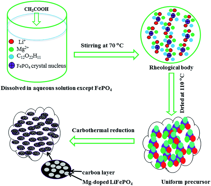 | ||
| Scheme 1 Illustration of the synthesis of the Mg-doped LiFePO4/C composite via carbon thermal reduction combined with rheological phase technology. | ||
From the SEM images of al-LFP and aq-LFP (Fig. 1), it can be seen that both samples present similar particle morphology consisting of oblate or ellipsoidal shapes with sizes ranging from 100 nm to 300 nm.
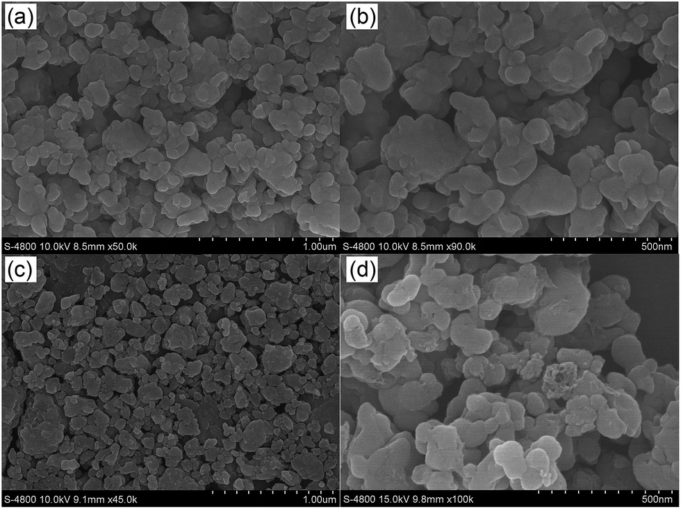 | ||
| Fig. 1 The SEM images of the (a and b) al-LFP and (c and d) aq-LFP samples. | ||
TEM/HRTEM images and elemental mapping images from scanning TEM and EDX of the aq-LFP sample were obtained (Fig. 2). The aq-LFP sample exhibits a primary crystallite size of 40–90 nm for the aq-LFP sample and a carbon layer of ∼3 nm thickness (Fig. 2a and b). The widths of the lattice fringes were about 3.92 Å, corresponding to the (210) planes of LFP crystals. The TEM/HRTEM images of the al-LFP sample are shown in Fig. S2.† The maps in Fig. 2c illustrate the uniformity of the dopants and coated carbon in the aq-LFP sample. A low amount of carbon is detected in the scanning region without sample powder, because the samples were previously deposited on copper grids coated with a lacey-carbon film. In addition, the energy-dispersive spectroscopy (EDS) results in Fig. 2d further confirm the Fe/P atomic ratio of ∼0.97:1 in the as-prepared sample. The excess amount of C element seen from Fig. 4d was due to the coated carbon film on the copper grids.
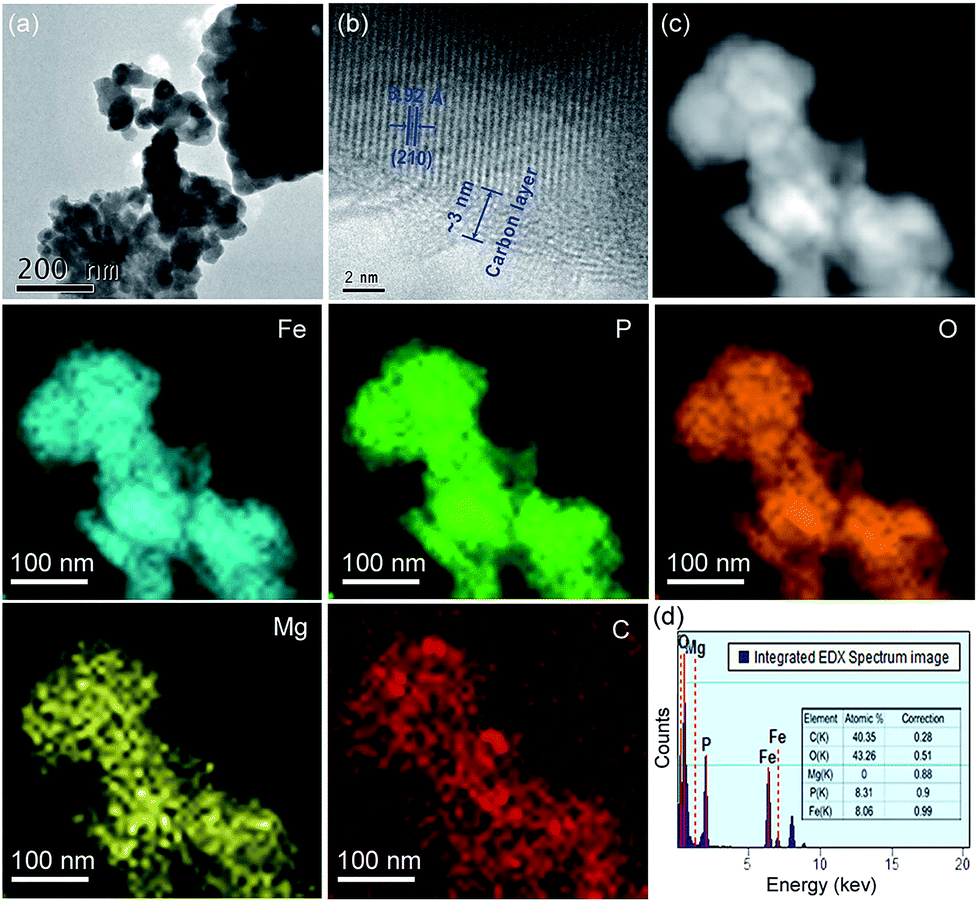 | ||
| Fig. 2 (a and b) TEM and (c) EDX elemental mapping images, and (d) element counts for the aq-LFP sample. | ||
In the XRD patterns, the diffraction peaks of the starting material FePO4·2H2O are well-indexed on the basis of a monoclinic structure (JCPDS no. 072-0471) (Fig. 3a). All the diffraction peaks in both the samples are consistent with the standard data of LiFePO4 (JCPDS no. 83-2092), indicating that the aqueous process using low cost precursors allows for synthesis of the same highly phase-pure LiFePO4 as the alcohol process. No additional diffraction peaks of related carbon or the doping Mg2+ are detected in the XRD pattern, suggesting an amorphous state of the residual carbon and a fractional amount of doping Mg2+. The amounts of residual carbon for the al-LFP and aq-LFP samples are 3.16 wt% and 3.23 wt%, analyzed using an automatic elemental analyzer. The XRD patterns of the samples were further analyzed using Rietveld refinements (Fig. 3b) and the results are listed in Table S1.† The reliability factors of Rwp from Table S1† are less than 7.2%, χ2 are less than 1.7%, and Rf are less than 4.6%, demonstrating that the results are reliable. The cell volumes of al-LFP and aq-LFP are 290.27 Å and 290.16 Å, respectively, which are smaller than the reported standard value of LiFePO4 (V = 291.4 Å3). Delacourt43 and Gibot44 reported that the unit-cell volume variations between the two end-members LiFePO4 (V = 291.4 Å3) and FePO4 (V = 272.4 Å3) possess linear extrapolation, namely follow Vegard’s law. Thus such unit-cell volumes of 290.27 Å (al-LFP) and 290.16 Å (aq-LFP) would correspond to LixFePO4 (x ≈ 0.94). This implies a Fe3+ content of ∼0.5 by the charge balance principle that a lithium deficiency in LiFePO4 can result in charge compensation by Fe3+. The results of the ICP analyses in Table S2† show that the as-prepared samples are Li-deficient compounds, namely, Li1−xFePO4 (0 ≤ x ≤ 0.02), despite the excess LiOH·H2O in the process of mixing the starting materials. This result provides a hint that lithium is likely to volatilize under the high-temperature firing conditions.14 In addition, the decrease in the Li content linked to an increase in Fe3+ indicates that Fe3+ exists in the as-prepared samples. Further information was obtained to verify the presence of reducible Fe3+ and the aq-LFP sample exhibits a more sloping curve (capacity of ∼10 mA h g−1 at 0.1C) in the 3.0–2.0 V voltage region, compared with the commercial LiFePO4 product (Fig. S3†). Such a sloping capacity corresponds to pyrophosphates somewhat lower in potential than LiFePO4.45,46 The surface elemental composition of both samples was determined using XPS (Fig. 3c and d). The Fe 2p3/2 and 2p1/2 binding energies of the peaks observed at ∼711 eV and ∼724 eV correspond to a Fe2+ valence state of iron. The Fe 2p3/2 and 2p1/2 peaks observed at ∼713 eV and ∼726 eV represent a Fe3+ valence state of iron.47 The results demonstrate the existence of a Fe3+ valence state of iron on the surface of the aq-LFP sample, which is in agreement with the presence of Fe3+ found in ICP analyses and Rietveld refinements.
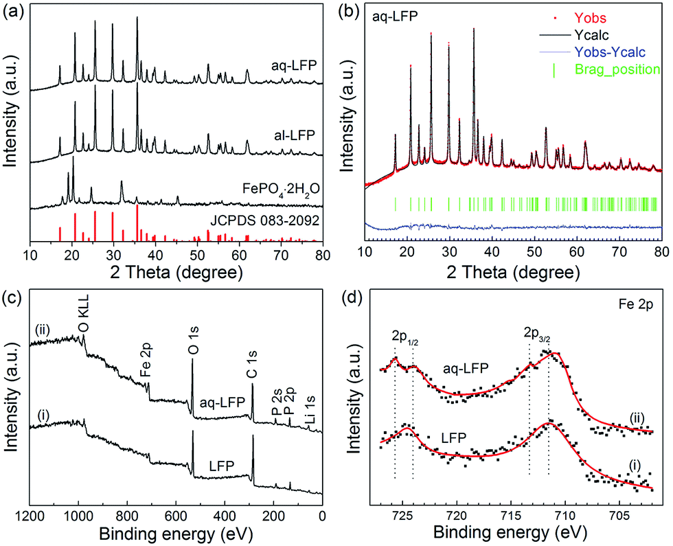 | ||
| Fig. 3 The (a) XRD patterns of the starting material FePO4·2H2O and as-prepared LiFePO4 samples, and (b) Rietveld refinement of the aq-LFP sample. XPS spectra: (c) survey spectra and (d) Fe 2p spectra of the commercial LiFePO4 product (LFP) and the aq-LFP sample. | ||
The nitrogen adsorption–desorption isotherms and the corresponding Barrett–Joyner–Halenda (BJH) pore size distribution curves of both the samples are provided (Fig. 4). Both the samples have the same type IV curve of the absorption–desorption isotherms with a large H3 hysteresis loop and a mesopore distribution (Fig. 4b), centered at 4 nm, indicating the existence of mesopores in both the samples.48 The al-LFP sample has a BET surface area of 16.5 m2 g−1 and an average pore width of 13.2 nm, and the aq-LFP sample has a BET surface area of 22.4 m2 g−1 with an average pore width of 13.9 nm. The higher BET surface area for the aq-LFP sample might be the result of the added acetic acid in the aqueous process, which formed a rheological phase slurry to result in a more uniform carbon distribution. The mesopores were probably generated from the expulsion of the gas (CO2), leaving small voids, which was formed from the reduction of FePO4 with sucrose.
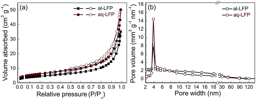 | ||
| Fig. 4 (a) Nitrogen adsorption (closed symbol)–desorption (open symbol) isotherms and (b) pore width distribution curves of the as-prepared LiFePO4 samples. | ||
In the discharge curves of the as-prepared samples, the specific capacity of the al-LFP sample reaches 158, 156, 150 and 141 mA h g−1 at 0.1C, 0.2C, 0.5C and 1C, respectively (Fig. 5a). The aq-LFP sample delivers a capacity of 158, 156, 152 mA h g−1 and 148 mA h g−1 at 0.1C, 0.2C, 0.5C and 1C, respectively. Considering that there is 3.2 wt% coated carbon in the material and 1.0 at% doped Mg, the capacity calculated from the LiFePO4 weight is 166 mA h g−1 at 0.1C, approximating the theoretical value of 170 mA h g−1. It can be obviously found that the aq-LFP sample has 6 mA h g−1 more capacity and a higher discharge potential plateau at the discharge rate of 1C than the al-LFP sample. This excellent rate capability of the aq-LFP sample could be attributed to improved conductivity resulting from the uniform element distribution and the Fe3+ surface phase generated through controlled off-stoichiometry. In order to evaluate the cycling performance of the as-prepared samples, the cells were charged and discharged at different rates from 0.1C to 1C stepwise in the first 8 cycles, and then cycled at 1C for 150 times. The cycling performances of the al-LFP and aq-LFP samples are presented in Fig. 5b. The aq-LFP sample exhibits better capacity (100%) retention than the al-LFP sample (97.6%), when cycled for 150 cycles at 1C.
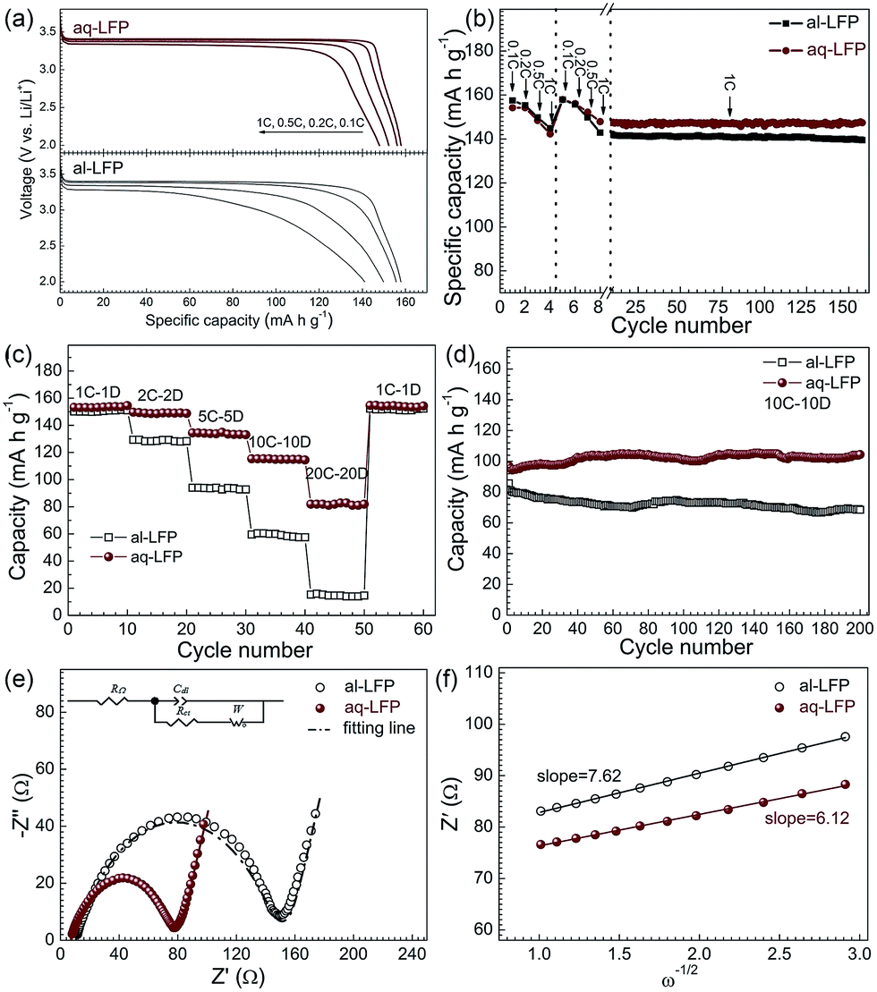 | ||
| Fig. 5 (a) Discharge curves, (b) charge–discharge recyclability at 1C, (c) rate performances, (d) charge–discharge recyclability at 10C, (e) electrochemical impedance spectra and the equivalent circuit (inset) of the as-prepared LiFePO4 samples and (f) the relationship plot between Zre and ω1/2 for the low-frequency region. | ||
At higher current rates of 2C–20C, aq-LEP exhibits more excellent rate and recyclability performances than al-LEP (Fig. 5c and d). The aq-LFP exhibited a better rate performance at high rates with discharge capacities of about 153, 149, 133, 115 and 81 mA h g−1 at 1C, 2C, 5C, 10C and 20C, respectively. The al-LFP exhibited high capacities of 150, 129, 94, 60 and 15 mA h g−1. It was found that al-LFP can deliver a discharge capacity of nearly 70 mA h g−1 at 10C after 200 cycles which is about 86% of the initial capacity. In contrast, aq-LFP exhibited a better cycling stability with a final discharge capacity of around 105 mA h g−1, which is 100% of the initial discharge capacity. The better electrochemical performance of aq-LFP is due to the high phase purity, the uniform element distribution, and the enhanced electronic conductivity resulting from the uniform carbon layer and Mg2+ doping distribution and the Fe3+ surface phase generated through controlled off-stoichiometry. In addition, the cathode formulation for the cells at low rates (from 0.1 to 1C) was prepared as for the industrial standard, just by mixing the active materials, conductive agent and PVDF in a weight ratio of 90:5:5, and with a loading of 15 mg cm−2. So the electrochemical results are directly comparable with that of the industrial product of LiFePO4 material. These results demonstrate that the LiFePO4 materials prepared using the cost-effective aqueous process possess a high reversible capacity and good rate capability, thus are easy to scale up.
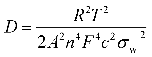
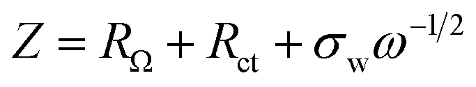
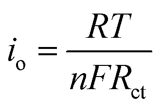
Fig. 5e shows the impedance spectra and a simplified equivalent circuit model (inset) for the al-LFP and aq-LFP samples, which were measured in the discharged state before charging. Fig. 5f shows the relationship plot between Zre and the reciprocal square root of the angular frequency (ω−1/2) for the low frequency region. The ohmic resistance (RΩ) represents the resistance of the electrolyte and electrode materials, corresponding to the intercept at the Z′ axis at high frequency. The semicircle in the middle frequency range presents the charge transfer resistance (Rct). The inclined line at low frequency indicates the Warburg impedance (Ws). The exchange current density (io) indicates the reversibility of the electrode. The corresponding parameters calculated using eqn (1)–(3) are recorded in Table 1. As seen from Table 1, the lithium-ion diffusion coefficient (DLi+) and the exchange current density (io) of the aq-LFP sample are 5.88 × 10⁻¹² cm2 s−1 and 3.75 × 10⁻⁴ mA cm−2 respectively, which are higher than for the al-LFP sample. This result indicates that enhanced electronic conductivity contributes to the electrochemical performance of LiFePO4 materials.
| Sample | RΩ (Ω) | Rct (Ω) | σw (Ω cm2 s−0.5) | D (cm2 s−1) | io (mA cm−2) |
|---|---|---|---|---|---|
| al-LFP | 10.47 | 135.5 | 7.62 | 3.39 × 10⁻¹² | 1.90 × 10⁻⁴ |
| aq-LFP | 6.80 | 68.5 | 6.12 | 5.88 × 10⁻¹² | 3.75 × 10⁻⁴ |
The lithium-ion diffusion coefficient was calculated using the following equation:49,50
 | (1) |
 | (2) |
The exchange current density (io) of the as-prepared LiFePO4 samples was calculated from the equation:
 | (3) |
4. Conclusions
In conclusion, fine LiFePO4 powders with uniform element distributions were obtained using an aqueous process combined with rheological phase technology. The uniform distribution is attributed to homogeneous mixing of the starting materials containing sucrose, LiOH·H2O and Mg(CH3COO)2·4H2O. Rietveld refinements, ICP analyses and XPS data demonstrated that a Fe3+ valence state of iron exists in the as-prepared sample, which is beneficial for improvement of the rate capability. The aq-LFP sample exhibits a discharge capacity of 148 mA h g−1 and potential plateau of 3.32 V at 1C. Approximately 100% capacity retention is maintained after 150 cycles at 1C or 200 cycles at 10C. The excellent rate capability and cycling stability are mainly attributed to improved conductivity resulting from the uniform element distribution and the Fe3+ surface phase generated through controlled off-stoichiometry. The aqueous preparation process combined with rheological phase technology improves the uniformity and stability from the process of mixing the starting materials, and reduces manufacturing cost. This aqueous process combined with rheological phase technology is easy to scale up for the industrial production of LiFePO4 cathode materials.Acknowledgements
Financial support from the National Natural Science Foundation of China (no. U1204203 and 21401168) and the Outstanding Young Teacher Development Fund of Zhengzhou University (no. 1421316037) is acknowledged. We thank Henan Dilong T & D Co., Ltd for their assistance with electrode preparation. We also thank Prof. Huaqiang Cao for his useful discussion.Notes and references
- D. MacNeil, Z. Lu, Z. Chen and J. R. Dahn, J. Power Sources, 2002, 108, 8 CrossRef CAS.
- M. Takahashi, S.-.i Tobishima, K. Takei and Y. Sakurai, Solid State Ionics, 2002, 148, 283 CrossRef CAS.
- A. K. Padhi, K. S. Nanjundaswamy and J. B. Goodenough, J. Electrochem. Soc., 1997, 144, 1188 CrossRef CAS PubMed.
- S. F. Yang, Y. N. Song, P. Y. Zavalij and M. S. Whittingham, Electrochem. Commun., 2002, 4, 239 CAS.
- A. Yamada, M. Hosoya, S. C. Chung, Y. Kudo, K. Hinokuma, K. Y. Liu and Y. Nishi, J. Power Sources, 2003, 119, 232 CrossRef.
- X. Lou and Y. Zhang, J. Mater. Chem., 2011, 21, 4156 RSC.
- F. Yu, J. J. Zhang, Y. F. Yang and G. Z. Song, J. Power Sources, 2010, 195, 6873 CrossRef CAS PubMed.
- K. S. Park, S. B. Schougaard and J. B. Goodenough, Adv. Mater., 2007, 19, 848 CrossRef CAS PubMed.
- N. Ravet, Y. Chouinard, J. Magnan, S. Besner, M. Gauthier and M. Armand, J. Power Sources, 2001, 97, 503 CrossRef.
- N. Ravet, J. Goodenough, S. Besner, M. Simoneau, P. Hovington and M. Armand, 196th Meeting of the Electrochemical Society, Hawai, 1999 Search PubMed.
- S. Franger, F. le Cras, C. Bourbon and H. Rouault, Electrochem. Solid-State Lett., 2002, 5, A231 CrossRef CAS PubMed.
- B. Wang, B. Xu, T. Liu, P. Liu, C. Guo, S. Wang, Q. Wang, Z. Xiong, D. Wang and X. S. Zhao, Nanoscale, 2014, 6, 986 RSC.
- B. Jin, E. M. Jin, K. H. Park and H. B. Gu, Electrochem. Commun., 2008, 10, 1537 CrossRef CAS PubMed.
- S. Y. Chung, J. T. Bloking and Y. M. Chiang, Nat. Mater., 2002, 1, 123 CrossRef CAS PubMed.
- H. Liu, Q. Cao, L. J. Fu, C. Li, Y. P. Wu and H. Q. Wu, Electrochem. Commun., 2006, 8, 1553 CrossRef CAS PubMed.
- Y. C. Ge, X. D. Yan, J. Liu, X. F. Zhang, J. W. Wang, X. G. He, R. S. Wang and H. M. Xie, Electrochim. Acta, 2010, 55, 5886 CrossRef CAS PubMed.
- L. Fu, H. Liu, C. Li, Y. Wu, E. Rahm, R. Holze and H. Wu, Prog. Mater. Sci., 2005, 50, 881 CrossRef CAS PubMed.
- D. Choi and P. N. Kumta, J. Power Sources, 2007, 163, 1064 CrossRef CAS PubMed.
- C. Miao, P. F. Bai, Q. Q. Jiang, S. Q. Sun and X. Y. Wang, J. Power Sources, 2014, 246, 232 CrossRef CAS PubMed.
- J. Mosa, M. Aparicio, A. Duran, C. Laberty-Robert and C. Sanchez, J. Mater. Chem. A, 2014, 2, 3038 CAS.
- Y. Long, Y. Shu, X. H. Ma and M. X. Ye, Electrochim. Acta, 2014, 117, 105 CrossRef CAS PubMed.
- M. Lin, Y. Chen, B. Chen, X. Wu, K. Kam, W. Lu, H. L. Chan and J. Yuan, ACS Appl. Mater. Interfaces, 2014, 6, 17556 CAS.
- S. P. Wang, H. X. Yang, L. J. Feng, S. M. Sun, J. X. Guo, Y. Z. Yang and H. Y. Wei, J. Power Sources, 2013, 233, 43 CrossRef CAS PubMed.
- D. Jugovic and D. Uskokovic, J. Power Sources, 2009, 190, 538 CrossRef CAS PubMed.
- L. F. Cheng, G. X. Liang, S. El Khakani and D. D. MacNeil, J. Power Sources, 2013, 242, 656 CrossRef CAS PubMed.
- C. Chen, G. B. Liu, Y. Wang, J. L. Li and H. Liu, Electrochim. Acta, 2013, 113, 464 CrossRef CAS PubMed.
- Z. Feng, C. Zhang, J. Chen, Y. Wang, X. Jin, R. Zhang and J. Hu, RSC Adv., 2013, 3, 4408 RSC.
- J. C. Zheng, X. H. Li, Z. X. Wang, H. J. Guo and S. Y. Zhou, J. Power Sources, 2008, 184, 574 CrossRef CAS PubMed.
- C. H. Mi, X. B. Zhao, G. S. Cao and J. P. Tu, J. Electrochem. Soc., 2005, 152, A483 CrossRef CAS PubMed.
- G. Amold, J. Garche, R. Hemmer, S. Ströbele, C. Vogler and M. Wohlfahrt-Mehrens, J. Power Sources, 2003, 119, 247 Search PubMed.
- B. Wang, Y. Qiu and S. Ni, Solid State Ionics, 2007, 178, 843 CrossRef CAS PubMed.
- Y. Cao, L. Yu, T. Li, X. Ai and H. Yang, J. Power Sources, 2007, 172, 913 CrossRef CAS PubMed.
- L. N. Wang, Z. G. Zhang and K. L. Zhang, J. Power Sources, 2007, 167, 200 CrossRef CAS PubMed.
- K. R. Yang, Z. J. Lin, X. B. Hu, Z. H. Deng and J. S. Suo, Electrochim. Acta, 2011, 56, 2941 CrossRef CAS PubMed.
- N. Y. Gu, H. Wang, Y. Li, H. Y. Ma, X. H. He and Z. Y. Yang, J. Solid State Electrochem., 2014, 18, 771 CrossRef CAS.
- C.-C. Li, Y.-H. Wang and T.-Y. Yang, J. Electrochem. Soc., 2011, 158, A828 CrossRef CAS PubMed.
- Y. G. Wang, Y. R. Wang, E. J. Hosono, K. X. Wang and H. S. Zhou, Angew. Chem., Int. Ed., 2008, 47, 7461 CrossRef CAS PubMed.
- K. Yang, Z. Deng and J. Suo, J. Power Sources, 2012, 201, 274 CrossRef CAS PubMed.
- Y. Wang, J. Wang, J. Yang and Y. Nuli, Adv. Funct. Mater., 2006, 16, 2135 CrossRef CAS PubMed.
- L. Ni, J. G. Zheng, C. C. Qin, Y. W. Lu, P. X. Liu, T. F. Wu, Y. F. Tang and Y. F. Chen, Electrochim. Acta, 2014, 147, 330 CrossRef CAS PubMed.
- H. J. Kim, J. M. Kim, W. S. Kim, H. J. Koo, D. S. Bae and H. S. Kim, J. Alloys Compd., 2011, 509, 5662 CrossRef CAS PubMed.
- B. Wang, D. L. Wang, Q. M. Wang, T. F. Liu, C. F. Guo and X. S. Zhao, J. Mater. Chem. A, 2013, 1, 135 CAS.
- C. Delacourt, J. Rodriguez-Carvajal, B. Schmitt, J. M. Tarascon and C. Masquelier, Solid State Sci., 2005, 7, 1506 CrossRef CAS PubMed.
- P. Gibot, M. Casas-Cabanas, L. Laffont, S. Levasseur, P. Carlach, S. Hamelet, J. M. Tarascon and C. Masquelier, Nat. Mater., 2008, 7, 741 CrossRef CAS PubMed.
- A. K. Padhi, K. S. Nanjundaswamy, C. Masquelier, S. Okada and J. B. Goodenough, J. Electrochem. Soc., 1997, 144, 1609 CrossRef CAS PubMed.
- B. Kang and G. Ceder, Nature, 2009, 458, 190 CrossRef CAS PubMed.
- L. Castro, R. Dedryvere, J. B. Ledeuil, J. Breger, C. Tessier and D. Gonbeau, J. Electrochem. Soc., 2012, 159, A357 CrossRef CAS PubMed.
- Y. Ren and P. G. Bruce, Electrochem. Commun., 2012, 17, 60 CrossRef CAS PubMed.
- W. Liu, J. Tu, Y. Qiao, J. Zhou, S. Shi, X. Wang and C. Gu, J. Power Sources, 2011, 196, 7728 CAS.
- H. Shu, X. Wang, Q. Wu, B. Ju, L. Liu, X. Yang, Y. Wang, Y. Bai and S. Yang, J. Electrochem. Soc., 2011, 158, A1448 CrossRef CAS PubMed.
Footnote |
| † Electronic supplementary information (ESI) available: TGA experiment of FePO4·2H2O, TEM images of the al-LFP, other battery discharge/charge tests, detailed calculations of the XRD Rietveld refinements, and ICP information. See DOI: 10.1039/c5ra11680e |
| This journal is © The Royal Society of Chemistry 2015 |