
Hierarchical polystyrene@reduced graphene oxide–Pt core–shell microspheres for non-enzymatic detection of hydrogen peroxide†
Weilu Liua,
Cong Lib,
Peng Zhanga,
Liu Tangb,
Yue Gub,
Yujing Zhanga,
Jianqing Zhanga,
Zhongbo Liua,
Guoxiang Sun*a and
Zhiquan Zhang*b
aSchool of Pharmacy, Shenyang Pharmaceutical University, Shenyang 110016, PR China. E-mail: gxswmwys@163.com
bCollege of Chemistry, Jilin University, Changchun 130012, PR China. E-mail: zzq@jlu.edu.cn
First published on 24th August 2015
Abstract
A non-enzymatic electrochemical sensor based on polystyrene@reduced graphene oxide (RGO)–Pt core–shell microspheres was developed for sensitive detection of hydrogen peroxide (H2O2). The polystyrene@RGO–Pt microspheres were prepared by microwave-assisted reduction of graphene oxide (GO) and a Pt precursor (H2PtCl6) that were adsorbed on polystyrene microspheres. No surfactants or polyelectrolytes were used as stabilizing agents for the preparation of the nanocomposite. Alternatively, polystyrene microspheres served as the core for supporting RGO nanosheets and Pt nanoparticles, which prevented the aggregation of the electrode material and resulted in the high electrochemically active surface area. Scanning electron microscopy (SEM), transmission electron microscopy (TEM), energy dispersive X-ray spectroscopy (EDS), X-ray photoelectron spectroscopy (XPS), X-ray diffraction (XRD), Raman spectroscopy, Fourier transform infrared spectroscopy (FT-IR), Ultraviolet-vis absorption spectroscopy (UV), and Brunauer–Emmett–Teller (BET) measurements characterized the nanostructure of the polystyrene@RGO–Pt microspheres. Cyclic voltammetry revealed the enhanced electrocatalytic activity of these core–shell microspheres. Such a non-enzymatic electrochemical sensor is capable of detecting H2O2 with a wide linear range (0.5 μM–8000 μM), high sensitivity (38.57 μA mM−1 cm−2), low detection limit (0.1 μM, S/N = 3), long-term stability, and good selectivity. Furthermore, this sensor was found to be suitable for the determination of H2O2 in human serum samples. Considering their simple synthetic procedure and high catalytic activity, the polystyrene@RGO–Pt microspheres hold great promise in the development of high performance electrochemical sensors.
1. Introduction
Hydrogen peroxide (H2O2) is an important reactive oxygen species (ROS) that is involved in several biological processes such as vascular remodeling, immune cell activation, stomatal closure and root growth.1,2 H2O2 is also a product of glucose oxidation in the presence of glucose oxidase and oxygen.3 Glucose content can be measured indirectly through the detection of hydrogen peroxide. Thus, monitoring the H2O2 level is of practical significance in biochemical, pharmaceutical, clinical, environmental, and industrial research. Among the various developed methods (e.g., chemiluminescence,4 fluorescence5), electrochemical sensors have received considerable attention due to their advantages of being simple, rapid, sensitive, and cost effective.6,7 Current electrochemical sensors often rely on the use of biological enzymes (e.g., hemoglobin,8 horseradish peroxidase,9 and cytochrome c10). Despite the high selectivity and low detection limit, the enzyme sensors bear poor long-term stability and poor tolerance in experimental conditions. Alternatively, non-enzymatic sensors are good candidates for H2O2 detection due to the advantages of high stability, high electrocatalytic ability, and simplicity.11–18 However, many electrode materials suffer from slow electrode kinetics and high overpotential for detection, which may cause severe interference from other molecules.19 Thus, it is meaningful to develop novel electrode materials for the fabrication of non-enzymatic H2O2 sensors with improved sensing ability.Reduced graphene oxide (RGO), a two-dimensional single atomic planar sheet of sp2 bonded carbon atoms, has received much attention in the fabrication of electrochemical sensors and biosensors.20–22 The advantages such as high surface area, super conductivity and wide potential window of RGO enable it to improve the detection efficiency in terms of accelerating electron transfer rate and enhancing sensitivity.23–25 Besides, Pt nanoparticles (PtNPs) also exhibit electrocatalytic behavior towards H2O2 and have been widely used in sensors.26–29 The decoration of PtNPs with RGO nanosheet will accelerate the detection efficiency by inducing specific microstructures or modifying the electron density in the resultant nanocomposite.19,30,31 For instance, Lin et al. reported that poly(diallyldimethylammonium chloride) functionalized RGO/Pt nanocomposite exhibited excellent catalytic activity towards formic acid oxidation.32 Wang et al. reported nanocomposite of Pt nanoparticles and polydopamine-coated RGO for the electrochemical catalysis of oxygen reduction.33 Yuan et al. reported platinum–palladium–chitosan–RGO hybrid nanocomposites for detection of cholesterol.34 Choi et al. reported the synthesis of RGO–poly(sodium styrene sulfonate)–Pt nanocomposite and its application in methanol oxidation reaction.35 These reports reveal the remarkable electrocatalytic ability of RGO/Pt nanocomposite and its potentiality in the development of electrochemical sensors.
It is noticed in these reports that RGO/Pt nanocomposites are dispersed in solutions with the aid of surfactants or polyelectrolytes such as poly(diallyldimethylammonium chloride), chitosan, and poly(sodium styrene sulfonate). The use of surfactants or polyelectrolytes exists disadvantages such as introducing additional diffusion resistance and blockage of certain active sites, which may increase the overpotential of the electrochemical reactions. Moreover, the synthesis process that using surfactants or polyelectrolytes is tedious and time-consuming. Thus, surfactant-free synthetic methods are desired for preparing RGO/Pt nanocomposite.
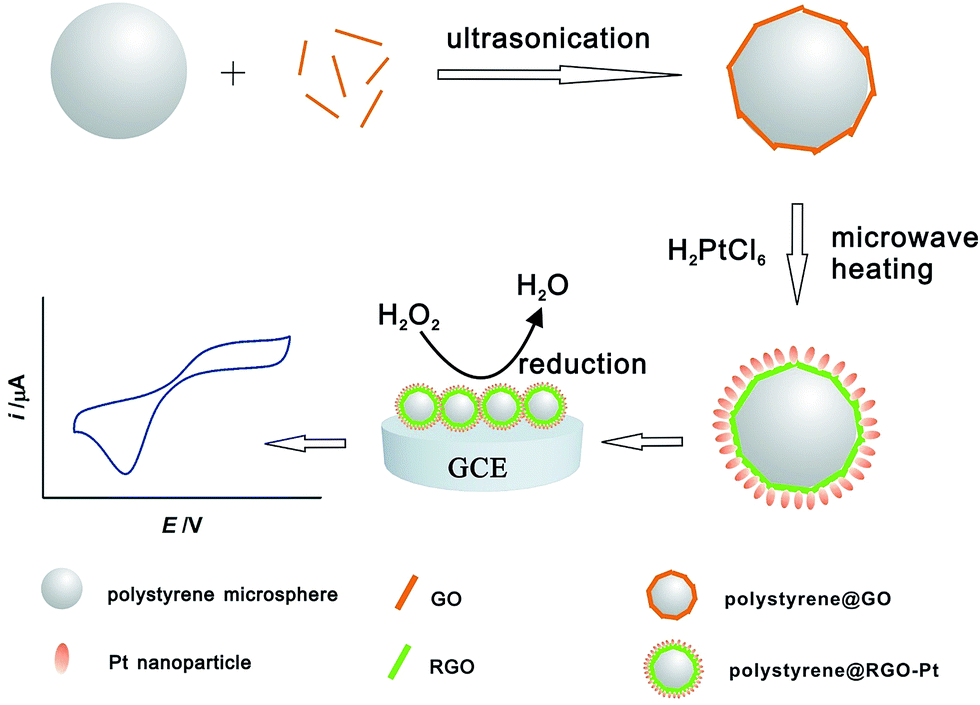
In this work, a microwave-assisted method was employed for the facile synthesis of polystyrene@RGO–Pt core–shell microspheres. No surfactants or polyelectrolytes were employed in the synthesis process, and the electrode material was given full pay to its catalytic activity. Polystyrene microspheres served as the core for supporting RGO and Pt nanoparticles. The aggregation of the nanomaterial was effectively prevented, and the resultant microspheres exhibits extremely high electrochemically active surface area. An enhanced reduction peak current and low overpotential for the reduction of H2O2 were achieved on polystyrene@RGO–Pt microspheres modified electrode. Moreover, the wide linear detection range, low detection limit, high sensitivity and fast response of the electrode, along with the applicability in human serum samples, made this electrode promising as an effective non-enzymatic H2O2 sensor.
2. Experimental section
2.1. Preparation of polystyrene@RGO–Pt core–shell microspheres
Polystyrene microspheres were prepared according to the literature.36 Graphite oxide was synthesized from natural graphite powder (Qingdao Hengrui Industrial) using the modified Hummers method.37 Exfoliation of graphite oxide to graphene oxide (GO) was achieved by ultrasonication of the dispersion for 30 min.The synthesis process of polystyrene@RGO–Pt is shown in Scheme 1. Firstly, 0.5 mg polystyrene microspheres were dispersed into 20 mL ethylene glycol/water (1/1, v/v) solution, followed by the addition of 0.1 mL GO (4 mg mL−1) and ultrasonication, which resulted in the nanostructure of polystyrene@GO microspheres. Then, 0.1 mL Pt precursor (H2PtCl6, 77 mM) was added into the polystyrene@GO suspension. After being vigorously shaken, the above mixture was heated 2 minutes in a household microwave oven that is equipped with a voltage stabilizer (Panasonic, power: 1000 W, 40% of the power was used, SFig. 1 in ESI†). Herein, ethylene glycol plays a role of reducing agent for the reduction of GO and H2PtCl6 according to the literature.38 The resultant black product was isolated by centrifugation at 6000 rpm for 15 minutes, followed by consecutive washing/centrifugation cycles two times with water. The collected product was redispersed readily in water/ethanol mixture to produce a colloidal polystyrene@RGO–Pt microspheres suspension. As a comparison, polystyrene@RGO and polystyrene@Pt was synthesized with the above procedure.
 | ||
| Scheme 1 The synthesis process of polystyrene@RGO–Pt. | ||
The synthesis process was repeated three times to demonstrate the reliability of this method. Ultraviolet-vis (UV) absorption spectroscopy was used to monitor the microwave-assisted reduction reaction (SFig. 2 in ESI†). The suspension of polystyrene@GO exhibited an absorption peak at 231 nm. After the microwave heating, the absorption peaks of all the products shifted to 268 nm, indicating the reduction of GO to RGO39 and the reliability of the synthetic method.
The polystyrene@RGO–Pt microspheres suspension was dropped on the electrode surface as catalyst for the reduction of H2O2. Prior to modification, the glassy carbon electrode (GCE) was polished with 1, 0.3 and 0.05 μm alumina slurry, respectively. The GCE was washed successively with 1![[thin space (1/6-em)]](https://www.rsc.org/images/entities/char_2009.gif) :1 nitric acid, acetone and water. Then, 5 μL polystyrene@RGO–Pt microspheres suspension was carefully dropped on the cleaned GCE surface and dried in atmosphere environment.
:1 nitric acid, acetone and water. Then, 5 μL polystyrene@RGO–Pt microspheres suspension was carefully dropped on the cleaned GCE surface and dried in atmosphere environment.
2.2. Characterizations
The polystyrene@RGO–Pt core–shell microspheres were characterized by field-emission scanning electron microscopy (SEM, Hitachi S-4800), field emission transmission electron microscopy (TEM, FEI TecnaiG2 F20 s-twin D573 with an accelerating voltage of 200 kV) equipped with energy dispersive X-ray spectroscopy (EDS), X-ray photoelectron spectroscope (XPS, ESCALAB-MKII 250 photoelectron spectrometer, VG Co.), X-ray diffraction (XRD, CuKα radiation, D/max2550VB, Rigaku), Raman spectroscopy (Horiba Jobin Yvon T64000 system with 514.5 nm radiations), Fourier transform infrared spectroscopy (FT-IR, Bruker IFS55), Brunauer–Emmett–Teller (BET) surface area analyzer (Micromeritics ASAP-2020M automatic volumetric instrument), Ultraviolet-vis absorption spectroscopy (UV, UV-1700 Shimidazule), and Electrochemical workstation (CHI760d).2.3. Electrochemical measurements
A three-electrode cell was employed for the electrochemical measurement of H2O2. A glassy carbon electrode (diameter: 3 mm, geometric electrode surface area: 0.07 cm2) was used as the working electrode, a platinum wire was used as the counter electrode, and an Ag/AgCl electrode (KCl saturated) was used as the reference electrode. All potentials in the text are with respect to the Ag/AgCl reference electrode. Cyclic voltammograms (CVs) and amperometric i–t curves were obtained in Phosphate Buffered Saline (PBS, pH 7.0) with spiked H2O2.3. Results and discussion
3.1 Polystyrene@RGO–Pt microspheres
The resultant polystyrene@RGO–Pt microspheres were analyzed by SEM, TEM, EDS, XPS, XRD, Raman, FT-IR, and BET measurement. Fig. 1 shows the SEM images of polystyrene microsphere, polystyrene@GO microsphere, and polystyrene@RGO–Pt microsphere, respectively. Fig. 1A depicts that the surface of polystyrene microspheres is smooth. After anchored with GO, the surface of microsphere became wrinkled (Fig. 1B). GO nanosheets can attached onto the surface of polystyrene microsphere via π–π interaction.40–43 In the microwave-assisted heating process, most of the oxygen group on GO were removed, and Pt precursor (H2PtCl6) were reduced to Pt nanoparticles and attached on the microspheres. Fig. 1C exhibits the resultant core–shell nanostructure of polystyrene@RGO–Pt microspheres. Pt nanoparticles were uniformly distributed on the surface of microsphere. Polystyrene microsphere served as the core for supporting RGO nanosheets and Pt nanoparticles, which effectively prevented the aggregation of the nanomaterials. Although no surfactants or polyelectrolytes were used in the synthesis progress, highly dispersed polystyrene@RGO–Pt microspheres with a small size distribution were observed in a low magnification SEM image (Fig. 1D). Their average size, measured from 100 microspheres, was ca. 580 nm.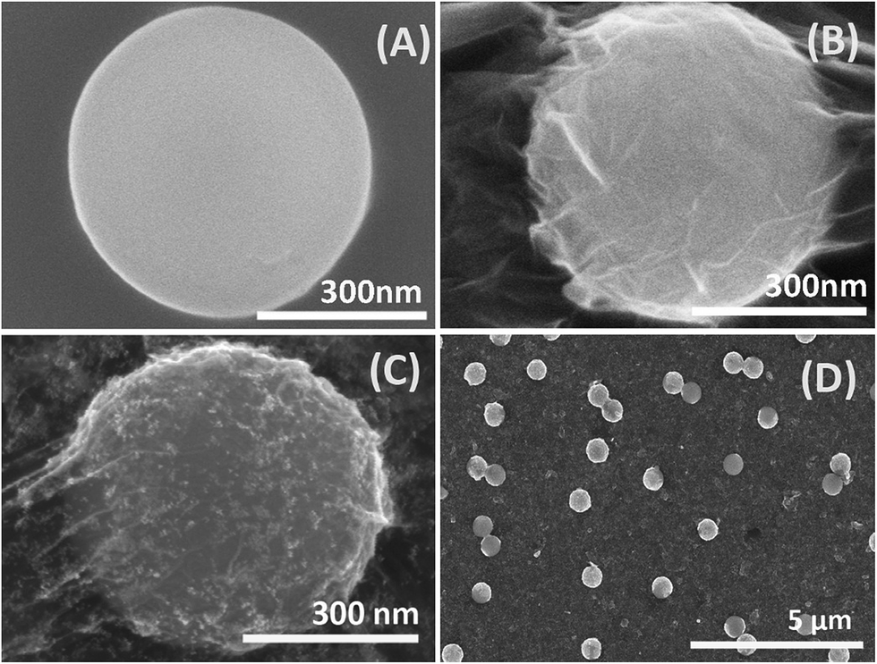 | ||
| Fig. 1 SEM images of polystyrene microsphere (A), polystyrene@GO microsphere (B), polystyrene@RGO–Pt microsphere (C), and large scale view of polystyrene@RGO–Pt microsphere (D). | ||
Fig. 2A and Fig. 2B reveal the typical TEM images of polystyrene@RGO–Pt microspheres. The core–shell nanostructure is obviously visible. The inner core represents polystyrene microsphere. The wrinkled shell, that attached on the surface of the core, is composed of RGO–Pt nanocomposite. The thickness of the shell was about in the range from 20 nm to 43 nm. The magnified image at the edge of the shell reveals the nanostructure of RGO–Pt nanocomposite (Fig. 2C). High loading of Pt nanoparticles on RGO nanosheets was observed. High resolution TEM image (Fig. 2D) indicates that the mean diameter of the Pt nanoparticles, measured from 50 microspheres, is estimated as ca. 3.4 nm. The measured interplanar spacing for the lattice fringes is 2.28 Å, which corresponds to the (111) lattice plane of face-centered cubic (fcc) Pt. This TEM analysis demonstrated the core–shell nanostructure of the polystyrene@RGO–Pt microspheres. Moreover, the high resolution TEM image on the edge of RGO indicates that the layer number of RGO was about 5–6 layers (SFig. 3 in ESI†). The composition of the polystyrene@RGO–Pt microspheres was further characterized by energy dispersive X-ray spectroscopy (EDS). The EDS spectrum (Fig. 2E) shows the peaks that corresponding to C, Pt, Cu, O, and Si elements, confirming the composition of polystyrene@RGO–Pt microspheres.
 | ||
| Fig. 2 Typical TEM images of polystyrene@RGO–Pt microspheres (A) and (B). The magnified TEM image at the edge of polystyrene@RGO–Pt microspheres (C). High resolution TEM image of Pt nanoparticles on polystyrene@RGO–Pt microspheres (D). The EDS spectrum of polystyrene@RGO–Pt microspheres (E). | ||
XPS was performed for the characterization of polystyrene@RGO–Pt microspheres. The C1s deconvolution spectrum were used to illustrate the formation of RGO. In Fig. 3A, the three peaks that centered at 284.7, 286.7, and 288.6 eV correspond to C–C in aromatic rings, C–O (epoxy and alkoxy), and O–C![[double bond, length as m-dash]](https://www.rsc.org/images/entities/char_e001.gif) O in GO, respectively.44 In Fig. 3B, the intensities of all C1s peaks of the carbon binding to oxygen, especially the peak of C–O (epoxy and alkoxy), decreased dramatically, indicating that most of the oxygen-containing functional groups were removed after the microwave-assisted reduction. So it is inferred that GO was reduced to RGO. Fig. 3C exhibits two peaks at 71.6 and 75.1 eV that correspond to the Pt 4f7/2 and Pt 4f5/2 binding energy, respectively.45 They are assigned to the metallic Pt(0) state and indicated the presence of Pt element in polystyrene@RGO–Pt microspheres.
O in GO, respectively.44 In Fig. 3B, the intensities of all C1s peaks of the carbon binding to oxygen, especially the peak of C–O (epoxy and alkoxy), decreased dramatically, indicating that most of the oxygen-containing functional groups were removed after the microwave-assisted reduction. So it is inferred that GO was reduced to RGO. Fig. 3C exhibits two peaks at 71.6 and 75.1 eV that correspond to the Pt 4f7/2 and Pt 4f5/2 binding energy, respectively.45 They are assigned to the metallic Pt(0) state and indicated the presence of Pt element in polystyrene@RGO–Pt microspheres.
 | ||
| Fig. 3 XPS C1s spectra of polystyrene@GO (A), and polystyrene@RGO–Pt (B). XPS Pt 4f spectra of polystyrene@RGO–Pt (C). (D) XRD patterns of graphite (curve-a), GO (curve-b), and polystyrene@RGO–Pt (curve-c). | ||
XRD patterns of the electrode materials were recorded in Fig. 3D. For graphite (curve-a), a sharp peak at 26.3° that corresponding to C(002) plane is observed due to the good crystallinity of graphite. The d-spacing is calculated as 0.34 nm according to Bragg equation. Curve-b represents the XRD patterns of GO that obtained by the oxidation of graphite using the modified Hummers method. It is observed that the C(002) peak shifts to 12.3° and the interlayer spacing was increased to 0.72 nm. The increment of the interlayer spacing is mainly caused by the oxygen functional groups on GO. Curve-c reveals the XRD patterns of the resultant polystyrene@RGO–Pt microspheres that obtained from the microwave-assisted reduction. It is observed the C(002) peak at 12.3° that corresponding to GO was almost disappeared, and the very tiny and wide C(002) peak at about 28.6° was ascribed to RGO nanosheet on the microspheres. The disappearance of the C(002) peak at 12.3° indicates that GO has been reduced to RGO46 by this microwave-assisted reduction. Moreover, the peaks found at 39.8°, 46.3°, 67.6°, 81.4° are assigned to the Pt(111) (200) (220) (311) faces, respectively (PDF#87-0646), which demonstrate the Pt nanoparticles on the microspheres.
Raman spectroscopy was used to further characterize the resultant polystyrene@RGO–Pt microspheres. The electrode materials show primary peaks centered at ∼1350 cm−1 (D band), ∼1591 cm−1 (G band), and ∼2691 cm−1 (2D band) (Fig. 4A). The D band is usually attributed to the disorder and imperfection of the carbon crystallites, the G band is ascribed to the E2g phonon of C sp2 atoms, and the 2D band is a second order vibration caused by the scattering of phonons at the zone boundary.47–49 The intensity ratio of the D band to G band (ID/IG) in the Raman spectrum corresponds to the extent of disorder in the graphitic carbon.50 The ID/IG ratio of polystyrene@RGO–Pt is 1.07, higher than that of GO (0.79). This increase of ID/IG ratio inferring that polystyrene@RGO–Pt has a lower graphitic crystalline structure, which is caused by deoxygenation of GO in the microwave assisted reduction. During the reduction process, the oxygen functional groups in GO can be partially removed, and the conjugated RGO network (sp2 carbon) will be reestablished. Nevertheless, the size of the reestablished RGO network is smaller than the original ones, which leads to the increasing extent of disorder and a larger ID/IG value of polystyrene@RGO–Pt.51 Therefore, the change in the ID/IG ratio demonstrate the reliability of the microwave assisted reduction method for the preparation of polystyrene@RGO–Pt. Furthermore, the position and shape of the 2D band can be used to distinguish the layer numbers of RGO. The broad 2D band at 2691 cm−1 indicated that the layer number is about 5 layers,52,53 which is consistent with the TEM results (SFig. 3 in ESI†).
 | ||
| Fig. 4 (A) Raman spectra of GO (curve-a) and polystyrene@RGO–Pt (curve-b). (B) FT-IR spectra of GO (curve-a), polystyrene@RGO–Pt (curve-b), and polystyrene sphere (curve-c). | ||
Fig. 4B shows the FT-IR spectra of the electrode materials. Curve-a indicates the presence of the oxygen-containing functional groups on GO. The wide peak at about 3447 cm−1 is attributed to the hydroxyl stretching vibration of C–OH groups, and the peak at about 1394 cm−1 corresponds to the hydroxyl bending vibration of C–OH groups.54 The peak at about 1727 cm−1 is due to the CO stretching in carboxyl group, and the peak at 1644 cm−1 is assigned to carbon skeleton (CC/C–C).55 The peak at 1104 cm−1 is ascribed to carboxy C–O or alkoxy C–O.56 As for polystyrene@RGO–Pt (curve-b), the intensity of the peaks related to the oxygen-containing functional groups are found to be decreased, indicating that most of the oxygen functional groups were removed by the microwave-assisted reduction. Typical polystyrene sphere absorption bands at 3027, (2925 and 2852), (1602, 1500, and 1451), (1076 and 1029), (765 and 698) cm−1 were observed in curve-c. These peaks are attributed to stretching vibration of C–H, stretching vibration of –CH2–, stretching vibration of aromatic CC, in-plane bending vibration of C–H, and out-of-plane bending vibration of C–H (monosubstituted ring).41,42 The main characterization peaks of polystyrene sphere were found in curve-b, confirming the attachment of RGO on polystyrene spheres in the resultant product of polystyrene@RGO–Pt.
N2 adsorption measurement (Fig. 5) was conducted to investigate the BET surface area of polystyrene@RGO–Pt microspheres. Ultrahigh-purity-grade N2 gas was used in the adsorption measurement. The N2 isotherm was measured using a liquid nitrogen bath (77 K). The BET surface area was calculated to be 31.82 m2 g−1.
 | ||
| Fig. 5 N2 adsorption–desorption isotherm of polystyrene@RGO–Pt microspheres. | ||
Polystyrene@RGO–Pt microspheres modified GCE was subjected to cyclic voltammetry in H2SO4 to determine the electrochemically active surface area (ECSA). ECSA represents the number of available active sites for electrocatalysis and electron transfer at the electrode surface. The cyclic voltammograms in Fig. 6 shows two well-defined peaks in the potential range from −0.20 to 0.10 V. The cathodic and anodic peaks are due to hydrogen adsorption/desorption processes. The integration of both cathodic and anodic peaks quantifies the activity of platinum sites for hydrogen adsorption and desorption. ECSA can be determined by charge integration (QH (μC)) of the hydrogen adsorption and desorption peaks of the cyclic voltammogram following the equation.57
| ECSA (Pt) = QH/210 (μC cm−2) |
 | ||
| Fig. 6 Cyclic voltammogram at polystyrene@RGO–Pt microspheres modified GCE in 0.5 M H2SO4 at a scan rate of 50 mV s−1. | ||
3.2 Electrochemical reduction of H2O2
The electrocatalytic behavior of polystyrene@RGO–Pt modified GCE towards H2O2 reduction was investigated using cyclic voltammetry. Polystyrene@RGO modified GCE and polystyrene@Pt modified GCE were also constructed for comparison. Fig. 7A shows cyclic voltammograms of different electrodes in N2-saturated PBS (pH 7.0) containing 5 mM H2O2. Reduction peaks can be observed within the potential window from −0.4 to 1.0 V. Whereas no oxidation peaks are visible in the reverse potential scan, suggesting that H2O2 undergo an irreversible reduction process on the electrodes. The reduction peak is barely visible at bare GCE due to slow electron transfer kinetics of H2O2 reduction process. As a comparison, the reduction peak current increased to 5.4 μA on polystyrene@RGO modified GCE. Moreover, the peak current is 30.7 μA on polystyrene@Pt modified GCE. The largest peak current (61.9 μA) was observed on polystyrene@RGO–Pt modified GCE, and the reduction peak was centered at −0.05 V (vs. Ag/AgCl), which is a more positive reduction potential than the recent reports.58,59 The larger peak current and the lower overpotential for H2O2 reduction indicates the good catalytic ability of polystyrene@RGO–Pt. This enhanced catalysis can be attributed to the following factors. Polystyrene microspheres served a core to anchor RGO nanosheets and Pt nanoparticles, which prevented their aggregation. The resulted high ECSA of polystyrene@RGO–Pt modified GCE (1.75 cm2, 25 times of the geometric electrode surface area) may lead to the enhanced peak current. The high loading of Pt nanoparticles on the microspheres resulted in the high electrocatalytic ability towards H2O2 reduction. Moreover, surfactants or polyelectrolytes that may blocking the electron transfer on the nanoparticle surface were not employed in the synthesis process, which ensured that Pt nanoparticles was given full pay to its catalytic activity. | ||
| Fig. 7 (A) Cyclic voltammograms of 5 mM H2O2 in PBS (pH 7.0) at bare GCE (curve-a), polystyrene@RGO modified GCE (curve-b), polystyrene@Pt modified GCE (curve-c), and polystyrene@RGO–Pt modified GCE (curve-d). The potential scan rate is 100 mV s−1. (B) Cyclic voltammograms of 5 mM H2O2 in PBS (pH 7.0) at polystyrene@RGO–Pt modified GCE with different potential scan rate (30, 60, 90, 120, 150, 180, 210, 240, 270, 300, and 330 mV s−1), and the inset shows the dependence of current response versus the square root of scanning rate. | ||
The electrochemical behavior of polystyrene@RGO–Pt modified GCE towards H2O2 reduction was also investigated at different potential scanning rate (Fig. 7B). The result indicates that the reduction peak current increases linearly with the square root of scanning rate from 0.03 V s−1 to 0.33 V s−1 (inset of Fig. 7B). This result demonstrates that the electron transfer for the H2O2 reduction on polystyrene@RGO–Pt modified GCE displays a diffusion controlled process.
3.3 Amperometric determination of H2O2
The polystyrene@RGO–Pt modified GCE was further used to amperometric analysis. The electrode potential was maintained at −0.05 V during the detection process. The typical i–t curve was shown in Fig. 8A. The successive addition of H2O2 into the stirring PBS leads to an increment in the reduction current. The current reaches the steady state rapidly, revealing the fast response to H2O2 reduction. Analysis of the reduction current as a function of H2O2 concentration is depicted in Fig. 8B. The current values are proportional to the concentration of H2O2 in the range of 0.5 μM–8000 μM with a linear regression equation of i (μA) = −0.0675c (μM) − 1.756 (R2 = 0.995). The analytical sensitivity is 38.57 μA mM−1 cm−2 (ECSA = 1.75 cm2), and the limit of detection (LOD) was calculated as 0.1 μM at a signal-to-noise ratio of 3. The performance of polystyrene@RGO–Pt modified GCE was compared with sensors in the recent reports (Table 1), indicating its satisfied sensing performance.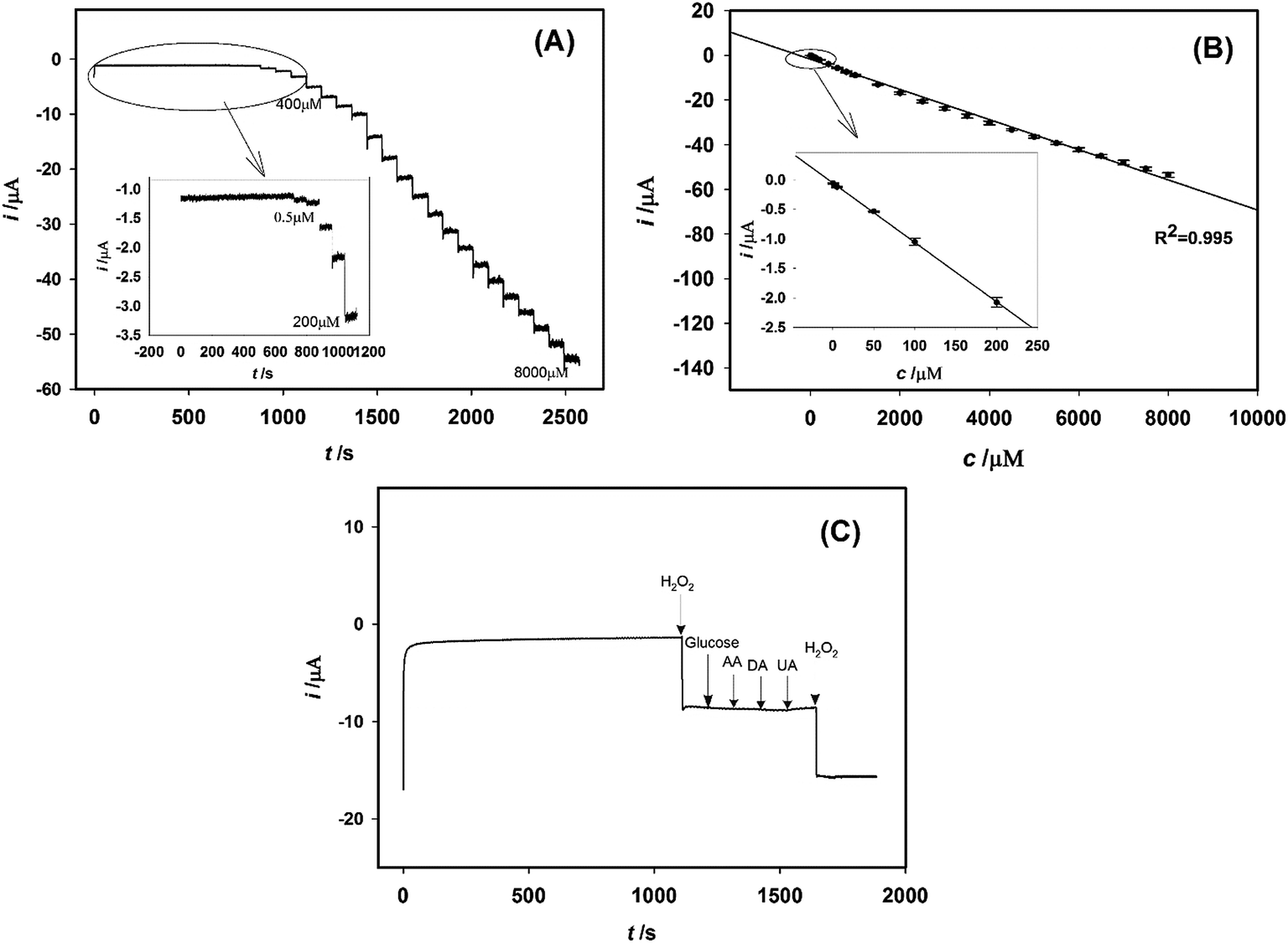 | ||
| Fig. 8 (A) Typical amperometric response of polystyrene@RGO–Pt modified GCE to the increasing concentration of H2O2 (0.5 μM–8000 μM) in PBS (pH 7.0). Applied potential: −0.05 V. (B) The current–concentration calibration curve (n = 5). (C) Amperometric response of polystyrene@RGO–Pt modified GCE to the sequential addition of 1 mM H2O2, 5.0 mM glucose, 0.1 mM ascorbic acid (AA), 0.1 mM dopamine (DA), 0.1 mM uric acid (UA), and 1 mM H2O2. Applied potential: −0.05 V. | ||
| Electrodes | Linear range | LOD | Ref. |
|---|---|---|---|
| Graphene–Pt nanocomposite | 2 μM–710 μM | 0.5 μM | 19 |
| Reduced graphene oxide decorated with high density Ag nanorods | 0.1 mM–70 mM | 2.04 μM | 58 |
| Graphene wrapped Cu2O nanocubes | 0.3 mM–7.8 mM | 20.8 μM | 60 |
| Three-dimensional graphene | 0.4 μM–660 μM | 80 nM | 61 |
| Nitrogen-doped graphene–silver nanodendrites | 100 μM to 80 mM | 0.26 μM | 59 |
| Carbon quantum dots/octahedral Cu2O nanocomposites | 5 μM to 5.3 mM | 2.8 μM | 62 |
| Graphene and gold nanorods nanocomposite | 30 μM to 5 mM | 10 μM | 63 |
| Polystyrene@RGO–Pt | 0.5 μM to 8 mM | 0.1 μM | This work |
3.4 Repeatability, stability, and selectivity
The repeatability of polystyrene@RGO–Pt modified GCE was evaluated by 7 successive determination of 1 mM H2O2 with the same electrode. It is found that the electrode exhibits a satisfying repeatability with a relative standard deviation (RSD) of 4.85%. After the polystyrene@RGO–Pt modified GCE was stored for 60 days at room temperature, it kept 89.2% of its initial current response. This long-term stability proved the better performance of the non-enzymatic polystyrene@RGO–Pt sensor than enzymatic sensors. The electrode-to-electrode reproducibility was also examined using five different electrodes. The RSD value was calculated to be 5.21%. The influence of some common electro-active substances, glucose, ascorbic acid (AA), dopamine (DA), and uric acid (UA), were assessed. Fig. 8C shows that 5.0 mM glucose, 0.1 mM AA, 0.1 mM dopamine (DA), and 0.1 mM UA did not cause obvious interference for the determination of 1.0 mM H2O2 (signal change below 5%). The selectivity of the proposed method may derive from the low overpotential for H2O2 reduction at polystyrene@RGO–Pt modified GCE.3.5 Determination of H2O2 in real samples
H2O2 in human serum sample were determined using polystyrene@RGO–Pt modified GCE. The protein in human serum was precipitated by trichloroacetic acid and centrifuged. The protein-free serum supernatant was used for analysis. The H2O2 levels were determined by amperometric method. The results are summarized in Table 2. The recoveries are between 102.0–104.2%. This result suggests the applicability of the non-enzymatic sensor.| Sample | Added (mM) | Found (mM) | Recovery (%) |
|---|---|---|---|
| 1 | 0.15 | 0.153 ± 0.002 | 102.0 |
| 2 | 0.30 | 0.311 ± 0.007 | 103.7 |
| 3 | 0.45 | 0.469 ± 0.009 | 104.2 |
4. Conclusions
This work provides a novel surfactant-free synthetic method of RGO and Pt nanocomposite. The strategy is promising for the fabrication of high performance non-enzymatic electrochemical sensors. The as prepared polystyrene@RGO–Pt microspheres modified electrode presents a high electrochemically active surface area that is 25 times of the geometric electrode surface area. Enhanced electrochemical performance of H2O2 reduction on polystyrene@RGO–Pt modified electrode was achieved due to large surface area and electrocatalytic activity of the nanocomposite. Amperometric method was constructed for the sensitive determination of H2O2. Moreover, the method was applied to the determination of H2O2 in human serum samples with satisfied results.Acknowledgements
This work was supported by Scientific Research Fund of Liaoning Provincial Education Department of China (No. L2014385), National Natural Science Foundation of China (No. 21375045), and Natural Science Foundation of Jilin Province (No. 20130101118JC).References
- C. Laloi, K. Apel and A. Danon, Curr. Opin. Plant Biol., 2004, 7, 323–328 CrossRef CAS PubMed.
- M. Giorgio, M. Trinei, E. Migliaccio and P. G. Pelicci, Nat. Rev. Mol. Cell Biol., 2007, 8, 722–728 CrossRef CAS PubMed.
- M. Liu, R. Liu and W. Chen, Biosens. Bioelectron., 2013, 45, 206–212 CrossRef CAS PubMed.
- W. Chen, B. Li, C. Xu and L. Wang, Biosens. Bioelectron., 2009, 24, 2534–2540 CrossRef CAS PubMed.
- J. Yuan, Y. Cen, X. J. Kong, S. Wu, C. L. Liu, R. Q. Yu and X. Chu, ACS Appl. Mater. Interfaces, 2015, 7, 10548–10555 CAS.
- P. F. Pang, Z. M. Yang, S. X. Xiao, J. L. Xie, Y. L. Zhang and Y. T. Gao, J. Electroanal. Chem., 2014, 727, 27–33 CrossRef CAS PubMed.
- X. Gao, L. Y. Jin, Q. Wu, Z. C. Chen and X. F. Lin, Electroanalysis, 2012, 24, 1771–1777 CAS.
- H. F. Tian, F. F. Liang, J. Jiao and J. B. Hu, J. Electrochem. Soc., 2013, 160, B125–B131 CrossRef CAS PubMed.
- C. C. Lu, M. Zhang, A. J. Li, X. W. He and X. B. Yin, Electroanalysis, 2011, 23, 2421–2428 CrossRef CAS PubMed.
- J. Zhou, C. Liao, L. Zhang, Q. Wang and Y. Tian, Anal. Chem., 2014, 86, 4395–4401 CrossRef CAS PubMed.
- P. Gao and D. Liu, RSC Adv., 2015, 5, 24625–24634 RSC.
- S. He, Z. Chen, Y. Yu and L. Shi, RSC Adv., 2014, 4, 45185–45190 RSC.
- I. S. Hosu, Q. Wang, A. Vasilescu, S. F. Peteu, V. Raditoiu, S. Railian, V. Zaitsev, K. Turcheniuk, Q. Wang, M. Li, R. Boukherroub and S. Szunerits, RSC Adv., 2015, 5, 1474–1484 RSC.
- K. C. Lin, T. H. Wu and S. M. Chen, RSC Adv., 2015, 5, 41224–41229 RSC.
- P. Ni, Y. Zhang, Y. Sun, Y. Shi, H. Dai, J. Hu and Z. Li, RSC Adv., 2013, 3, 15987–15992 RSC.
- Y. Peng, Z. Yan, Y. Wu and J. Di, RSC Adv., 2015, 5, 7854–7859 RSC.
- M. Sadhukhan, T. Bhowmik, M. K. Kundu and S. Barman, RSC Adv., 2014, 4, 4998–5005 RSC.
- E. Zor, M. E. Saglam, I. Akin, A. O. Saf, H. Bingol and M. Ersoz, RSC Adv., 2014, 4, 12457–12466 RSC.
- F. G. Xu, Y. J. Sun, Y. Zhang, Y. Shi, Z. W. Wen and Z. Li, Electrochem. Commun., 2011, 13, 1131–1134 CrossRef CAS PubMed.
- Y. J. Guo, S. J. Guo, J. Li, E. K. Wang and S. J. Dong, Talanta, 2011, 84, 60–64 CrossRef CAS PubMed.
- J. Li, S. J. Guo, Y. M. Zhai and E. K. Wang, Electrochem. Commun., 2009, 11, 1085–1088 CrossRef CAS PubMed.
- S. J. Guo, D. Wen, Y. M. Zhai, S. J. Dong and E. K. Wang, Biosens. Bioelectron., 2011, 26, 3475–3481 CrossRef CAS PubMed.
- C. Wu, D. Sun, Q. Li and K. B. Wu, Sens. Actuators, B, 2012, 168, 178–184 CrossRef CAS PubMed.
- W. Liu, C. Li, Y. Gu, L. Tang, Z. Zhang and M. Yang, Electroanalysis, 2013, 25, 2367–2376 CAS.
- W. Liu, J. Zhang, C. Li, L. Tang, Z. Zhang and M. Yang, Talanta, 2013, 104, 204–211 CrossRef CAS PubMed.
- N. Kitaori and S. Matsuishi, Mater. Technol., 2013, 31, 64–67 CAS.
- X. Li, X. Liu, W. Wang, L. Li and X. Lu, Biosens. Bioelectron., 2014, 59, 221–226 CrossRef CAS PubMed.
- J. Liu, L. Ruan, G. Xu, J. Lv and Y. Wu, Adv. Mater. Res., 2014, 873, 174–182 CrossRef.
- J. M. You, D. Kim and S. Jeon, Electrochim. Acta, 2012, 65, 288–293 CrossRef CAS PubMed.
- M. Giovanni, H. L. Poh, A. Ambrosi, G. J. Zhao, Z. Sofer, F. Sanek, B. Khezri, R. D. Webster and M. Pumera, Nanoscale, 2012, 4, 5002–5008 RSC.
- H. Feng, Y. Liu and J. Li, Chem. Commun., 2015, 51, 2418–2420 RSC.
- S. Zhang, Y. Shao, H. Liao, M. H. Engelhard, G. Yin and Y. Lin, ACS Nano, 2011, 5, 1785–1791 CrossRef CAS PubMed.
- Q. L. Zhang, T. Q. Xu, J. Wei, J. R. Chen, A. J. Wang and J. J. Feng, Electrochim. Acta, 2013, 112, 127–132 CrossRef CAS PubMed.
- S. Cao, L. Zhang, Y. Chai and R. Yuan, Talanta, 2013, 109, 167–172 CrossRef CAS PubMed.
- S. Mayavan, H. S. Jang, M. J. Lee, S. H. Choi and S. M. Choi, J. Mater. Chem. A, 2013, 1, 3489–3494 CAS.
- J. Zhang, Z. Chen, Z. Wang, W. Zhang and N. Ming, Mater. Lett., 2003, 57, 4466–4470 CrossRef CAS.
- W. S. Hummers, Jr and R. E. Offeman, J. Am. Chem. Soc., 1958, 80, 1339 CrossRef.
- C. Xu, X. Wang and J. W. Zhu, J. Phys. Chem. C, 2008, 112, 19841–19845 CAS.
- D. Li, M. B. Muller, S. Gilje, R. B. Kaner and G. G. Wallace, Nat. Nanotechnol., 2008, 3, 101–105 CrossRef CAS PubMed.
- S. Li, T. Qian, S. Wu and J. Shen, Chem. Commun., 2012, 48, 7997–7999 RSC.
- A. Grinou, Y. S. Yun and H. J. Jin, Macromol. Res., 2012, 20, 84–92 CrossRef CAS.
- N. Wu, X. L. She, D. J. Yang, X. F. Wu, F. B. Su and Y. F. Chen, J. Mater. Chem., 2012, 22, 17254–17261 RSC.
- W. L. Zhang, Y. D. Liu and H. J. Choi, J. Mater. Chem., 2011, 21, 6916–6921 RSC.
- S. Guo, D. Wen, Y. Zhai, S. Dong and E. Wang, ACS Nano, 2010, 4, 3959–3968 CrossRef CAS PubMed.
- A. Dutta and J. Ouyang, Appl. Catal., B, 2014, 158–159, 119–128 CrossRef CAS PubMed.
- J. Ding, B. Li, Y. Liu, X. Yan, S. Zeng, X. Zhang, L. Hou, Q. Cai and J. Zhang, J. Mater. Chem. A, 2015, 3, 832–839 CAS.
- F. Tuinstra and J. L. Koenig, J. Chem. Phys., 1970, 53, 1126–1130 CrossRef CAS PubMed.
- G. Wang, J. Yang, J. Park, X. Gou, B. Wang, H. Liu and J. Yao, J. Phys. Chem. C, 2008, 112, 8192–8195 CAS.
- S. Berciaud, S. Ryu, L. E. Brus and T. F. Heinz, Nano Lett., 2009, 9, 346–352 CrossRef CAS PubMed.
- B. P. Vinayan, R. Nagar, V. Raman, N. Rajalakshmi, K. S. Dhathathreyan and S. Ramaprabhu, J. Mater. Chem., 2012, 22, 9949–9956 RSC.
- S. Stankovich, D. A. Dikin, R. D. Piner, K. A. Kohlhaas, A. Kleinhammes, Y. Jia, Y. Wu, S. T. Nguyen and R. S. Ruoff, Carbon, 2007, 45, 1558–1565 CrossRef CAS PubMed.
- M. Lotya, P. J. King, U. Khan, S. de and J. N. Coleman, ACS Nano, 2010, 4, 3155–3162 CrossRef CAS PubMed.
- A. C. Ferrari, Solid State Commun., 2007, 143, 47–57 CrossRef CAS PubMed.
- J. Pu, S. Wan, Z. Lu, G.-a. Zhang, L. Wang, X. Zhang and Q. Xue, J. Mater. Chem. A, 2013, 1, 1254–1260 CAS.
- S. Fu, G. Fan, L. Yang and F. Li, Electrochim. Acta, 2015, 152, 146–154 CrossRef CAS PubMed.
- H.-C. Tao, X.-L. Yang, L.-L. Zhang and S.-B. Ni, J. Electroanal. Chem., 2015, 739, 36–42 CrossRef CAS PubMed.
- W. Chartarrayawadee, S. E. Moulton, D. Li, C. O. Too and G. G. Wallace, Electrochim. Acta, 2012, 60, 213–223 CrossRef CAS PubMed.
- B. Yu, J. C. Feng, S. Liu and T. Zhang, RSC Adv., 2013, 3, 14303–14307 RSC.
- M. T. Tajabadi, W. J. Basirun, F. Lorestani, R. Zakaria, S. Baradaran, Y. M. Amin, M. R. Mahmoudian, M. Rezayi and M. Sookhakian, Electrochim. Acta, 2015, 151, 126–133 CrossRef CAS PubMed.
- M. Liu, R. Liu and W. Chen, Biosens. Bioelectron., 2013, 45, 206–212 CrossRef CAS PubMed.
- F. N. Xi, D. J. Zhao, X. W. Wang and P. Chen, Electrochem. Commun., 2013, 26, 81–84 CrossRef CAS PubMed.
- Y. C. Li, Y. M. Zhong, Y. Y. Zhang, W. Weng and S. X. Li, Sens. Actuators, B, 2015, 206, 735–743 CrossRef CAS PubMed.
- P. Pang, Z. Yang, S. Xiao, J. Xie, Y. Zhang and Y. Gao, J. Electroanal. Chem., 2014, 727, 27–33 CrossRef CAS PubMed.
Footnote |
| † Electronic supplementary information (ESI) available. See DOI: 10.1039/c5ra11532a |
| This journal is © The Royal Society of Chemistry 2015 |