Phosphor-free InGaN micro-pyramid white light emitting diodes with multilayer graphene electrode
Binglei Fu†
a,
Yan Cheng†a,
Zhao Sia,
Tongbo Wei*a,
Xionghui Zengb,
Guodong Yuana,
Zhiqiang Liua,
Hongxi Lua,
Xiaoyan Yia,
Jinmin Lia and
Junxi Wanga
aState Key Laboratory of Solid-State Lighting, Institute of Semiconductors, Chinese Academy of Sciences, Beijing 100083, China. E-mail: tbwei@semi.ac.cn
bSuzhou Institute of Nano-tech and Nano-bionics, CAS, Ruoshui Road 398, Suzhou Industrial Park, Suzhou 215125, People's Republic of China
First published on 17th November 2015
Abstract
We reported the combination of micro-pyramid active layers and graphene electrode to realize the phosphor-free InGaN based white light emitting diodes (LEDs). SEM and TEM measurements were used to characterize the structural qualities of the micro pyramid arrays. According to CL and EDX analyses, the two emitting peaks originated from the indium segregation during the MOCVD process. Multilayer graphene was used to simplify the fabrication process for the electrical connection of the micro-pyramid arrays. The wavelength shift of two emitting peaks were both small with the increase of injection currents, indicating the weak QCSE. What was more, the reverse current leakage was also quite low for the phosphor-free InGaN micro-pyramid white light emitting diodes arrays connected by graphene.
Introduction
InGaN based light emitting diodes (LEDs) have shown great potential in solid state lighting systems as the band gap of InGaN can cover all visible light spectral regime.1,2 However, most state of the art white LEDs are made through the combination of blue LEDs and yellow phosphors which have many drawbacks such as the low light transfer efficiency.3,4 Phosphor-free white light emitting diodes utilizing the intrinsic band gap nature of InGaN material thus are highly desired and intensively studied.5–8 To achieve green and longer wavelength emission, the In content in InxGa1−xN quantum wells (QWs) should be higher than 20%. With the increase of In content in InGaN QWs, the lattice mismatch between the GaN and InGaN materials becomes more serious which leads to the In-phase separation and quantum-confined Stark effect (QCSE),9 both significantly deteriorate the LED efficiency. Many works have focused on with the QCSE issue, including the semi-/non-polar QWs,10 large overlap QWs,11,12 and ternary substrate method.13,14 The nanopatterned substrate were proved to be an useful method to achieve low dislocation density GaN epitaxy and thus enhance the LED efficiency.15–17 Even though tremendous progresses have been made, the quantum efficiency for QWs emitting at longer wavelength is still low.Several works published by the Nichia18 and GIST19 groups also showed the dual wavelength LED operation. Nichia's works depend on the following discoveries: QWs grown on different planes show different emission colors due to the variation of QW thickness and indium composition. People could easily control the emission color by changing the mask geometry with their method. However, their method needs the precise control of growth process to realize the designed micro-structure. What is more, the electrical connection of these micro-structures is also a problem. GIST groups' work avoids the problem of electrical connection. However, the etching process could cause serious damage to blue QWs. And the growth of high quality green QWs are also challenging.
Recently, the InGaN based micro- and nano- sized-pyramids have been seen as a promising candidate to achieve phosphor-free white LEDs.20–23 By growing InGaN layers on the semi- and non-polar facets of GaN pyramids could effectively reduce the QCSE and enhance the internal quantum efficiency.24,25 What is more, the In composition variation caused by In-phase separation could be controlled by the adoption of GaN pyramids, as the In composition highly depends on the position of hexagonal pyramids.26–28
Despite of these advantages, the wide application of InGaN based micro LEDs is hindered as it is difficult to realize electrically driven LEDs base on these microstructures. If the micro-sized pyramids is covered by p-type GaN layer completely, it would be too thick to obtain a uniformly flat p-GaN surface on this micrometer sized pyramids. On the other hand, if the space among different pyramids is filled with some kinds of fillings, such as polymethylmethacrylate (PMMA) and silicone gel, the fabrication process would be extremely complicated. Simple and low cost methods for electrical connection of micro LED structures thus are highly desired.
Graphene, due to its high transparency, incomparable thermal and electrical conductivity, flexibility and low cost, has been seen as a promising candidate for the next generation transparent electrodes. The application of multilayer graphene electrode on both lateral and vertical LEDs has been widely investigated.29,30 Recent studies have also shown that multilayer graphene transparent electrodes are highly suitable for the electrical connection of LEDs with micro structures such as nano-pillars and pyramids.31,32 In this work, the combination of micro-pyramid active layer arrays and graphene electrodes is introduced to achieve the electrically driven micrometer sized white light pyramids structure. The fabrication process is significantly simplified compared with traditional method due to the adoption of graphene on our micrometer sized pyramids structure, which may benefit much for the further application of these microstructures.
Experimental details
Synthesis of the InGaN micro-pyramid white LED arrays
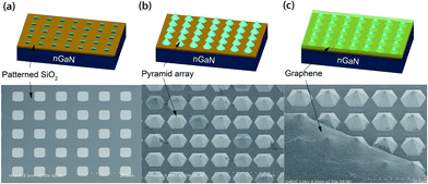
The sample was grown by Veeco P125 metal organic chemical vapor deposition (MOCVD) system on the c-plane sapphire substrates with thrimethylgallium (TMGa), thrimethylindum (TMIn), ammonia (NH3), biscyclopentadienylmagnesium (CP2Mg) and silane (SiH4) as gallium, indium, nitrogen, p-type and n-type dopant source, respectively. After the deposition of a low-temperature nucleation layer, the temperature was increased to 1050 °C to grow the Si-doped n-GaN layer. To realize the pyramidal structure, a mask of SiO2 was deposited on the c-plane n-GaN template. The holes were defined by the photolithographic mask. After a lift-off process, the mask shows openings of 5 μm × 5 μm with intervals of 5 μm which can be seen in Fig. 1(a). Then the n-GaN hexagonal pyramid was grown at 900 °C and 400 Torr for 15 min followed by the active region. The active region consisted of five periods of InGaN/GaN QWs. The QWs were grown at 730 °C while the barriers were grown at a higher temperature of 830 °C under 250 Torr. The TMIn and TEGa flux were 260 sccm and 30 sccm, respectively, and the respective growth times of the wells and barriers were 150 s and 180 s. After that, p-type layer were grown at 950 °C and 250 Torr, with a NH3 and TMGa flux of 6 L and 20 sccm, respectively. The pyramid LED arrays after the growth of p-GaN layer are presented in Fig. 1(b).Synthesis of multiple graphene film and the fabrication process of LED chips with graphene transparent electrodes
The multiple graphene layers used in this study were prepared by chemical vapour deposition (CVD) method in a mixture gases of methane and hydrogen at 1030 °C on copper foil. After the synthesis of graphene layers, the PMMA was spin coated onto the graphene/copper foil, and then the copper foil was etched in an aqueous iron chloride (FeCl3) solution. After the PMMA/graphene film were transferred onto the target substrates, the PMMA was removed by acetone.To achieve the LED chips (0.25 mm × 0.58 mm) with graphene transparent electrodes, the standard photolithography and inductive coupled plasma (ICP) etching was introduced to form the LED mesa. The micro-pyramid LED arrays were etched until the n-GaN layer was exposed. The thickness of the photoresist was 8 μm and the etching depth was 700 nm. After the formation of mesa structure, Cr/Pt/Au (70/40/1440 nm) was deposited by an e-beam evaporator, acting as metal electrodes. Then the pre-prepared multiple graphene film was transferred on the chip surface using the method we described above. Photolithography and O2 plasma were used to remove the graphene on the n-type electrode. All the pyramids on the mesa was interconnected by graphene film. The scanning electron microscope (SEM) images of pyramids interconnected with graphene can be found in Fig. 1(c).
The sheet resistance of the graphene is about 1000 ohm sq−1 and the transmittance is 95% in the visible light spectra range. The material quality of the multiple graphene films was characterized by Raman spectroscopy and could be found in our previous work.33
Results and discussions
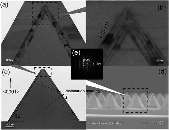
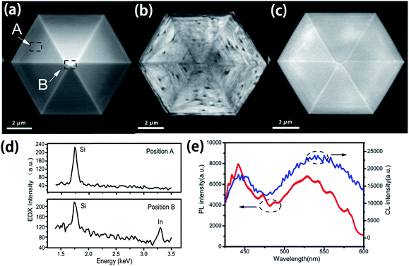
The structural quality of our micro-pyramid LED arrays is examined by SEM and transmission electron microscopy (TEM) and images could be found in Fig. 2. Fig. 2(d) shows the cross sectional SEM image of the micro-pyramid LED arrays. The LED arrays are regularly formed and patterned. The morphology of the pyramid shaped LED arrays is almost identical and nucleation on the SiO2 mask could be neglected, which reveals the uniformity of the growth process. Detailed structural analysis of the single LED pyramid is performed with TEM measurements. The structure of the whole pyramid is shown in Fig. 2(c). The SiO2 mask and opening of the mask are clearly resolved at the bottom of the pyramid. Most of the threading dislocations penetrating from the underlying n-GaN layers are blocked by the SiO2 mask. The dislocations located at the mask opening regions could extend into the pyramid structure. However, these dislocations are bent and extended vertical with the c-direction. This can be explained by the dislocation propagation resulting from the lateral overgrowth of inclined side planes which the dislocation intersects.34 As a result, the upper region of the pyramid structure is almost dislocation free as can be seen in Fig. 2(a). The n-type GaN consists of the most part of the pyramid arrays. The angle between inclined side walls and bottom plane of the pyramids is 62°, meaning that the inclined side plane is (10-11) plane. It has been reported that the width of QWs may be affected by the lateral overgrowth process on the micro-sized (11-22)22 and nano-sized (10-11)35 side walls. For QWs grown on GaN stripes with (11-22) side walls, the width of QWs would gradually increase from the base to the top of the stripes.20 Recent studies showed that for QWs grown on nano-sized GaN pyramid with (10-11) side walls, the thickness of QWs varies not only from the base to the top but from the surface to the inside of the pyramid.23,35 The variation of the width of QWs between different positions of GaN micro-structures might induce the monolayer white emitting characteristics. However, to our best knowledge, no QW width variation has been reported for QWs overgrown on the micro-sized (10-11) sidewalls. From Fig. 2(a) and (b), it is clear that the width of QWs grown on the (10-11) sidewalls of the micro-sized GaN pyramid are identical. The micro-sized (10-11) planes in wurtzite GaN are thermodynamically stable and thus the variation of QWs width is not obvious.26In order to investigate the emitting properties of the micro-size LED pyramids, the cathodoluminescence (CL) and photoluminescence (PL) measurement are performed and the spectra are shown in Fig. 3(e). Two separate emitting peaks could be resolved. One is located at 450 nm and another located at 550 nm. The spectra is very similar to that of white LEDs made through the combination of blue LED and yellow phosphors, indicating that the micro-sized pyramid LED arrays may be an ideal candidate to the phosphors-free white LEDs. The experiment parameters such as the growth temperature and width of QWs in our experiments would lead to a single emitting peak at about 460 nm (ref. 36) when the QWs were grown on traditional planar substrates. The two emitting band of our samples thus results from the overgrowth process on the n-GaN micro-pyramid with (10-11) sidewalls. Two mechanisms have been widely discussed as the origin of the yellow luminescence. One is the variation of the width of QWs as we discussed above. Another is the In segregation during the MOCVD process, which is resulted from the differences in the diffusion length of growth species.20 CL results shown in Fig. 3(b) and (c) indicated that the blue peak at 450 nm originates most from the bottom part of the six (10-11) planes, and the yellow emissions at 550 nm could be found at the whole pyramid structure and extremely strong at the six edges which are quite similar with the previous report.21 The energy-dispersive X-ray (EDX) spectra of position A and B shown in Fig. 3(a) is presented in Fig. 3(d), the peak of Si is taken as a reference. For position B, the In concentration is much higher as a result of the In segregation at the peak of micro-pyramids.
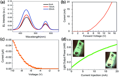
The electroluminescence of the chip is shown in Fig. 4(a). Two distinct emission peak are demonstrated at 440 nm and 565 nm, in conjunction with the CL and PL results. With the increasing current injection, there are no apparent shifts of the emission peaks, either blue band or yellow band. In planer LEDs, the blue shift of emitting band with longer wavelength is usually more severe as they suffer from more severe QCSE.37 As the QWs in our pyramid LED samples are grown on the semi-polar (10-11) planes, the effect of QCSE thus could be effectively eliminated. At the driving current of 20 mA, the working voltage is measured to be 15.21 V. This value is quite high compared with traditional planer LEDs with ITO transparent electrodes, which is mainly due to the large contact resistance between graphene and p-GaN and the high sheet resistance of graphene. In addition, rather than conventional flat structure, micro-pyramids are in direct contact with graphene. This may adversely affect the current injection and spreading capability of graphene. The contact problems thus need to be further investigated. Potential solutions dealing with the high turn on voltage of graphene electrode of LEDs includes the ITO quantum dots,38 metal sheets39 and NiO inserting layers40 between graphene and p-GaN. At the reverse voltage of 10 V, the leakage current of the chip is 0.05 μA, which is quite low. Such a low current reveals a relatively high reliability of the micro-pyramid white LEDs. The pyramids are successfully interconnected by graphene which guarantees a good reverse electrical characteristic of white LEDs. As is shown in Fig. 4(d), the light output powers (LOP) of the LED chip was 0.679 mW at 20 mA current injection. The emission images of the white LED chips at both 5 mA and 20 mA are shown in the inset. At 20 mA, the white light emit from all part of the chips, also indicated that the pyramids are successfully electrical connected. The CIE coordinates move from (0.368, 0.420) to (0.328, 0.399) as the current increases from 5 mA to 20 mA. Meanwhile, the color temperature increases from 4561 K to 5685 K, which essentially locates in the white region.
Conclusions
In conclusion, this paper reported a method with the combination of micro-sized pyramid active layers and graphene electrode to realize the phosphor free InGaN based white LEDs. The fabrication of micro-sized pyramid active layers is based on the traditional photolithography and the electrical connection of these pyramids is realized by introducing a multilayer graphene electrode, thus the fabrication process is significantly simplified. The pyramid LED arrays shows two separate EL peaks at about 440 nm and 565 nm, which resulted from the In segregation during the MOCVD process. The reverse leakage current is quite low, which reveals the high reliability of the micro-pyramid white LEDs with graphene electrodes.Acknowledgements
This work was supported by the National High Technology Program of China under Grant 2014AA032605 and 2013AA03A101, the National Natural Sciences Foundation of China under Grant 61274040, 61474109, and 61274008, 51202238, 51472229, and Youth Innovation Promotion Association, Chinese Academy of Sciences.Notes and references
- S. Pimputkar, J. S. Speck, S. P. DenBaars and S. Nakamura, Nat. Photonics, 2009, 3, 180 CrossRef CAS.
- M. H. Crawford, IEEE J. Sel. Top. Quantum Electron., 2009, 15, 1028 CrossRef CAS.
- N. Kimura, K. Sakuma, S. Hirafune, K. Asano, N. Hirosaki and R.-J. Xie, Appl. Phys. Lett., 2007, 90, 051109 CrossRef.
- E. F. Schubert and K. Kim, Science, 2005, 308, 1274 CrossRef CAS PubMed.
- M. Yamada, Y. Narukawa and T. Mukai, Jpn. J. Appl. Phys., 2002, 41, L246 CAS.
- G. Li, W. Wang, W. Yang and H. Wang, Surf. Sci. Rep., 2015, 70, 380 CrossRef CAS.
- I.-K. Park, J.-Y. Kim, M.-K. Kwon, C.-Y. Cho, J.-H. Lim and S.-J. Park, Appl. Phys. Lett., 2008, 92, 091110 CrossRef.
- T. Shioda, M. Sugiyama, Y. Shimogaki and Y. I. Nakano, Appl. Phys. Express, 2010, 3, 092104 CrossRef.
- H. S. Chen, D. M. Yeh, C. F. Lu, C. F. Huang, W. Y. Shiao, J. J. Huang, C. C. Yang, I. S. Liu and W. F. Su, IEEE Photonics Technol. Lett., 2006, 18, 1430 CrossRef CAS.
- D. F. Feezell, J. S. Speck, S. P. DenBaars and S. Nakamura, J. Disp. Technol., 2013, 9, 190 CrossRef CAS.
- A. Arif, Y. K. Ee and N. Tansu, Appl. Phys. Lett., 2007, 91, 091110 CrossRef.
- H. Zhao, G. Y. Liu, J. Zhang, J. D. Poplawsky, V. Dierolf and N. Tansu, Opt. Express, 2011, 19, A991 CrossRef CAS PubMed.
- J. Zhang and N. Tansu, J. Appl. Phys., 2011, 110, 113110 CrossRef.
- J. Zhang and N. Tansu, IEEE Photonics J., 2013, 5, 2600111 CrossRef.
- Y. K. Ee, X. H. Li, J. Biser, W. Cao, H. M. Chan, R. P. Vinci and N. Tansu, J. Cryst. Growth, 2010, 312, 1311 CrossRef CAS.
- Z. Lin, H. Yang, S. Zhou, H. Wang, X. Hong and G. Li, Cryst. Growth Des., 2012, 12, 2836 CAS.
- Y. Li, S. You, M. Zhu, L. Zhao, W. Hou, T. Detchprohm, Y. Taniguchi, N. Tamura, S. Tanaka and C. Wetzel, Appl. Phys. Lett., 2011, 98, 151102 CrossRef.
- M. Funato, K. Hayashi, M. Ueda, Y. Kawakami, Y. Narukawa and T. Mukai, Appl. Phys. Lett., 2008, 93, 021126 CrossRef.
- I. K. Park, J. Y. Kim, M. K. Kwon, C. Y. Cho, J. H. Lim and S. J. Park, Appl. Phys. Lett., 2008, 92, 091110 CrossRef.
- S. Srinivasan, M. Stevens, F. A. Ponce and T. Mukai, Appl. Phys. Lett., 2005, 87, 131911 CrossRef.
- Y.-H. Ko, J.-H. Kim, L.-H. Jin, S.-M. Ko, B.-J. Kwon, J. Kim, T. Kim and Y.-H. Cho, Adv. Mater., 2011, 23, 5364–5369 CrossRef CAS PubMed.
- J.-R. Chang, S.-P. Chang, Y.-J. Li, Y.-J. Cheng, K.-P. Sou, J.-K. Huang, H.-C. Kuo and C.-Y. Chang, Appl. Phys. Lett., 2012, 100, 261103 CrossRef.
- K. Wu, T. Wei, D. Lan, X. Wei, H. Zheng, Y. Chen, H. Lu, K. Huang, J. Wang, Y. Luo and J. Li, Appl. Phys. Lett., 2013, 103, 241107 CrossRef.
- S. C. Ling, T. C. Lu, S. P. Chang, J. R. Chen, H. C. Kuo and S. C. Wang, Appl. Phys. Lett., 2010, 96, 231101 CrossRef.
- R. M. Farrell, P. S. Hsu, D. A. Haeger, K. Fujito, S. P. DenBaars, J. S. Speck and S. Nakamura, Appl. Phys. Lett., 2010, 96, 231113 CrossRef.
- H. Yu, L. K. Lee, T. Jung and P. C. Ku, Appl. Phys. Lett., 2007, 90, 141906 CrossRef.
- S. Khatsevich, D. H. Rich, X. Zhang, W. Zhou and P. D. Dapkus, J. Appl. Phys., 2004, 95, 1832 CrossRef CAS.
- W. Feng, V. V. Kuryatkov, A. Chandolu, D. Y. Song, M. Pandikunta, S. A. Nikishin and M. Holtz, J. Appl. Phys., 2008, 104, 103530 CrossRef.
- Y. Zhang, L. Wang, X. Li, X. Yi, N. Zhang, J. Li, H. Zhu and G. Wang, J. Appl. Phys., 2012, 111, 114501 CrossRef.
- L. Wang, Y. Zhang, X. Li, Z. Liu, E. Guo, X. Yi, J. Wang, H. Zhu and G. Wang, Appl. Phys. Lett., 2012, 101, 061102 CrossRef.
- D.-W. Jeon, W. M. Choi, H.-J. Shin, S.-M. Yoon, J.-Y. Choi, L.-W. Jang and I.-H. Lee, J. Mater. Chem., 2011, 21, 17688 RSC.
- J. Kang, Z. Li, H. Li, Z. Liu, X. Li, X. Yi, P. Ma, H. Zhu and G. Wang, Appl. Phys. Express, 2013, 6, 072102 CrossRef.
- T. Tian, T. Zhan, J. Guo, J. Ma, Y. Cheng, Y. Zhao, X. Yi, Z. Liu and G. Wang, Appl. Phys. Express, 2015, 8, 042102 CrossRef.
- A. Sakai, H. Sunakawa and A. Usui, Appl. Phys. Lett., 1997, 71, 2259–2261 CrossRef CAS.
- K. Wu, T. Wei, H. Zheng, D. Lan, X. Wei, Q. Hu, H. Lu, J. Wang, Y. Luo and J. Li, J. Appl. Phys., 2014, 115, 123101 CrossRef.
- B. Fu, J. Kang, T. Wei, Z. Liu, Z. Liu, N. Liu, Z. Xiong, Z. Li, X. Wei, H. Lu, X. Yi, J. Li and J. Wang, Opt. Express, 2014, 22, A1284 CrossRef PubMed.
- V. C. Su, P. H. Chen, R. M. Lin, M. L. Lee, Y. H. You, C. I. Ho, Y. C. Chen, W. F. Chen and C. H. Kuan, Opt. Express, 2013, 21, 30065 CrossRef PubMed.
- T. H. Seo, K. J. Lee, T. S. Oh, Y. S. Lee, H. Jeong, A. H. Park, H. Kim, Y. R. Choi, E.-K. Suh, T. V. Cuong, V. H. Pham, J. S. Chung and E. J. Kim, Appl. Phys. Lett., 2011, 98, 251114 CrossRef.
- J. M. Lee, H. Y. Jeong, K. J. Choi and W. Park, Appl. Phys. Lett., 2011, 99, 041115 CrossRef.
- Y. Zhang, X. Li, L. Wang, X. Yi, D. Wu, H. Zhu and G. Wang, Nanoscale, 2012, 4, 5852 RSC.
Footnote |
| † Binglei Fu and Yan Cheng contributed equally to this work. |
| This journal is © The Royal Society of Chemistry 2015 |


