Synthesis of chitosan grafted-polyaniline/Co3O4 nanocube nanocomposites and their photocatalytic activity toward methylene blue dye degradation

Syed Shahabuddina, Norazilawati Muhamad Sarih*a, Fatem Hamime Ismaila, Muhammad Mehmood Shahidb and Nay Ming Huangb
aPolymer Research Laboratory, Chemistry Department, University of Malaya, Faculty of Science, 50603 Kuala Lumpur, Malaysia. E-mail: nmsarih@um.edu.my
bLow Dimensional Materials Research Centre, Physics Department, Faculty of Science, University of Malaya, 50603 Kuala Lumpur, Malaysia

Received 12th June 2015 , Accepted 22nd September 2015

First published on 22nd September 2015


Abstract

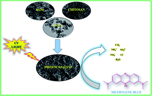
In the present investigation, chitosan-grafted-polyaniline copolymer (ChGP) and Co3O4 nanocube-doped ChGP nanocomposites have been successfully synthesised via oxidative-radical copolymerisation using ammonium persulfate in an acidic medium for the photocatalytic degradation of methylene blue dye. The prepared nanocomposites were characterised by field emission scanning electron microscopy (FESEM), transmission electron microscopy (TEM), thermogravimetric analysis (TGA), X-ray diffraction (XRD), UV-vis spectroscopy, X-ray photoelectron spectroscopy (XPS) and Fourier transform infrared spectroscopy (FTIR). FESEM and TEM images confirmed the formation of Co3O4 nanocubes and a crosslinked polymeric network. The photocatalytic activities of ChGP and Co3O4 nanocube-doped copolymers were evaluated by monitoring the degradation of methylene blue dye under UV illumination. The degradation efficiency of the copolymer photocatalysts that were doped with Co3O4 nanocubes was higher than that of the undoped copolymer. Furthermore, the nanocomposite with 2 wt% Co3O4 nanocubes with respect to aniline was an optimum photocatalyst, with an 88% degradation efficiency after 180 minutes of irradiation under UV light.

1. Introduction

Hazardous wastes and toxic water pollutants are the cause of serious environmental problems and have attracted considerable attention. The textile and food industries use organic dyes that cause environmental contamination because these dyes are non-biodegradable and highly toxic to aquatic creatures and have oncogenic effects on humans.1 3,7-Bis(dimethylamino)-phenothiazin-5-ium chloride, commonly known as methylene blue (MB), is a heterocyclic aromatic chemical compound that appears as an odourless, dark-green solid powder yielding a navy blue solution upon dissolution in water. MB is used commercially for various applications, such as textiles, papers, leathers, additives, laser printing, etc., and is an extremely noxious chemical that is primarily used as a dye.2,3 Among the wide variety of strategies to degrade hazardous waste materials, especially organic compounds, to less toxic or less harmful materials, photocatalysis has emerged as one of the most encouraging techniques because it epitomises a tranquil method of exploiting the energy of either natural sunlight or artificial illumination, such as ultraviolet light, microwaves, etc.4–7

In recent years, much scientific interest has been attracted towards the synthesis of conductive-polymer-based organic–inorganic hybrid nanocomposite materials. Conducting polymers, including polythiophene, polyacetylene, polypyrrole, polyphenylene and polyaniline, have been used extensively in multidisciplinary scientific research areas, including sensors,8–11 batteries,12,13 electronics, thermoelectric, electromagnetic, electro-luminescence, and electromechanical applications.14–18 Among these electrically conductive polymers, polyaniline (PANI) continues to fascinate researchers due to its distinctive electrochemical performance, environmental constancy, easy preparation and wide variety of applications.19–25 As a consequence, PANI has been studied comprehensively and has appeared as the most promising candidate for viable commercial applications. However, poor mechanical properties and poor solubility limit the use of PANI in many environmental applications.26 Chemical stability towards dopants, thermal stability, and good processability, along with electrical conductivity, in PANI can be achieved by integrating PANI into a flexible matrix.27,28 Due to its enhanced mechanical strength, biocompatibility, excellent adhesion and absorption ability, chitosan has gained significant attention in preparing semi-interpenetrating chitosan/polyaniline composites.29,30 Chitosan, which is obtained from the deacetylation of chitin, a natural biopolymer that is present in the exoskeleton of crustaceans, has an extensive array of applications in water treatment due to its non-toxicity and biodegradability.31,32 Due to the presence of hydroxyl (OH) and amine (NH2) functional groups, chitosan acts as a potential adsorbent that can bind to variety of chemical compounds through electrostatic attraction or hydrogen bonding. A wide variety of biopolymeric/conducting composite materials has been synthesised recently as adsorbent materials with potential environmental applications.33–35

Non-biodegradable dyes have been degraded photocatalytically using inorganic metal sulphide and metal oxides nanoparticles, such as ZnS,36 TiO2,37,38 ZnO,39 etc. Nanocomposites that are comprised of inorganic metal oxides and conducting polymers are potential photocatalysts that enhance the degradation rate of pollutants through synergetic effects between the metal oxide and the conducting polymer. PANI has been extensively used as conducting polymer, which acts as photo-sensitiser with a variety of inorganic metal oxides, such as TiO2. PANI has high electron mobility, and its electrons get easily excited under UV-visible light. As reported by Zhang et al., the electrons that are generated in the excited π× bonding orbital of the PANI molecule transfer into the conduction band of TiO2, where they react with oxygen and water molecules to form superoxide radicals and OH radicals, increasing the degradation potential of TiO2.40 The remarkable photochemical and electrochemical properties of spinel cobalt oxide (Co3O4) nanomaterials have attracted the attention of researchers because Co3O4 nanomaterials possess facile synthetic methodologies, excellent catalytic properties, and diverse morphologies.41 Co3O4 is a promising candidate for multiple applications, including fuel cells, lithium ion batteries, photocatalysis, artificial photosynthesis, gas sensors, etc., due to its wide abundance and economic cost.42–45

The present investigation focuses on the degradation of methylene blue (MB) dye using chitosan-grafted-polyaniline doped with Co3O4 nanocubes synthesised via in situ oxidative polymerisation. Co3O4 nanocubes were synthesised using the facile hydrothermal method and incorporated into the polymer matrix during polymerisation. The selection of chitosan-grafted-polyaniline for photocatalytic activity is based on high electron mobility and the easy excitement of electrons for PANI under UV illumination, along with the high adsorbent capacity of chitosan for MB due to electrostatic attraction or hydrogen bonding and the stabilising polymer composite. In addition, Co3O4 doping helps to generate electrons and holes in PANI to enhance the degradability of MB. The photocatalytic activity for the degradation of MB under UV-light irradiation was investigated spectrophotometrically with different wt% of Co3O4 contents, and the optimised Co3O4 content for high degradation performance was 2 wt% with respect to aniline, with enhanced photocatalytic activity. Facile synthesis, cost-effectiveness and higher photocatalytic degradation performance make these Co3O4 nanocube-doped chitosan-grafted-polyaniline nanocomposites potential photocatalysts for MB dye degradation.

2. Experimental section

2.1 Materials

Aniline (Fluka, ≥99%) was distilled under reduced pressure and stored in the dark before use. Ammonium peroxydisulfate, APS (Merck, ≥99%); cobalt acetate tetrahydrate (Sigma Aldrich, 99.8%); hydrochloric acid, HCl (Merck, 37%); methanol (Merck, 99.9%); and ammonia solution (R & M, 25%) were used as received without further purification. All of the reagents that were involved in the experiments were of analytical grade. Deionised water was used throughout the entire study.

2.2 Synthesis of Co3O4 nanocubes

A typical hydrothermal technique was utilised for the synthesis of cobalt oxide nanocubes. The calculated amount of Co(CH3COO)2·4H2O (83 mM) was dissolved in DI water under constant stirring to obtain a homogenous solution. To this solution, 15 ml of 6% ammonia solution was added dropwise at a rate of one drop per second with vigorous stirring. After two hour of stirring, 75 ml of the reaction mixture was transferred to a 100 ml Teflon-lined stainless steel autoclave and subjected to hydrothermal treatment at 180 °C for 12 h. The obtained precipitate of Co3O4 nanocubes were then washed thoroughly with DI water and ethanol several times and dried in a vacuum oven at 60 °C for 24 hours.

2.3 Preparation of polyaniline (PANI)

Polyaniline was synthesised by the oxidative polymerisation of distilled aniline that was dissolved in aqueous HCl (1 M), using ammonium persulfate (APS) as an oxidant. Aniline (0.0215 mol) was dissolved in 30 ml of an aqueous solution of HCl (1 M), and APS (0.0268 mol) was dissolved in 35 ml HCl (1 M). The oxidant solution was then added slowly to the aniline solution with continuous stirring at 25 °C. The reaction mixture was stirred continuously for two hours. The reaction mixture was then filtered and washed with HCl (0.5 M) until the filtrate became colourless and subsequently with DI water until the filtrate became neutral. The obtained polymer was dried in a vacuum oven at 60 °C overnight. The green colour of the obtained polymer indicated the formation of conductive polyaniline emeraldine salt.

2.4 Preparation of chitosan-grafted polyaniline (ChGP)

Chitosan-grafted polyaniline (ChGP) composite was synthesised as previously reported by Tiwari et al.46 Fig. S1 illustrates synthetic route for the preparation of the chitosan-grafted polyaniline copolymer. In a typical synthesis process, the required amount of chitosan was dissolved in 1% glacial acetic acid solution to make a 1 g L−1 concentration. To this solution, 1.5 × 10⁻² M aniline in 0.5 M HCl was added under continuous stirring at room temperature. After 30 minutes, 12.5 × 10⁻² M ammonium persulfate was added, and grafting was allowed to proceed for 2 hours. Subsequently, the solution was neutralised by 5% aqueous NaOH. The resulting ChGP was precipitated using absolute ethanol, filtered, washed with DI water until the filtrate became neutral and colourless, and dried in a vacuum oven. Finally, ChGP was ground to a fine powder, washed with acetone several times and dried at 50 °C in a vacuum oven for 72 hours.

2.5 Preparation of the ChGP–Co3O4 nanocomposite

Cobalt oxide nanocube-doped ChGP–Co3O4 nanocomposites were prepared with different wt% of Co3O4 (1, 2, and 4 wt% w.r.t. aniline). Co3O4 nanocubes were dispersed in DI water by sonication and added dropwise to aniline solution in HCl with vigorous stirring. The resulting mixture was sonicated for a few minutes until it became uniform. The work-up procedure was the same as described in the previous section. The obtained nanocomposites were labelled as ChGP, ChGPCo1, ChGPCo2, and ChGPCo4, indicating 0%, 1%, 2%, and 4% Co3O4 nanocubes, respectively.

2.6 Characterisation techniques

The surface morphological and elemental analysis of the synthesised product was conducted using a JEOL JSM-7600F field emission scanning electron microscope operated at 10 kV. The size and shape of the obtained Co3O4 nanocubes were studied using a JEOL JEM-2100F high-resolution transmission electron microscope. Thermal stability investigations were carried out using Perkin Elmer TGA6 under an N2 atmosphere at a heating rate of 10 °C min−1. Then, 10 mg of dried sample was loaded inside the alumina crucible, and the weight changes were monitored from 35 °C to 900 °C. X-ray diffraction (XRD) patterns were recorded using an Empyrean X-ray diffractometer from 2θ = 10° to 80° using Cu Kα radiations (λ = 1.5418 Å) at a scan rate of 0.02 s−1. X-ray photoelectron spectroscopy (XPS) was conducted using a Kratos analytical axis ultra-instrument with an Al Kα radiation source of 253.6 eV. Diffuse reflectance spectra were recorded with UV-vis spectrophotometer, Shimadzu model UV-2550 against BaSO4 white background. Fourier transform infrared (FT-IR) spectra of the powdered samples were recorded using a Perkin Elmer RX1 FT-IR ATR spectrometer in the range of 400–4000 cm−1 in spectral-grade KBr pellets.

2.7 Measurement of photocatalytic activities

The prepared samples were evaluated for photocatalytic activities by monitoring the degradation of methylene blue (MB) dye in the aqueous phase. In a typical experiment, 15 mg of the prepared nanocomposite powder was dispersed in 50 ml of an aqueous solution of MB with an initial concentration of 10 mg L−1. The adsorption–desorption equilibrium was achieved by stirring the mixture in a dark environment for 80 minutes. The photocatalytic degradation was then conducted by irradiating the above mixture using a UV lamp (CL-1000 UV Crosslinkers; 5 × 8 W) that was placed nearly 10 cm above the solution. To maintain the uniform dispersion of photocatalyst particles, the mixture was stirred continuously using a magnetic bar. Then, 3 ml of the dye suspension was withdrawn at a regular time interval and centrifuged. The UV-visible absorption spectra of the supernatant solution were analysed using a UV-visible spectrometer (Thermo Scientific Evolution) in 1 cm quartz cuvettes to monitor the characteristic absorption peak of MB.

3. Results and discussion

3.1 Morphological analysis of nanocomposites

FESEM images were obtained to characterise the morphologies of cobalt oxide nanocubes, PANI, chitosan and the nanocomposite containing 2 wt% cobalt oxide (ChGPCo2). The morphology of the cobalt oxide nanocubes is shown in Fig. 1(a) and (b) at different magnifications. From these images, it is evident that cube-shaped cobalt oxide nanoparticles were formed with an approximately uniform particle size. To further confirm the formation of cobalt oxide nanocubes, TEM images were taken (Fig. 1(g)) and clearly demonstrate the presence of cube-shaped particles in the nano range, confirming the formation of cobalt oxide nanocubes. Fig. 1(c) and (d) illustrate the morphologies of PANI and chitosan, where PANI showed a flake-like structure as the characteristic structure of PANI, whereas chitosan exhibited an irregular shape with a cotton-like accumulation. Fig. 1(e) represents ChGP composite material, clearly revealing the formation of cross-linked polymeric network with a high degree of porosity. This structure indicates the formation of a graft copolymer of chitosan and polyaniline, resulting in a highly porous material with cross-linked network. Fig. 1(f) shows the nanocomposite of chitosan-grafted polyaniline with 2 wt% cobalt oxide nanocubes (ChGPCo2) that are embedded in the polymer matrix.
image file: c5ra11237k-f1.tif
Fig. 1 FESEM micrographs of (a and b) Co3O4, (c) PANI, (d) chitosan, (e) ChGP (f) ChGPCo2 and (g) TEM image of Co3O4 nanocubes.

Because Co3O4 nanocubes were embedded in the polymeric matrix of the polymer, it was difficult to observe these cubes in the FESEM image of the nanocomposites, possibly due to their very low concentration (2 wt% w.r.t. aniline) as to the graft copolymer. Thus, an appropriate way to demonstrate the doping of cobalt oxide nanocubes in the polymeric matrix is FESEM-EDX and FESEM-mapping. Fig. 2 shows the mapping result of nanocomposite with 2% cobalt oxide nanocubes. It can be clearly seen from the result that cobalt oxide is uniformly present in the nanocomposite (Fig. 2(e)) along with carbon, nitrogen and oxygen. An elemental analysis (Fig. S2) shows the presence of cobalt, which further confirms the formation of cobalt oxide nanocube-doped chitosan-grafted polyaniline nanocomposites.


image file: c5ra11237k-f2.tif
Fig. 2 (a) FESEM image and (b) EDX elemental mapping of ChGPCo2 nanocomposite on a Si wafer for the following elements: (c) C, (d) N, (e) Co and (f) O.

3.2 Thermal analysis

Fig. 3 represents the TGA thermogram of cobalt oxide nanocubes, PANI, chitosan and chitosan-grafted polyaniline nanocomposites as performed under a nitrogen atmosphere by heating samples from 35 °C to 900 °C with a ramp rate of 10 °C min−1. As is evident from the graph, in Co3O4 the first weight loss is observed from 50–145 °C, which may be due to the dehydration of absorbed water. Co3O4 started to release oxygen as per the following equation:
Co3O4 → 3CoO + 1/2O2
and lost approximately 9% weight until 900 °C. Chitosan shows the major weight loss at 50 to 130 °C, 150 to 334 °C and 340 to 900 °C, which could be attributed to the loss of bound water, the decomposition of etheral groups and the decomposition of glucosamine residues, respectively. PANI shows three major weight losses from 40–120 °C, which may be due to the loss of adsorbed moisture, the decomposition of unreacted monomers and the decomposition of impurities; 130–260 °C is accredited to the loss of the dopant (HCl); and 260 to 900 °C is possibly due to the decomposition of hydrocarbon chains. It is evident from the graph that the thermal stability of ChGP, ChGPCo1, ChGPCo2 and ChGPCo4 improved compared to the thermal stabilities of chitosan and PANI. At the end of the experiment at 900 °C, 2.8% of ChGP, 3.0% of ChGPCo1, 5.9% of ChGPCo2, and 7.7% of ChGPCo4 persisted as residue. The thermal analysis data presented above proposed the following trend of stabilities: ChGPCo4 > ChGPCo2 > ChGPCo1 > ChGP, which can be accredited to the increase in the crosslinking of polymeric materials during grafting and to the presence of thermally stable pure Co3O4 at increased concentrations.

image file: c5ra11237k-f3.tif
Fig. 3 TGA thermogram analysis of PANI, chitosan, Co3O4 and nanocomposites.

3.3 XRD analysis

Fig. 4 and S3 show the typical XRD spectra of synthesised cobalt oxide nanocubes, PANI, chitosan and various chitosan-grafted polyaniline nanocomposites. As apparent by the XRD pattern of Co3O4 nanocubes, diffraction peaks appeared at the 2θ value of 31.34, 36.87, 44.84, 55.82, 59.36 and 65.28, which correspond to 220, 311, 400, 422, 511 and 440 planes of cubic Co3O4, respectively. These peaks are characteristic of Co3O4 and can be readily indexed as those of cubic structure fcc Co3O4 in accordance with JCPDS card no. 42-1467.47,48 For PANI, diffracted peaks appeared at 2θ = 15.5, 20.77, and 25.27, which are characteristic of PANI and indicate the polycrystalline structure of PANI.49 The peaks at angles of 2θ = 20.77 and 25.27 correspond to the periodic repetition of benzenoid and quinoid rings in PANI chains.50 Chitosan shows characteristic peaks at 2θ = 20.01, 26.64 and 40.5 due to the presence of hydroxyl and amine groups in the chitosan structure.51 The XRD spectra of chitosan-grafted polyaniline reveal a region of crystallinity from 2θ = 18–24, which suggests the grafting of PANI on a chitosan backbone.46 As evident from Fig. 6, when Co3O4 nanocubes are incorporated into the polymer matrix, the broad peaks of PANI and chitosan disappear, possibly due to the nanocubes acting as impurities that retard the growth of the PANI crystallite and chitosan-grafted polyaniline. The XRD patterns of PANI and chitosan-grafted polyaniline composites have a diffracted peak at approximately 2θ = 56 with d-spacing = 1.60 Å, which most likely originated from the divergent degree of protonation at all nitrogen atoms in emeraldine salt.52 Thus, the successful grafting of PANI onto chitosan and the formation of nanocomposites of Co3O4 and chitosan-grafted polyaniline have been established by XRD analysis.
image file: c5ra11237k-f4.tif
Fig. 4 XRD patterns of Co3O4, PANI and chitosan.

3.4 XPS analysis

X-ray photoelectron spectroscopy (XPS) analysis were employed for investigating the chemical nature of nanocomposite. Fig. 5(a) shows the survey spectra of ChGPCo2 illustrating the characteristic peaks of C, N, Cl, O and Co along with the Auger lines of Co(LMM), Co(LMV), O(KLL). The presence of chitosan in nanocomposite was confirmed by XPS spectra. Fig. 5(b) shows the high resolution C 1s core level spectra of ChGPCo2 which depicts three deconvoluted peaks at 284.77, 286.42 and 288.20 eV. The peak at 284.77 eV can be assigned to C–C bonding characteristic of polyaniline and chitosan.53 The peak at 286.42 eV can be assigned to C–N, C–O or C–O–C bonding that belongs to chitosan. The third peak at 288.20 eV may be assigned to C[double bond, length as m-dash]O or C–O–C bonding characteristic of chitosan54 as it usually contains some acetamido groups that come from the original chitin. As shown in Fig. 5(c), the Co 2p core level spectrum for ChGPCo2 nanocomposites shows two peaks at 779.85 and 781.68 eV which are attributed to the Co 2p1 and Co 2p3 respectively. Hence XPS studies clearly reveal the formation of the Co3O4 doped graft copolymer of chitosan and PANI.
image file: c5ra11237k-f5.tif
Fig. 5 XP spectra of ChGPCo2 (a) survey scan. The symbol * represents the Auger peaks; for Co(LMV), Co(LMM) and O(KLL) (b) C 1s core level and (c) Co 2p core level.

3.5 UV-vis analysis

Fig. S4 represents the UV-visible spectra of chitosan, Co3O4, PANI and ChGPCo2 respectively. As evident from Fig. S4(a) chitosan gives a flat absorption spectra, showing no peaks in the range of 350–800 nm which is a characteristic of chitosan. Fig. S2(b) represents typical absorption spectrum of Co3O4 nanocubes where two distinct broad absorption bands in the range of 400 to 550 and 600 to 750 nm are observed which can be assigned to the O2− → Co2+ and O2− → Co3+ charge transfer process respectively.55 PANI shows two absorption bands in the range of 420 to 470 and 500 to 750 nm which are typical of the protonated form of PANI. The first absorption band can be assigned to the π–π* transition of benzenoid rings, while second band can be assigned to the π–π* transition of quinoid rings on the PANI chains. ChGPCo2 has optical absorption in the entire visible light region 400–800 nm as shown by its featureless diffuse spectrum. As ChGPCo2 exhibits absorption in the whole visible region, it is certain that it could function as effective light absorber and worthy photocatalysts. The band gap (Eg) of Co3O4 and PANI was further determined by using Perkin Elmer method of measuring the band gap energy.56 The band gap of Co3O4 was calculated to be 1.6 eV which is close to the theoretical value of bulk Co3O4 (1.77 eV). The band gap value for PANI was found to be 2.77 eV which is in well agreement with theoretical value of 2.8 eV.

3.6 FTIR analysis

The FTIR spectra of cobalt oxide nanocubes, chitosan, PANI and chitosan-grafted polyaniline composite are shown in Fig. 6. The IR bands at 1560 cm−1 and 1480 cm−1 represent the characteristic C–C stretching of quinoid and benzenoid rings in PANI, respectively. The peak at 1297 cm−1 could be attributed to C–N and C[double bond, length as m-dash]N stretching in PANI. The broad IR bands at 3400–3436 cm−1 can be attributed to the stretching mode of –OH and the primary amine group in chitosan. The IR peak at 1652 cm−1 corresponds to the C[double bond, length as m-dash]O stretching in the amide groups of chitosan. The peaks at 2920–2877 cm−1 represent aliphatic –CH stretching vibrations. Two peaks at 667 cm−1 and 574 cm−1 in the spectrum of cobalt oxide are the characteristic peaks that confirm the spinel structure of Co3O4. FTIR spectra of ChGPCo2 comprise peaks of chitosan and PANI. As a result of the overlapping of the –OH stretching of chitosan and the N–H stretching of PANI in graft copolymers, the IR band at approximately 3400 cm−1 became less intense and broad. These reduced intensities indicate that a considerable amount of O–H at chitosan has been grafted with polyaniline chains.57 Peaks around 2920–2852 cm−1 can be attributed to N–H stretching with hydrogen-bonded amine groups and free –OH stretching. Peaks around 1514–1417 cm−1 are due to the quinoid and benzenoid stretching of PANI. IR peaks at 807 cm−1 and 1127 cm−1 were allocated to out-of-plane C–H bending and in-plane C–H bending. The characteristic peaks at 667 and 574 cm−1 in Co3O4 were detected at 647 and 559 cm−1 in Co3O4-doped chitosan-grafted-polyaniline nanocomposites. The intensity of the peaks significantly enhances with an increased dopant concentration. This slight shifting of the band towards red could be attributed to some amount of weak van der Waals attraction between the polymer chain and Co3O4. Hence, the FTIR studies clearly indicate the formation of a graft copolymer of polyaniline on the chitosan backbone with some interaction between PANI and Co3O4.
image file: c5ra11237k-f6.tif
Fig. 6 FTIR spectrum of Co3O4, PANI, chitosan and ChGPCo2.

3.7 Photocatalytic degradation of MB under UV illumination

The photocatalytic aqueous-phase degradation of MB in the presence of chitosan, ChGP and Co3O4 nanocube-doped nanocomposites was investigated under UV-light illumination at ambient temperature. The adsorption of MB on the surface of the catalyst under dark conditions was monitored for 80 minutes via UV-vis absorption spectra as illustrated in Fig. 7(a) in order to attain adsorption–desorption equilibrium. It is apparent from Fig. 7(a) that the adsorption of MB molecules on the surface of the catalyst increased with time, and within 20 minutes, most of the catalyst surface was saturated with MB. After attaining equilibrium, approximately 9%, 12.5%, 18.4%, 19.8%, and 17.4% of MB was adsorbed on the surface of chitosans ChGP, ChGPCo1, ChGPCo2 and ChGPCo4, respectively. The adsorption of MB increases gradually after the grafting of PANI onto chitosan, and this adsorption is further enhanced by doping with Co3O4 nanocubes, possibly due to some molecular interaction of nanoparticles with MB. As the percentage of Co3O4 increased from 2 wt% (w.r.t. aniline) to 4 wt%, there was a slight decrease in adsorption that could be caused by the reduction in the active surface area of catalyst due to the agglomeration of nanocubes at a high doping percentage.
image file: c5ra11237k-f7.tif
Fig. 7 (a) Adsorption–desorption equilibrium rate of MB under dark conditions versus time in the presence of various photocatalysts (b) photodegradation rate of MB at different time intervals in the presence of various photocatalysts.

As seen from Fig. 7(b), chitosan and ChGP have low photocatalytic activities compared to the photocatalytic activities of ChGPCo1, ChGPCo2 and ChGPCo4. Fig. 8(a) illustrates the percentage decomposition of MB at different intervals of time, signifying the following degradation trend: ChGPCo2 > ChGPCo4 > ChGPCo1 > ChGP > chitosan. Fig. 8(b) depicts the UV-vis adsorption spectra of the ChGPCo2 nanocomposite irradiated under UV illumination for different time intervals. As evident from the figure, the decrease in the intensities of the adsorption band with the increasing irradiation time clearly indicates the efficient degradation of MB by a photocatalytic phenomenon. Nearly 88% of MB degraded within an interval of 180 minutes, predicting an enhanced photocatalytic activity of ChGPCo2 nanocomposite over chitosan, ChGP, ChGPCo1 and ChGPCo4, where the decompositions were approximately 23%, 27%, 54% and 65%, respectively. In the case of chitosan, the degradation is nearly 23% after 180 minutes, which could be due to the self-decomposition of MB because under UV light, MB can be self-decomposed to an extent of approximately 20% in a period of 2 hours.58 The extent of decomposition increases to 27% upon the grafting of PANI onto a chitosan backbone, which indicates some amount of photocatalytic phenomenon in ChGP due to the conducting chains of PANI. With nanocomposites doped by Co3O4, the degradation was enhanced from ChGPCo1 to ChGPCo2 and decreased from ChGPCo2 to ChGPCo4. Thus, 2 wt% Co3O4 nanocubes (w.r.t. aniline) was predicted to be an optimum photocatalyst composition.


image file: c5ra11237k-f8.tif
Fig. 8 (a) Percentage degradation of MB in the presence of various photocatalysts (b) UV-vis absorption spectra of MB aqueous solution at different times in the presence of ChGPCo2 as a photocatalyst.

MB itself can decompose in UV light to a certain extent by absorbing energy from UV irradiations forming singlet and triplet species. These singlets and triplets that are produced by MB molecules are extremely energetic and active, which immediately react with the available oxygen to form advanced oxidation species (AOS) comprising superoxide, peroxide and hydroxyl radicals. These AOS are responsible for the degradation and mineralisation of MB. The possible mechanism of degradation of MB is illustrated in Fig. S5. This decomposition, however, is insignificant because it can only degrade a very small percentage of MB in the absence of any photocatalyst. Chitosan is a biopolymer that has a tendency to form strong interactions with organic molecules through hydrogen bond formation due to the presence of amine and hydroxyl groups in its chain. This property of chitosan can be exploited to enhance the adsorption of MB on the surface of a catalyst, which is a prime requisition of efficient catalysis. Chitosan by itself does not enhance the degradation of MB under UV light but augments the adsorption of dye onto the surface of the catalyst. Chitosan-grafted PANI and its nanocomposites with Co3O4 nanocubes are capable of generating AOS under UV irradiation, leading to the degradation of MB. PANI in its conductive emeraldine salt form exhibits enhanced electron mobility, and these electrons can be excited by photoillumination. The electrons that are present in HOMO of PANI adsorb the energy from UV light and jump to LUMO through π–π× transitions, which are the characteristic transitions of PANI. These transitions in PANI are responsible for the generation of electrons and holes in the conduction band (LUMO) and valence band (HOMO) of PANI molecules, respectively, thereby leading to the formation of AOS and degradation of MB. Very few electron–hole pairs generated in PANI molecules migrate on the surface to initiate the series of photochemical reactions, while most of them recombine rapidly, thus reducing the efficiency of PANI to be used as an efficient photocatalyst alone. To enhance the photocatalytic efficiency of chitosan-grafted polyaniline, semiconducting Co3O4 nanocubes were incorporated into the graft copolymer during the polymerisation process. In Co3O4 nanocube-doped nanocomposites, the d-orbital conducting band of Co3O4 undergoes chemical bond interaction with LUMO of PANI upon UV irradiation. Due to these electronic interactions, the LUMO of PANI came close to the d-orbital conducting band of Co3O4, and electrons were injected from the conduction band of Co3O4 to LUMO of PANI. Thus, the electrons that were injected into the LUMO of PANI reached the surface and reacted with O2 to form peroxides and superoxide radicals. The corresponding holes that were generated in the valence band of PANI and Co3O4 react with H2O to form hydroxyl radicals, which again degrade MB as per Fig. S5. Thus, Co3O4 enhances the charge separation in PANI to facilitate the formation of AOS, whereas chitosan aids in the adsorption of MB on the surface of the catalyst, thereby increasing the overall efficiency of the photocatalyst. Scheme 1 provides the schematic illustration of the possible mechanism of MB degradation in the presence of Co3O4-doped nanocomposites.


image file: c5ra11237k-s1.tif
Scheme 1 Schematic illustration for the formation of advanced oxidation species in Co3O4-doped chitosan-grafted-polyaniline hybrid photocatalyst.

3.8 Comparison of photocatalytic efficiencies

Table 1 shows the comparison of photocatalytic efficiencies of the present catalyst with those of others reported in literature. The prepared catalyst at an initial dye concentration of 10 mg L−1 with irradiation time of 180 minutes showed the photodecomposition efficiency of 88%. In earlier studies for the degradation of MB, Zhang et al.59 reported 88% degradation, Wang et al.60 reported 81.74% degradation, Kuo et al.4 reported 67% degradation, Soltani et al.6 reported 73% degradation, Autin et al.38 reported 88% degradation, Dai et al.7 reported 87% degradation, Subramanian et al.58 reported 76.58% degradation with different time of irradiation as shown in Table 1. In a very recent work Xia et al.61 have reported 95% photodecomposition of MB. In this perspective, it is well established that our catalyst render enhanced efficiency.
Table 1 Comparison of photocatalytic efficiencies
Catalyst Dye degraded % degradation Degradation time (min) Reference
PANI sensitized TiO2 Methylene blue 88 300 59
PANI–TiO2 Methylene blue 81.74 120 60
N2 modified TiO2 Methylene blue 67 240 4
Zn/CdS Methylene blue 73 360 6
TiO2 Methylene blue 88 120 38
AgBr/ZnO Methylene blue 87 240 7
PANI–TiO2 Methylene blue 76.58 120 58
FeOOH-LDO Methylene blue 95 180 61
Chitosan-grafted-PANI/Co3O4 Methylene blue 88 180 This work


3.9 Reproducibility of the photocatalysts

Fig. 9 shows the reproducibility of ChGPCo2 as photocatalyst for MB degradation. The photocatalyst after first cycle was recovered by centrifugation and filtration followed by thorough washing with DI water, dried at 80C in vacuum oven for two hours and subsequently employed as photocatalyst for second and third cycle in order to examine their photocatalytic efficiencies. ChGPCo2, ChGPCo2–R1 and ChGPCo2–R2 (where R represents repeatedly used catalyst) denotes the photocatalyst for first, second and third cycle which shows the marginal decrease in their photocatalytic efficiencies with each repeated cycle. Table 2 represents the photocatalytic efficiencies of photocatalyst which shows that the efficiency of the catalyst decreases in second and third run. This decrease in efficiency may be due to the fact that a considerable amount of unavoidable weight loss occurred during recovery and purification of photocatalyst. This weight loss contribute to the decrease in photocatalytic efficiency of catalyst in each repeated cycle.58 Moreover the decrease in photocatalytic activity can also be attributed to the adsorption of degradation by-products on the active sites of photocatalyst surface thereby decreasing the number of available photoactive sites.62
image file: c5ra11237k-f9.tif
Fig. 9 Reproducibility of ChGPCo2 (the symbol D represent dark adsorption whereas R represents repeated cycle).
Table 2 Percent of MB dye dark adsorption and photodecomposition
Catalyst % of dark adsorption % of photodecomposition
ChGPCo2 19.80% 88%
ChGPCo2–R1 16% 79.6%
ChGCo2–R2 14.88% 66.16%


4 Conclusions

Chitosan-grafted-polyaniline and Co3O4 nanocube-doped nanocomposites have been successfully synthesised through an in situ oxidative polymerisation technique. Co3O4 nanocubes were successfully incorporated into the cross-linked network of the polymeric matrix. The present investigation highlights the synergistic effect of the conducting copolymer and the semiconducting metal oxide, which leads to the enhancement of the photocatalytic efficiency of the nanocomposite. The synthesised polymeric nanocomposite exhibits greater photocatalytic activity and degrades MB efficiently within a short duration of time. The synthetic methodology proposed here can be used to synthesise Co3O4 nanocomposites with other conducting polymers, which may address the present-day issue of environmental pollution.

Acknowledgements

The authors would like to thank the University of Malaya (UM) for the research facilities and financial support through HIR/MOHE/SC/F00031 and Postgraduate Research Fund, PPP (PG141-2014B).

References

  1. J. McCann and B. N. Ames, Proc. Natl. Acad. Sci. U. S. A., 1976, 73, 950–954 CrossRef CAS.
  2. V. Adams, J. Marley and C. McCarroll, Br. Dent. J., 2007, 203, 585–587 CrossRef CAS PubMed.
  3. A. J. Linz, R. K. Greenham and L. F. Fallon Jr, J. Occup. Environ. Med., 2006, 48, 523–528 CrossRef CAS PubMed.
  4. Y.-L. Kuo, T.-L. Su, F.-C. Kung and T.-J. Wu, J. Hazard. Mater., 2011, 190, 938–944 CrossRef CAS PubMed.
  5. U. Riaz, S. Ashraf and M. Aqib, Arabian J. Chem., 2014, 7, 79–86 CrossRef CAS PubMed.
  6. N. Soltani, E. Saion, M. Z. Hussein, M. Erfani, A. Abedini, G. Bahmanrokh, M. Navasery and P. Vaziri, Int. J. Mol. Sci., 2012, 13, 12242–12258 CrossRef CAS PubMed.
  7. K. Dai, J. Lv, L. Lu, Q. Liu, G. Zhu and D. Li, Mater. Lett., 2014, 130, 5–8 CrossRef CAS PubMed.
  8. S. Sukeerthi and A. Contractor, Indian J. Chem., Sect. A: Inorg., Bio-inorg., Phys., Theor. Anal. Chem., 1994, 35, 565–571 Search PubMed.
  9. K. Ogura, T. Saino, M. Nakayama and H. Shiigi, J. Mater. Chem., 1997, 7, 2363–2366 RSC.
  10. K. Ogura, H. Shiigi, M. Nakayama and A. Fujii, J. Electrochem. Soc., 1998, 145, 3351–3357 CrossRef CAS PubMed.
  11. R. Patil, S. Ahmed, H. Shiigi, M. Nakayama and K. Ogura, J. Polym. Sci., Part A: Polym. Chem., 1999, 37, 4596–4604 CrossRef CAS.
  12. A. MacDiarmid, L. Yang, W. Huang and B. Humphrey, Synth. Met., 1987, 18, 393–398 CrossRef CAS.
  13. M. Mizumoto, M. Namba, S. Nishimura, H. Miyadera, M. Koseki and Y. Kobayashi, Synth. Met., 1989, 28, 639–646 CrossRef.
  14. J. Unsworth, B. Lunn, P. Innis, Z. Jin, A. Kaynak and N. Booth, J. Intell. Mater. Syst. Struct., 1992, 3, 380–395 CrossRef PubMed.
  15. K. Schoch, IEEE Electr. Insul. Mag., 1994, 10, 29–32 CrossRef.
  16. M. Angelopoulos, IBM J. Res. Dev., 2001, 45, 57–75 CrossRef CAS.
  17. N. Gospodinova and L. Terlemezyan, Prog. Polym. Sci., 1998, 23, 1443–1484 CrossRef CAS.
  18. S. Bhadra, D. Khastgir, N. K. Singha and J. H. Lee, Prog. Polym. Sci., 2009, 34, 783–810 CrossRef CAS PubMed.
  19. A. Heeger, P. Smith, J. L. Brédas and R. Silbey, Conjugated Polymers: The Novel Science and Technology of Highly Conducting and Non-linear Optically Active Materials, Kluwer Academic Publishers, Dordrecht The Nederlands, 1991 Search PubMed.
  20. E. Genies, A. Boyle, M. Lapkowski and C. Tsintavis, Synth. Met., 1990, 36, 139–182 CrossRef CAS.
  21. A. G. MacDiarmid and A. J. Epstein, Faraday Discuss. Chem. Soc., 1989, 88, 317–332 RSC.
  22. F. Lux, Polymer, 1994, 35, 2915–2936 CrossRef CAS.
  23. J. Kong, N. R. Franklin, C. Zhou, M. G. Chapline, S. Peng, K. Cho and H. Dai, Science, 2000, 287, 622–625 CrossRef CAS.
  24. C. R. Martin, Nanomaterials-A Membrane-based Synthetic Approach, DTIC Document, 1994 Search PubMed.
  25. J. Huang, S. Virji, B. H. Weiller and R. B. Kaner, J. Am. Chem. Soc., 2003, 125, 314–315 CrossRef CAS PubMed.
  26. A. Tiwari, J. Macromol. Sci., Part A: Pure Appl. Chem., 2007, 44, 735–745 CrossRef CAS PubMed.
  27. X. Lu, C. Y. Tan, J. Xu and C. He, Synth. Met., 2003, 138, 429–440 CrossRef CAS.
  28. K. Takahashi, K. Nakamura, T. Yamaguchi, T. Komura, S. Ito, R. Aizawa and K. Murata, Synth. Met., 2002, 128, 27–33 CrossRef CAS.
  29. C. Peniche, W. Argüelles-Monal, N. Davidenko, R. Sastre, A. Gallardo and J. San Román, Biomaterials, 1999, 20, 1869–1878 CrossRef CAS.
  30. S. R. Shin, S. J. Park, S. G. Yoon, G. M. Spinks, S. I. Kim and S. J. Kim, Synth. Met., 2005, 154, 213–216 CrossRef CAS PubMed.
  31. G. Kousalya, M. Rajiv Gandhi and S. Meenakshi, Adsorpt. Sci. Technol., 2010, 28, 49–64 CrossRef CAS.
  32. M. R. Gandhi and S. Meenakshi, Carbohydr. Polym., 2013, 91, 631–637 CrossRef PubMed.
  33. S. Hena, J. Hazard. Mater., 2010, 181, 474–479 CrossRef CAS PubMed.
  34. A. G. Yavuz, E. Dincturk-Atalay, A. Uygun, F. Gode and E. Aslan, Desalination, 2011, 279, 325–331 CrossRef CAS PubMed.
  35. X. Liu, W. Zhou, X. Qian, J. Shen and X. An, Carbohydr. Polym., 2013, 92, 659–661 CrossRef CAS PubMed.
  36. A. M. Golsheikh, H. N. Lim, R. Zakaria and N. M. Huang, RSC Adv., 2015, 5, 12726–12735 RSC.
  37. S. S. Ray and M. Biswas, Synth. Met., 2000, 108, 231–236 CrossRef CAS.
  38. O. Autin, C. Romelot, L. Rust, J. Hart, P. Jarvis, J. MacAdam, S. A. Parsons and B. Jefferson, Chemosphere, 2013, 92, 745–751 CrossRef CAS PubMed.
  39. D. P. Singh, Sci. Adv. Mater., 2010, 2, 245–272 CrossRef CAS PubMed.
  40. L. Zhang, P. Liu and Z. Su, Polym. Degrad. Stab., 2006, 91, 2213–2219 CrossRef CAS PubMed.
  41. F. Jiao and H. Frei, Energy Environ. Sci., 2010, 3, 1018–1027 CAS.
  42. L. Hu, Q. Peng and Y. Li, J. Am. Chem. Soc., 2008, 130, 16136–16137 CrossRef CAS PubMed.
  43. M. M. Shahid, A. Pandikumar, A. M. Golsheikh, N. M. Huang and H. N. Lim, RSC Adv., 2014, 4, 62793–62801 RSC.
  44. F. Jiao and H. Frei, Angew. Chem., Int. Ed., 2009, 48, 1841–1844 CrossRef CAS PubMed.
  45. W.-Y. Li, L.-N. Xu and J. Chen, Adv. Funct. Mater., 2005, 15, 851–857 CrossRef CAS PubMed.
  46. A. Tiwari and V. Singh, eXPRESS Polym. Lett., 2007, 1, 308–317 CrossRef CAS.
  47. Z.-S. Wu, W. Ren, L. Wen, L. Gao, J. Zhao, Z. Chen, G. Zhou, F. Li and H.-M. Cheng, ACS Nano, 2010, 4, 3187–3194 CrossRef CAS PubMed.
  48. Z. Song, Y. Zhang, W. Liu, S. Zhang, G. Liu, H. Chen and J. Qiu, Electrochim. Acta, 2013, 112, 120–126 CrossRef CAS PubMed.
  49. A. Rahy and D. J. Yang, Mater. Lett., 2008, 62, 4311–4314 CrossRef CAS PubMed.
  50. L. Shi, X. Wang, L. Lu, X. Yang and X. Wu, Synth. Met., 2009, 159, 2525–2529 CrossRef CAS PubMed.
  51. L. Yu, Y. He, L. Bin and F. Yue'e, J. Appl. Polym. Sci., 2003, 90, 2855–2860 CrossRef PubMed.
  52. X. Zong, K. Kim, D. Fang, S. Ran, B. S. Hsiao and B. Chu, Polymer, 2002, 43, 4403–4412 CrossRef CAS.
  53. M. Aldissi and S. Armes, Macromolecules, 1992, 25, 2963–2968 CrossRef CAS.
  54. L. Dambies, C. Guimon, S. Yiacoumi and E. Guibal, Colloids Surf., A, 2001, 177, 203–214 CrossRef CAS.
  55. T. He, D. Chen, X. Jiao, Y. Wang and Y. Duan, Chem. Mater., 2005, 17, 4023–4030 CrossRef CAS.
  56. J. Dharma, Simple Method of Measuring the Band Gap Energy Value of TiO2 in the Powder Form using a UV/Vis/NIR Spectrometer, http://www.perkinelmer.com/CMSResources/Images/44-74327APP_UVVISNIRMeasureBandGapEnergyValue.pdf, (accessed August 2015) Search PubMed.
  57. S. H. Hosseini, J. Simiari and B. Farhadpour, Iran. Polym. J., 2009, 18, 3–13 CAS.
  58. E. Subramanian, S. Subbulakshmi and C. Murugan, Mater. Res. Bull., 2014, 51, 128–135 CrossRef CAS PubMed.
  59. H. Zhang, R. Zong, J. Zhao and Y. Zhu, Energy Environ. Sci., 2008, 42, 3803–3807 CAS.
  60. F. Wang, S. Min, Y. Han and L. Feng, Superlattices Microstruct., 2010, 48, 170–180 CrossRef CAS PubMed.
  61. S. Xia, L. Zhang, G. Pan, P. Qian and Z. Ni, Phys. Chem. Chem. Phys., 2015, 17, 5345–5351 RSC.
  62. C. G. Silva, W. Wang and J. L. Faria, J. Photochem. Photobiol., A, 2006, 181, 314–324 CrossRef CAS PubMed.

Footnote

Electronic supplementary information (ESI) available. See DOI: 10.1039/c5ra11237k

This journal is © The Royal Society of Chemistry 2015
Click here to see how this site uses Cookies. View our privacy policy here.