DOI:
10.1039/C5RA11136F
(Paper)
RSC Adv., 2015,
5, 86179-86190
Catalytic application of SO42−/Fe–ZrO2 nanoparticles synthesized by a urea hydrolysis method for environmentally benign one pot synthesis of 1,8-dioxodecahydroacridines
Received
11th June 2015
, Accepted 6th October 2015
First published on 6th October 2015
Abstract
A series of Fe2O3–ZrO2 mixed oxides (FexZr) were prepared by a colloidal precipitation method using urea as a mild hydrolyzing agent. The sulfate ions were grafted onto the surface of the mixed oxide by treatment with dilute sulfuric acid and subsequent thermal activation. The resulting sulfate grafted mixed oxides (SFexZr) were characterized using XRD, FTIR, Raman, surface area measurement, UV-vis, XPS, TPD, SEM, FESEM and HRTEM techniques. XRD study indicated formation of a substitutional type solid solution in a limited composition range due to incorporation of iron ions into the zirconia lattice. The selective stabilization of the tetragonal phase of zirconia was observed in the mixed oxide system. The microstructural properties of the sulfate grafted mixed oxide were obtained from the Fourier analysis of the broadened XRD profiles. The presence of well dispersed iron oxide species in the zirconia lattice was ascertained from the Raman and UV-vis study. XPS and FTIR studies confirmed the presence of grafted sulfate functional groups. HRTEM analysis of the SFe10Zr sample revealed the presence of well dispersed mixed oxide particles with sizes in the range of 10–30 nm. The catalytic activity of the SFexZr material was evaluated for the synthesis of 1,8-dioxo-decahydroacridines by multicomponent condensation of dimedone, substituted aryl aldehydes and substituted anilines. A variety of dioxodecahydroacridine molecules were obtained with high yield and purity. The SFe10Zr material exhibited high surface area, and excellent catalytic activity for the synthesis of the 1,8-dioxo-decahydroacridine molecules.
1. Introduction
Application of thermally robust, structurally stable and recyclable heterogeneous catalytic systems for value added chemical synthesis is a promising field of research with potential application in pharmaceutical and related fine chemical industries.1–3 Sulfated metal oxides are a promising class of heterogeneous catalytic materials which have been extensively investigated in recent years for their application in industrial catalysis.4–6 Among the sulfated metal oxides, sulfated zirconia (SZ) is the most widely investigated heterogeneous catalytic material. In recent years, novel synthetic methods have been developed to prepare sulfated zirconia (SZ) nanoparticles with enhanced surface area, porosity and sulfate retention capacity.7,8 Mesoporous sulfated zirconia with uniform pore size distribution and good thermal stability have also been prepared using ionic liquids, sodium dodecyl sulfate and CTAB as a structure directing agent.5,9,10 Composite materials such as SZ–SBA-15, SZ–MWCNT, and SZ–KIL-2, containing finely dispersed SZ particles have also been synthesized and their catalytic properties have been evaluated.6,11,12 The surface area, phase stability, sulfur retention capacity as well as catalytic activity of SZ can be improved significantly by doping transition metal and lanthanide ions into zirconia structure. Doping of zirconia with Al, Fe, Si and Mn ions stabilizes the tetragonal phase, prevent agglomeration of the particles and improves the uptake of sulfate ions.13–18 Nagaraju and Shamshuddin have synthesized a series of Fe and Mn co-doped sulfated zirconia catalyst. A significant enhancement of the surface area and acidity has been observed due to the doping of these transition metal ions.18 The incorporation of lanthanide ions such as La3+, Ce4+ into the sulfated zirconia lattice generate materials with enhanced catalytic activity and selectivity.19–21 For example, the incorporation of the lanthanide ions enhances the selectivity for isomerization product during n-hexane isomerization by reducing the number of strong acidic sites on the catalyst surface.21 The transition and lanthanide metal doped sulfated zirconia materials have been used as catalyst for esterification of levulinic acid, Meerwin–Ponndorf–Verley reductions, selective catalytic reduction of NOx, isomerization reactions, vapor phase pinacol rearrangement, synthesis of 3-picoline, biodiesel production, dihydropyridine synthesis, iodination of arenes and Michael addition reactions.13–21 Although there are many investigations on the catalytic activity of sulfated metal oxides, their applicability towards synthesis of biologically important molecules is yet to be explored fully. In the present investigation, we have synthesized a series of sulfate grafted Fe2O3–ZrO2 mixed oxides nanomaterials employing urea as a mild hydrolyzing agent and studied their catalytic application for synthesis of structurally diverse 1,8-dioxo-decahydroacridine molecules.
Acridine and their derivatives represent an important class of nitrogen containing heterocyclic compounds which exhibit potential pharmacological properties and utility in industrial technologies.22–25 Acridine compounds have been studied as bioactive agents because of their antimalarial, antiprotozoal, antibacterial and antileishmanial properties.22–26 Acridine derivatives including 9-phenyl acridines, exhibit anticancer activities by inducing apoptosis in human cancer cell lines.25 In addition to their important pharmacological properties, acridine analogues are used as dyes, fluorescent materials for visualization of biomolecules, and in laser technology because of their useful spectroscopic properties.22,25 In view of the broad utility of acridine derivatives, the synthesis of this class of compounds under mild reaction conditions is of paramount importance in synthetic organic chemistry. The acid catalyzed multicomponent condensation of aromatic aldehydes, anilines and dimedone by heating in organic solvents or under microwave irradiation has recently emerged as a potential route for synthesis of structurally diverse 1,8-dioxo-decahydroacridine molecules.27 Very few catalytic methods are available in literature which deals with the synthesis of 1,8-dioxo-decahydroacridine molecules via MCR route. The catalyst system which have been studied for this three component condensation include p-dodecylbenzenesulfonic acid (DBSA) [Hmim]TFA, Amberlyst-15, FSG-Hf(NPf2)4, ceric ammonium nitrate, Fe3O4 nanoparticles and iodine impregnated silica particles.27 Many of the reported procedure utilize supported reagents or homogeneous catalysts which suffer from drawbacks such as catalyst handling and recyclability, laborious work-up procedures, and harsh reaction conditions. The heterogeneous catalytic protocols although overcome these disadvantages, the reaction require longer time and moderate yield of the products are obtained. Therefore, the development of simple, efficient, high-yielding and environment friendly methods using structurally stable and recyclable heterogeneous catalysts is highly desirable. In this work, we have reported the application of SFexZr nanomaterials as heterogeneous catalyst for synthesis of structurally diverse 1,8-dioxo-decahydroacridine under environmentally benign conditions.
2. Materials and methods
2.1. Preparation of the Fe2O3 (x mol%)–ZrO2 mixed oxides (FexZr)
The FexZr mixed oxides were prepared by co-hydrolysis and condensation of iron nitrate (Fe(NO3)2·9H2O) and zirconyl chloride (ZrOCl2·8H2O) salt solution using urea as a mild base. In a typical preparation procedure, required amount of 0.5 M iron nitrate and zirconyl chloride precursor salt solutions were mixed with equimolar quantity of urea solution. The mixed solution was then refluxed for 12 h at 100 °C. The resulting colloidal aqueous suspension was filtered and washed repeatedly with hot distilled water (until Cl− free). The obtained solid material was dried in a hot air oven at 120 °C for 12 h and calcined at 500 °C for 2 h to obtain the FexZr composite material. Using this procedure FexZr material with iron oxide content of 5, 10, 15 and 20 mol% was synthesized.
2.2. Preparation of sulfated Fe2O3 (x mol%)–ZrO2 mixed oxides (SFexZr)
4 g of FexZr material was dispersed in 200 ml of 0.5 M sulfuric acid and stirred for 24 h at room temperature. The colloidal suspension was filtered, washed with 0.05 M H2SO4, dried overnight at 120 °C and then calcined at 500 °C for 2 h to generate the SFexZr materials.
2.3. Characterization of the SFexZr materials
The X-ray diffraction patterns of the SFexZr materials were obtained using a Rigaku Ultima IV multipurpose X-ray diffraction system. The XRD measurements were carried out in the 2θ range of 20–70° with a scan speed of 2 degrees per minute using Bragg–Brantano configuration. The FTIR spectra of different composite oxide samples (as KBr pellets) were obtained in transmittance mode by using Perkin-Elmer infrared spectrometer with a resolution of 4 cm−1 in the range of 400 cm−1 to 4000 cm−1. The UV-vis absorbance spectra of the sample were recorded using Shimadzu spectrometer model 2450 with BaSO4 coated integration sphere in the range of 200–800 nm. The specific surface areas of the samples were determined by BET method using N2 adsorption/desorption at 77 K on a Quantachrome autosorb gas sorption system. The composite oxide samples were degassed at 150 °C for 2 h prior to the sorptometric studies. The SEM image of the SFexZr samples was recorded using a JEOL JSM-6480 LV microscope (acceleration voltage 15 kV). FESEM study of the SFe10Zr sample was performed by using Nova NanoSEM/FEI microscope. Prior to FESEM analysis the powder sample was placed on carbon tape followed by gold sputtering for three minutes. The micro-Raman spectra were obtained on a Horiba Jobin-Yvon spectrometer using a 17 mW He–Ne laser light source (excitation wavelength 632.8 nm). The TEM images of the SFe10Zr material was recorded using JEM-2100 HRTEM equipment using carbon coated copper grids as substrate. The X-ray photoelectron spectra of SFe10Zr sample was recorded using SPECS make (Germany) spectrophotometer with 150 mm hemispherical analyzer at band pass energy of 12 eV. Monochromatic Al Kα radiation of 1486.74 eV was used as X-ray source. Binding energy corrections due to electrostatic charging was made using the Zr 3d peak (182.2 eV), assuming ZrO2 to be the major species. The number of acidic sites on the SFexZr material was estimated by ammonia TPD experiments using a Micromeritics AutoChem II 2920 chemisorption apparatus equipped with a TCD detector. Prior to ammonia adsorption, 500 mg sample was preheated at 120 °C under flowing He for 30 min, followed by heating under He environment at 450 °C for 1 h, then cooled to 120 °C. Subsequently, the sample was exposed to flowing ammonia gas mixture (5% NH3 in He) for 1 h, and then purged by He gas for 30 min to remove excess physisorbed ammonia. The NH3-TPD profiles were recorded by ramping the temperature from 373 to 723 K at a rate of 10 K min−1. The 1H NMR spectra were recorded with Bruker 400 MHz NMR spectrometer using TMS as internal standard.
2.4. Catalytic activity study for synthesis of 1,8-dioxodecahydroacridines
The catalytic activity of the SFexZr material was evaluated for the synthesis of 1,8-dioxodecahydroacridines by multicomponent condensation of dimedone, aryl aldehydes and substituted anilines. In a typical synthesis procedure, dimedone (2 mmol), benzaldehyde (1 mmol) and aniline (1 mmol) and 50 mg of SFe10Zr catalyst in 5 ml of acetonitrile was refluxed for 150 minutes. The progress of the reaction was monitored using TLC. After completion of the reaction, the catalyst particles were filtered from the acetonitrile solution. The reaction products were recovered from the acetonitrile solution and recrystallized using ethanol as solvent to afford 9,10-diphenyl-3,3,6,6-tetramethyl-10-phenyl-3,4,6,7,9,10-hexahydro-2H,5H-acridine-1,8-dione as the sole product with 80.5% yield (Table 2, entry 1). The catalyst particles were washed three times with 10 ml portion of ethyl acetate and calcined at 450 °C for 2 h to regenerate the catalyst. All the 1,8-dioxodecahydroacridines molecules synthesized in this work are reported compounds, which are identified by comparison of their spectral and physical characteristics with literature.26
3. Results and discussion
3.1. Characterization of the SFexZr materials
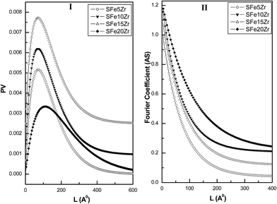
The XRD patterns of the ZrO2, Fe2O3 along with FexZr materials are presented in Fig. 1. The zirconia material synthesized by urea hydrolysis method exhibit characteristic XRD peaks corresponding to a mixture of monoclinic and tetragonal zirconia phases (Fig. 1a) (JCPDS-ICDD file no. 83-0940 and 81-1545). The percentage tetragonal phase present in the ZrO2 sample is calculated to be 60% as per the Toroya's method.28 Upon incorporation of Fe2O3 into the ZrO2 lattice, the tetragonal phase of zirconia is selectively stabilized. No separate crystalline phase corresponding to Fe2O3 is detected up to 10 mol% Fe2O3 content in the mixed oxide (Fig. 1a–c). However for sample containing 15 and 20 mol% Fe2O3 the characteristic XRD peaks corresponding to the hematite phase are observed (Fig. 1d and e) (JCPDS-ICDD file no. 72-0469). The XRD patterns of the SFexZr materials are presented in Fig. 2. Grafting of sulfate species over zirconia surface is beneficial in terms of increase in tetragonal phase content (Fig. 2a). The SZ material contains 71% tetragonal phases. All the SFexZr materials exhibit characteristic reflections from the tetragonal phase (Fig. 2b–e). The stabilization of the tetragonal phase of zirconia for SFexZr materials can be ascribed mainly to two factors. The substitution of the Fe3+ introduces oxygen vacancy in the zirconia lattice which helps in preventing the tetragonal to monoclinic phase transformation.29 The other factor which can contribute to the tetragonal phase stabilization is the reduction in grain boundary area due to the presence of sulfate ions. It has been reported that the sulfate ions preferentially segregate along the grain boundary region of sulfated zirconia catalyst.30 The presence of sulfate ions along grain boundary prevents the motion of dislocations across adjacent grains, which is responsible for the tetragonal to monoclinic phase transition. Another important observation from the XRD study is the shift of the tetragonal (111) towards the higher 2θ value upto 10 mol% iron oxide content (Fig. 3I). For SFe15Zr and SFe20Zr the shift in the peak position is also observed, however, it is less pronounced. This observation suggests the formation of a substitutional type solid solution in a limited composition range due to Fe3+ ion substitution in ZrO2 lattice. The formation of such substitutional solid solution has been observed in earlier studies.29,31 The substitution of the Zr4+ ions (ionic radius 0.79 Å) by Fe3+ ions (ionic radius 0.65 Å) lead to slight lattice contraction which is manifested in the shift of the (111) peak to higher 2θ value (Fig. 3II). The XRD study clearly indicate that upto 10 mol% Fe2O3 content, the SFexZr material contain a substitutional solid solution phase of the type  whereas for SFe15Zr and SFe20Zr materials a mixture of solid solution and hematite phase exist in the sulfate grafted samples. The crystallite sizes and rms stains for the SFexZr samples are calculated from the Fourier line profile analysis of the XRD patterns by Warren and Averbach method using software BRAEDTH.32,33 The Fourier line profile analysis is carried out by taking the ZrO2 T (111) and T (220) peaks for all composite oxide samples. The plot of distribution function (PV), and size coefficient (AS) as function of the Fourier length (L) for the SFexZr samples are presented in Fig. 4 panel I and II, respectively. The SFe5Zr and SFe10Zr materials exhibit narrow distribution functions, the distribution being confined upto Fourier length of 30 nm (Fig. 4I). This observation indicates that these materials contain a major fraction of the crystallites with size less than 30 nm. In contrast to this observation, the SFe15Zr and SFe20Zr materials show wide distribution function indicating presence of polycrystalline particles with larger average crystallite size. Fig. 5 represents a plot of the crystallite size and rms strain plotted against the iron content in the SFexZr materials. The SFexZr material exhibits average crystallite sizes in the range of 10–30 nm. The crystallite size of the mixed oxide materials increases with iron oxide content. The calculated rms strain exhibit an inverse correlation with the crystallite size. The higher strain observed for SFe5Zr and SFe10Zr materials can be ascribed to different types of random and local lattice distortion in zirconia nanocrystallites.
 |
| | Fig. 1 X-ray diffraction patterns of (a) ZrO2, (b) Fe5Zr, (c) Fe10Zr, (d) Fe15Zr, (e) Fe20Zr and (f) Fe2O3. | |
 |
| | Fig. 2 X-ray diffraction patterns of (a) SZ, (b) SFe5Zr, (c) SFe10Zr, (d) SFe15Zr, (e) SFe20Zr and (f) SFe. | |
 |
| | Fig. 3 XRD patterns indicating shift in (111) peak to higher 2θ value for tetragonal zirconia phase with iron oxide content (a) SZ, (b) SFe5Zr, (c) SFe10Zr, (d) SFe15Zr and (e) SFe20Zr (I) and (II) Vegard's plot. | |
 |
| | Fig. 4 Fourier line profile analysis plots for SFexZr samples. | |
 |
| | Fig. 5 Variation of the crystallite size and lattice strain with iron content for the SFexZr materials. | |
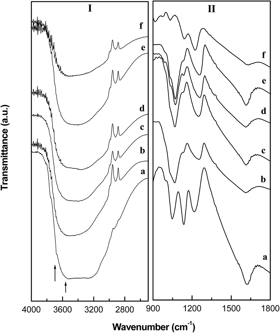
The FTIR spectra of the SFexZr materials are presented in Fig. 6. In the stretching frequency region of the IR spectrum (Panel 6I), the sulfate grafted materials show a broad and intense IR band ranging between 3700–3200 cm−1. This band occurs due to the O–H vibration of lattice hydroxyl groups and coordinated water present on the surface of FexZr materials.34 The broadness of the peak indicates existence of a variety of –OH species differing in bond strength. Another factor which can contribute to the broadness of the band is the hydrogen bonding between physisorbed water molecules and the surface hydroxyl and sulfate groups. In the bending mode region, an intense broad band is observed around 1620 cm−1 (Panel II). This band arises due to the bending vibration of –OH group originating from the structural hydroxyls.34 In addition, four vibrational bands are observed at 985, 1044, 1135 and 1215 cm−1 which are ascribed to the S–O and S![[double bond, length as m-dash]](https://www.rsc.org/images/entities/char_e001.gif) O vibrations of bidentate sulfate species attached to the mixed oxide surface.35 The IR study confirmed the presence of grafted sulfate species with water molecules in its coordination environment. The water present in the hydration sphere of the sulfate group has been described as a source of Brønsted acidity in case of SZ catalysts.4
O vibrations of bidentate sulfate species attached to the mixed oxide surface.35 The IR study confirmed the presence of grafted sulfate species with water molecules in its coordination environment. The water present in the hydration sphere of the sulfate group has been described as a source of Brønsted acidity in case of SZ catalysts.4
 |
| | Fig. 6 FTIR spectra of (a) SZ, (b) SFe5Zr, (c) SFe10Zr, (d) SFe15Zr, (e) SFe20Zr and (f) SFe. | |
The presence of the surface sulfate species is further confirmed from the XPS analysis of the SFe10Zr sample. The XPS spectra of SFe10Zr material is presented in Fig. 7. The survey spectra in Fig. 7a, exhibit all the characteristic spectral features corresponding to the Zr, Fe, O and S species. Moreover, no impurity species are observed in the survey spectra except the adventitious carbon. In the zirconium 3d spectral region, the SFe10Zr material exhibit a doublet centered at 182.2 eV (3d5/2) with a spin orbit splitting of 2.4 eV (Fig. 7b). This observed binding energy is consistent with the Zr(IV) sites of the sulfated zirconia catalyst.36–38 In the high resolution Fe 2p spectrum, two distinct peaks are noticed at 710.9 eV (2p3/2) and 724.3 eV (2p1/2) along with a shake-up satellite peak at 719.3 eV. These peaks are characteristics of Fe3+ ions in oxide environment.39–41 In the S 2p region, a broad and low intense peak is observed at 169.3 eV (Fig. 7d). This peak corresponds to the S6+ species present in sulfate environment.36,37 The O 1s spectrum is broad and asymmetric in nature. This spectrum upon deconvolution yields a low energy peak at 530.3 eV corresponding to the oxide anions from the Fe10Zr composite oxide. Pure ZrO2 and Fe2O3 exhibit O 1s peak at 530.4 eV and 530.0 eV, respectively.36,41 The assignment of the 530.3 eV peak to oxide oxygen is in agreement with literature reported value.38–40 The high binding energy feature at 532.0 eV in the O 1s spectra can be assigned to the oxygen from the surface grafted sulfate species.37–39 The XPS study clearly revealed the presence of grafted sulfate species on the surface of the Fe10Zr composite oxide.
 |
| | Fig. 7 XPS spectra of SFe10Zr material. | |
The Raman spectra of the SFexZr materials synthesized using urea hydrolysis method is presented in Fig. 8. The Raman technique is a powerful tool for microstructural analysis of crystalline oxide phases through observation of their phonon modes. Particularly, Raman technique is effective for characterization of hematite nanostructures in composite oxides.42–44 In the present study, the SFe5Zr material exhibit Raman bands at 152, 273, 322, 460, and 642 cm−1 due to the tetragonal phase of zirconia (Fig. 8a).45 The vibrational feature characteristic to the α-Fe2O3 phase is absent for the SFe5Zr sample. This observation indicates that the iron oxide is present in a highly dispersed state in the zirconia lattice without formation of separate crystalline hematite phase. For SFe10Zr sample, in addition to the characteristic tetragonal zirconia vibrations, new broad and asymmetric vibrational bands are observed at 229, 296 and 609 cm−1 in the Raman spectrum (Fig. 8b). These bands occur due to transition from the A1g and Eg modes of hematite phase.42,43 The intensity of these bands increases with iron oxide content. Simultaneously, a decrease in intensity of Raman band of tetragonal ZrO2 phase is observed in Fig. 8b–d. Hematite belongs to the D63d space group and exhibit seven phonon lines (two A1g and five Eg modes).42 For SFe20Zr and SFe material all phonon lines of α-Fe2O3 phase are observed in the Raman spectrum (Fig. 7d). Another notable feature from the Raman study is the blue shift (∼5–10 cm−1) of the hematite phonon lines of SFe10Zr materials compared to SFe15Zr, SFe20Zr and SFe materials. The blue shift can be ascribed to the to the phonon confinement effect.46 The distinctive feature of the spectra of SFe15Zr and SFe20Zr materials is the appearance of a broad Raman band at 655 cm−1 (Fig. 8c and d). This band has been observed earlier for hematite films (50 nm thickness) as well as iron oxide nanoparticles embedded in silica matrix and has been assigned to Raman forbidden, IR active longitudinal optical (LO) Eu mode of hematite.44 This mode is believed to be activated due to the disorder in the α-Fe2O3 lattice. The Raman study of the SFexZr composite materials clearly indicate that the iron oxide phase remain in a well dispersed state in the zirconia lattice upto 10 mol% Fe2O3 content, whereas at higher loading nanocrystalline hematite phase with structural disorder exist in the composite oxide.
 |
| | Fig. 8 Raman spectra of (a) SFe5Zr, (b) SFe10Zr, (c) SFe15Zr, (d) SFe20Zr and (e) SFe. | |
The UV-vis spectra of the SFexZr mixed oxide materials along with pure SZ and SFe materials are presented in Fig. 9. Sulfate zirconia prepared by urea hydrolysis method show a sharp absorption band at 225 nm (Fig. 9a). This band is assigned to the O2− → Zr4+ charge transfer transition arising out of the host zirconia lattice.31 Incorporation of the iron oxide species into the zirconia lattice significantly changes the absorption feature of zirconia (Fig. 9b–e). The Fe3+ ions are known to exhibit two charge transfer transitions (t1 → t2 and t1 → e).47–49 The energy of these transitions is strongly dependent on the coordination atmosphere of the Fe3+ ions. For iron oxide species three distinct absorption regions have been observed in the literature.47–49 Isolated Fe3+ ions in octahedral coordination shows absorption maximum in the range of 260–280 nm.47 Small Fe2O3 nanoclusters with oxygen non-stoichiometry exhibit absorption between 300–400 nm where as bulk Fe2O3 absorb in the visible region.48,49 In the present study, the SFe5Zr material exhibit a prominent UV band in the range of 270–330 nm which can be ascribed to the presence of isolated octahedral Fe3+ ions along with a small amount of iron oxide nanoclusters (Fig. 9b). With increase in iron content, this band progressively shifts towards the higher wavelength side. This observation is indicative of the fact that nanosize oxide clusters are formed on the zirconia surface upon increase in iron content due to lateral condensation between the octahedral Fe3+ species. In addition, the SFe15Zr and SFe20Zr material exhibit bulk Fe2O3 like absorption feature in the low energy region of the spectrum. The UV-vis study indicate the presence of isolated octahedral Fe3+ and the nonstoichiometric FexOy clusters upto 10 mol% iron oxide content where as for higher loading bulk like Fe2O3 particles are present in the SFexZr composite.
 |
| | Fig. 9 UV-vis absorbance spectra of (a) SZ, (b) SFe5Zr, (c) SFe10Zr, (d) SFe15Zr, (e) SFe20Zr and (f) SFe. | |
The SEM images of the SFexZr materials are presented in Fig. 10. The SEM images of the sulfate grafted materials indicate presence of particles of irregular shape and size. The pure sulfated zirconia exists in a highly agglomerated state without any attributed morphology (Fig. 10a). With addition of iron oxide, the particle desegregation as well as morphological changes is observed in the SEM study. The composite oxides with higher iron oxide content show certain degree of uniformity in particle shape and distribution. In order to further examine the morphological feature, FESEM image was recorded for SFe10Zr sample. The FESEM image of the SFe10Zr material is presented in Fig. 11. Well dispersed small spherical particles are observed in the FESEM study. The transmission electron micrograph of the SFe10Zr material is presented in Fig. 12. Composite oxide nanoparticles with near spherical morphology with size in the range of 10–22 nm was observed in the TEM image of the sample. The individual particles are present in a highly dispersed state without any sign of agglomeration. The urea hydrolysis method is effective for the generation of well dispersed nanoparticles of the mixed oxide materials. Due to the mild nature of urea, the hydrolysis and condensation steps are effectively controlled during the formation of the hydroxide phase. The TEM measurement further corroborates the Fourier analysis data where average crystallite size of SFe10Zr particles has been calculated to be 16 nm.
 |
| | Fig. 10 Scanning electron micrographs of (a) SZ, (b) SFe5Zr, (c) SFe10Zr, (d) SFe15Zr and (e) SFe20Zr. | |
 |
| | Fig. 11 Field emission scanning electron micrograph of SFe10Zr sample. | |
 |
| | Fig. 12 Transmission electron micrograph of SFe10Zr sample. | |
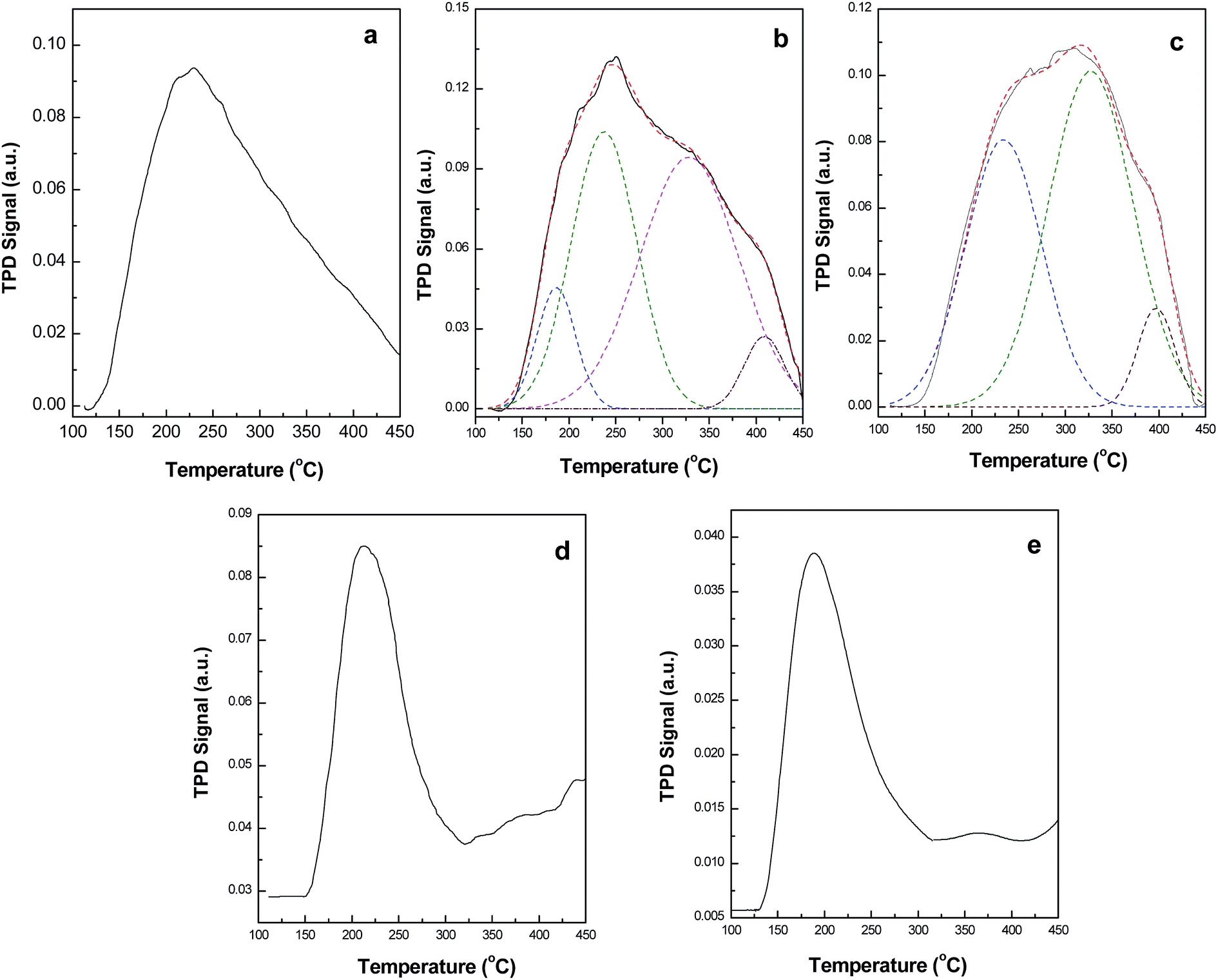
The number of acidic sites of the composite catalyst is evaluated using TPD of ammonia (Fig. 13). The TPD profile of sulfated zirconia exhibit an asymmetric peak with maxima at 228 °C (Fig. 13a). The incorporation of Fe2O3 into the zirconia lattice increases the high temperature ammonia desorption for the SFe5Zr and SFe10Zr samples. The SFe5Zr and SFe10Zr samples, exhibit two additional poorly resolved broad desorption peaks in the temperature range of 310–340 °C and 380–410 °C (Fig. 13b and c). The high temperature desorption features are significantly suppressed for SFe15Zr and SFe20Zr samples. The TPD method has been extensively used to study the acidic sites on sulfated zirconia.50–55 Although this method is ineffective for discrimination of the Lewis and Bronsted acidic sites, it is useful for quantitative determination of the acidic sites and their strength. Sulfated zirconia is known to exhibit different ammonia desorption regions.51–53 The low temperature desorption peak in the range of 50–200 °C has been assigned to NH3 desorption from Lewis acidic sites, whereas the desorption peak in the range of 250–450 °C and >500 °C has been ascribed to the presence of medium and strong acidic sites.52 Recent studies have shown that, the desorption peak beyond 500 °C is associated with evolution of significant amount of SO2 due to a redox reaction between the sulfate group and adsorbed ammonia molecules.54,55 The evolution of SO2 has been negligible upto 500 °C and the ammonia desorption data can be effectively correlated to the number of acidic sites. In the present study, the improved retention of the ammonia molecules in the temperature range of 250–450 °C can be ascribed to the formation  solid solution. The Fe–O–Zr bond occurring in the solid solution serves as potential sites for grafting of sulfate species. For SFe15Zr and SFe20Zr sample, the formation of separate α-Fe2O3 phase is observed in XRD with a consequent decrease in high temperature ammonia retention. This observation indicates that the dispersion of the iron oxide in zirconia lattice is important for generation of the acidic sites. The improvement in the acidity of SZ due to Fe3+ ion incorporation is in accordance with earlier literature study.18,51 The total number of acidic sites obtained from the TPD analysis is presented in Table 1. The acidity of the SFexZr materials varies in the order SFe10Zr ≈ SFe5Zr > SZr > SFe15Zr ≈ SFe20Zr > SFe.
 |
| | Fig. 13 Ammonia TPD profiles of (a) SZ, (b) SFe5Zr, (c) SFe10Zr, (d) SFe15Zr and (e) SFe20Zr. | |
Table 1 Physicochemical characteristics and catalytic activity of SFexZr materials
| Catalyst |
Surface area (m2 g−1) |
Aciditya (mmol g−1) |
Time (h) |
Yieldb,c (%) |
Rated (mmol h−1 m−2 × 10⁻³) |
Rate (mmol h−1 g−1) |
| Calculated from TPD of ammonia. Reaction condition: benzaldehyde (1 mmol), aniline (1 mmol), dimedone (2 mmol) and 50 mg catalyst in, 5 ml acetonitrile under reflux condition. Refers to pure and isolated yield. Calculated with respect to the benzaldehyde conversion in the reaction mixture analyzed using gas chromatography. |
| SZ |
62.1 |
0.31 |
04 |
62.0 |
4.83 |
5.8 |
| SFe5Zr |
131.1 |
0.39 |
03 |
75.0 |
3.60 |
10.0 |
| SFe10Zr |
95.3 |
0.40 |
2.5 |
80.5 |
6.54 |
12.2 |
| SFe15Zr |
89.6 |
0.26 |
03 |
70.8 |
4.20 |
7.6 |
| SFe20Zr |
67.5 |
0.24 |
04 |
52.2 |
3.80 |
5.2 |
| SFe |
44.8 |
0.19 |
04 |
42.1 |
3.50 |
3.2 |
3.2. Catalytic activity for synthesis of 1,8-dioxodecahydroacridines
The catalytic activity of the SFexZr material is examined for synthesis of 1,8-dioxodecahydroacridines by multicomponent one pot condensation of substituted benzaldehyde, dimedone and substituted anilines using acetonitrile as solvent under reflux conditions (Scheme 1). Initially, the condensation of benzaldehyde, dimedone and aniline is taken as a model reaction and the catalytic activity of different SFexZr materials is examined. Table 1 shows the physicochemical properties and catalytic activity of the SFexZr materials for the synthesis of 9,10-diphenyl-3,3,6,6-tetramethyl-10-phenyl-3,4,6,7,9,10-hexahydro-2H,5H-acridine-1,8-dione. Under identical reaction conditions, the SFe10Zr material is highly efficient for the condensation reaction giving 80.5% yield of the product in a minimum reaction time of 150 minutes. This catalytic composition also exhibit more number of acidic sites. In general, the composite oxides shows higher surface area and acidity compared to pure sulfated metal oxides. The increase in the surface area for SFexZr samples can be attributed to the prevention of grain growth during the hydrolysis step which is supported by Fourier study (Fig. 5). Moreover, the doping of Fe3+ ions is known to inhibit the sintering of the SZ particles.18 These factors can contribute to the enhancement of surface area for the SFexZr samples. The catalytic activities of the SFexZr materials correlate well with the surface acidity of the composite oxide. As observed from the XRD study, Fe3+ ions substitute Zr4+ ions in the ZrO2 lattice leading to formation of substitutional solid solution. The Fe–O–Zr sites in the solid solution phase can serve as potential sites for anchoring of the sulfate ions. In order to compare the catalytic activity of the SFexZr materials, the reaction rate are calculated in terms of unit surface area and acidic sites (Table 1). Among all SFexZr material, the SFe10Zr material exhibit highest reaction rate. Based on the results described in Table 1, the SFe10Zr catalyst is selected for further studies. The effect of various reaction parameters such as the catalyst amount, reaction media, time and temperature are evaluated to optimize the reaction parameters. The detail results of these experiments are presented in Fig. 14 and 15. For reaction involving 1 mmol of the benzaldehyde, 50 mg of the catalyst is found to be ideal for efficient multicomponent condensation. Further increase in the catalyst amount does not have any marked impact on the yield of the product (Fig. 14, Panel I). The effect of temperature on the catalytic activity is studied in the temperature range of 50–82 °C for the SFe10Zr catalyst. In general, the yield of the product increases with temperature and best value is obtained when the reaction is carried out under reflux condition (Fig. 14, Panel II). In order to study the effect of reaction media on the catalytic activity, solvents with different polarity are used in the optimized reaction protocol. The reaction yield is improved in presence of polar solvent as compared to the nonpolar solvent. The less yield observed in the aqueous media can be attributed to the limited solubility of the reactants in water. Among different solvent studied for the reaction, comparable yields of the dioxodecahydroacridines are obtained in acetonitrile and ethanol. Hence acetonitrile is chosen as the preferred reaction media. The effect of reaction time on the yield of the product was studied by conducting the reaction upto 5 h in acetonitrile under reflux condition (Fig. 15). As observed from Fig. 15, the SFe10Zr material display highest initial rate and better yield of the product in a short span of 3 h. After optimizing the reaction conditions, we explored the scope and limitation of the catalytic protocol by using different substituted aldehydes and anilines in the optimized protocol. Table 2 shows the yield of structurally diverse 1,8-dioxodecahydroacridines synthesized using SFe10Zr material as catalyst. It is observed that aniline substituted with electron donating groups is more active for the synthesis of dioxodecahydroacridines. However, the electronic effect due to presence of different substituted aromatic aldehydes does not have much impact over product yield. All the aryl aldehydes reacted smoothly in the optimized protocol to afford the corresponding dioxodecahydroacridines in high yield and purity. After completion of the reaction, the catalyst particles were filtered and regenerated by washing the used catalyst three times with 10 ml portions of ethyl acetate followed by calcination at 450 °C for 2 h. The recyclability of the SFe10Zr catalyst is studied for three consecutive cycles for the synthesis of 9,10-diphenyl-3,3,6,6-tetramethyl-10-phenyl-3,4,6,7,9,10-hexahydro-2H,5H-acridine-1,8-dione (Table 2, entry 1). The SFe10Zr catalyst is found to be recyclable for three cycles without any appreciable loss in catalytic activity (Table 2, entry 1, yields, 80.5%, 1st; 78%, 2nd; 75%, 3rd).
 |
| | Scheme 1 SFexZr catalyzed synthesis of 1,8-dioxodecahydroacridines by condensation of dimedone, substituted anilines and aryl aldehydes. | |
 |
| | Fig. 14 Effect of various reaction parameters on yield of the product for model reaction. (I) Effect of catalyst amount (MeCN, reflux condition), (II) effect of temperature (MeCN, 50 mg catalyst) and (III) effect reaction media (50 mg catalyst, for water and PEG reaction was carried out at 80 °C, for other solvent reflux condition was used). | |
 |
| | Fig. 15 Effect of reaction time on the yield of the 1,8-dioxodecahydroacridines. | |
Table 2 Synthesis of 1,8-dioxodecahydroacridines catalyzed by SFe10Zr material
| Sl. No. |
R1 |
R2 |
Time (min) |
Yield (%) |
| 1 |
H |
H |
150 |
80.5 |
| 2 |
4-NO2 |
H |
180 |
83.2 |
| 3 |
4-Cl |
H |
150 |
81.5 |
| 4 |
4-OCH3 |
H |
180 |
86.0 |
| 5 |
H |
CH3 |
150 |
85.6 |
| 6 |
4-NO2 |
CH3 |
150 |
88.2 |
| 7 |
4-Cl |
CH3 |
150 |
82.5 |
| 8 |
4-OCH3 |
CH3 |
150 |
89.5 |
| 9 |
H |
OCH3 |
150 |
86.5 |
| 10 |
4-NO2 |
OCH3 |
150 |
90.1 |
| 11 |
4-Cl |
OCH3 |
150 |
86.2 |
| 12 |
4-OCH3 |
OCH3 |
150 |
84.5 |
4. Conclusion
In the present investigation, we have prepared sulfate grafted Fe2O3–ZrO2 mixed oxide nanoparticles using urea as a mild base followed by post functionalization with sulfate species. The selective stabilization of the tetragonal phase of zirconia is observed for the iron doped zirconia samples. Upto 10 mol% Fe2O3 content, the iron ions substitute for the zirconium ions in ZrO2 lattice leading to the formation of an anion deficient solid solution. Beyond 10 mol% Fe2O3 content, the presence of hematite phase along with the solid solution phase is observed from the XRD study. The iron oxide component exists in a highly dispersed state in the form of nonstoichiometric nanoclusters with lattice distortion. The characteristic vibrational feature corresponding to the surface grafted bidentate sulfate species are inferred from FTIR study. XPS study confirmed the presence of grafted sulfate species on the composite oxide surface. TEM and Fourier line profile analysis study revealed presence of particles having near spherical morphology with size in the range of 10–30 nm. The mixed oxide system exhibit more number of acidic sites as well as higher catalytic activity than pure sulfated zirconia. The SFe10Zr composite oxide has been explored for a rapid, convenient and environmentally benign synthesis of biologically important 1,8-dioxodecahydroacridines in acetonitrile medium. The SFe10Zr catalyst is highly active for the multicomponent reactions generating structurally diverse 1,8-dioxodecahydroacridines with good yield and purity of the products. The protocol developed using SFe10Zr catalyst has been found to be advantageous in terms of simple experimentation, recyclable catalyst and high yield and purity of the synthesized compounds.
Acknowledgements
We thank IIP, Dehradun and IIT, Madras for providing necessary instrumental facilities and BRNS and NIT, Rourkela for funding.
References
- M. J. Climent, A. Corma and S. Iborra, Chem. Rev., 2011, 111, 1072–1133 CrossRef CAS PubMed.
- G. Busca, Chem. Rev., 2010, 110, 2217–2249 CrossRef CAS PubMed.
- S. Samantaray and B. G. Mishra, J. Mol. Catal. A: Chem., 2011, 339, 92–98 CrossRef CAS PubMed.
- B. M. Reddy and M. K. Patil, Chem. Rev., 2009, 109, 2185–2208 CrossRef CAS PubMed.
- N. Wang, Y. Yao, W. Li, Y. Yang, Z. Song, W. Liu, H. Wang, X.-F. Xia and H. Gao, RSC Adv., 2014, 4, 57164–57172 RSC.
- G. Morales, A. Osatiashtiani, B. Hernández, J. Iglesias, J. A. Melero, M. Paniagua, D. R. Brown, M. Granollers, A. F. Lee and K. Wilson, Chem. Commun., 2014, 50, 11742–11745 RSC.
- M. Ejtemaei, A. Tavakoli, N. Charchia, B. Bayatia, A. A. Babaluoa and Y. Bayata, Adv. Powder Technol., 2014, 25, 840–846 CrossRef CAS PubMed.
- G. D. Yadav and A. R. Yadav, Microporous Mesoporous Mater., 2014, 195, 180–190 CrossRef CAS PubMed.
- A. J. Ward, A. A. Pujari, L. Costanzo, A. F. Masters and T. Maschmeyer, Catal. Today, 2011, 178, 187–196 CrossRef CAS PubMed.
- M. Signoretto, A. Breda, F. Somma, F. Pinna and G. Cruciani, Microporous Mesoporous Mater., 2006, 91, 23–32 CrossRef CAS PubMed.
- C. Liu, S. Lee, D. Su, Z. Zhang, L. Pfefferle and G. L. Haller, J. Phys. Chem. C, 2012, 116, 21742–21752 CAS.
- M. Popova, Á. Szegedi, A. Ristić and N. N. Tušar, Catal. Sci. Technol., 2014, 4, 3993–4000 CAS.
- B. M. Reddy, G. K. Reddy, K. N. Rao and L. Katta, J. Mol. Catal. A: Chem., 2009, 306, 62–68 CrossRef CAS PubMed.
- F. H. Alhassan, U. Rashid and Y. H. Taufiq-Yap, Fuel, 2015, 142, 38–45 CrossRef CAS PubMed.
- Y. Kuwahara, W. Kaburagi, K. Nemotob and T. Fujitani, Appl. Catal., A, 2014, 476, 186–196 CrossRef CAS PubMed.
- S. Samantaray, P. Kar, G. Hota and B. G. Mishra, Ind. Eng. Chem. Res., 2013, 52, 58–62 CrossRef.
- H. Chen, Z. Ye, X. Cui and D. Yan, Microporous Mesoporous Mater., 2011, 143, 368–374 CrossRef CAS PubMed.
- N. Nagaraju and S. Z. M. Shamshuddin, Indian J. Chem. Technol., 2007, 14, 47–51 CAS.
- S. S. Kahandal, S. R. Kale, M. B. Gawande and R. V. Jayaram, Catal. Sci. Technol., 2014, 4, 672–680 CAS.
- S. Gao, P. Wang, X. Chen, H. Wang, Z. Wu, Y. Liu and X. Weng, Catal. Commun., 2014, 43, 223–226 CrossRef CAS PubMed.
- R. S. Rodrigo, E. L. Domínguez, F. E. L. Angel, J. N. Bola, G. Alamillaa, A. O. Sarabiac, J. A. M. Bandaa, L. C. Netro, G. Z. Ramírez and A. C. Mares, Catal. Today, 2015, 250, 197–208 CrossRef PubMed.
- J. Zhang, Y. Chen, X. Chen, X. Zheng, W. Cao, J. Chen and M. Zhang, Tetrahedron, 2014, 70, 5820–5827 CrossRef CAS PubMed.
- C. Fattorusso, et al., J. Med. Chem., 2008, 51, 1333–1343 CrossRef CAS PubMed.
- A. Adams, J. M. Guss, C. A. Collyer, W. A. Denny, A. S. Prakash and L. P. Wakelin, Mol. Pharmacol., 2000, 58, 649–658 CAS.
- X. Luan, C. Gao, N. Zhang, Y. Chen, Q. Sun, C. Tan, H. Liu, Y. Jin and Y. Jiang, Bioorg. Med. Chem., 2011, 19, 3312–3319 CrossRef CAS PubMed.
- H. Mohan, J. P. Mittal, N. Srividya and P. J. Ramamurthy, J. Phys. Chem., 1998, 102, 4444–4449 CrossRef CAS.
-
(a) M. A. Ghasemzadeh, J. S. Ghomi and H. Molaei, C. R. Chim., 2012, 15, 969–974 CrossRef CAS PubMed;
(b) K. B. Ramesh and M. A. Pasha, Bioorg. Med. Chem. Lett., 2014, 24, 3907–3913 CrossRef CAS PubMed;
(c) M. Hong and G. Xiao, J. Fluorine Chem., 2012, 144, 7–9 CrossRef CAS PubMed;
(d) B. Das, P. Thirupathi, I. Mahender, V. S. Reddy and Y. K. Rao, J. Mol. Catal. A: Chem., 2006, 247, 233–239 CrossRef CAS PubMed;
(e) M. Kidwai and D. Bhatnagar, Tetrahedron Lett., 2010, 51, 2700–2703 CrossRef CAS PubMed;
(f) T. S. Jin, J. S. Zhang, T. T. Guo, A. Q. Wang and T. S. Li, Synthesis, 2004, 2001–2005 CrossRef CAS;
(g) M. Dabiri, M. Baghbanzadeh and E. Arzroomchilar, Catal. Commun., 2008, 9, 939–942 CrossRef CAS PubMed.
- S. Samantaray, G. Hota and B. G. Mishra, Catal. Commun., 2011, 12, 1255–1259 CrossRef CAS PubMed.
- L. Chen, J. Hu and R. M. Richards, ChemPhysChem, 2008, 9, 1069–1078 CrossRef CAS PubMed.
- R. Srinivasan, T. Watkins, C. R. Hubbard and B. Davis, Chem. Mater., 1995, 7, 725–730 CrossRef CAS.
- J. A. Navío, M. C. Hidalgo, G. Colón, S. G. Botta and M. I. Litter, Langmuir, 2001, 17, 202–210 CrossRef.
- B. E. Warren and B. L. Averbach, J. Appl. Phys., 1950, 21, 595 CrossRef CAS PubMed.
- D. Balzar and H. Ledbetter, J. Appl. Crystallogr., 1993, 26, 97–103 CrossRef.
- I. E. Wachs, Colloids Surf., A, 1995, 105, 143–149 CrossRef CAS.
- S. V. Jadhav, K. M. Jinka and H. C. Bajaj, Appl. Catal., A, 2010, 309, 158–165 CrossRef PubMed.
- M. Hino, M. Kurashige, H. Matsuhash and K. Arata, Thermochim. Acta, 2006, 441, 35–41 CrossRef CAS PubMed.
- S. Ardizzone and C. L. Bianchi, Appl. Surf. Sci., 1999, 152, 63–69 CrossRef CAS.
- M. A. Ecormier, K. Wilson and A. F. Lee, J. Catal., 2003, 215, 57–65 CrossRef CAS.
- F. H. Alhassan, U. Rashidc, M. S. Al-Qubaisi, A. Rasedee and Y. H. Taufiq-Yap, Powder Technol., 2014, 253, 809–813 CrossRef CAS PubMed.
- D. R. Milburn, R. A. Keogh, D. E. Sparks and B. H. Davis, Appl. Surf. Sci., 1998, 126, 11–15 CrossRef CAS.
- X. Hu, J. C. Yu, J. Gong, Q. Li and G. Li, Adv. Mater., 2007, 19, 2324–2329 CrossRef CAS PubMed.
- A. M. Jubb and H. C. Allen, ACS Appl. Mater. Interfaces, 2010, 2, 2804–2812 CAS.
- H. M. Fan, G. J. You, Y. Li, Z. Zheng, H. R. Tan, Z. X. Shen, S. H. Tang and Y. P. Feng, J. Phys. Chem. C, 2009, 113, 9928–9935 CAS.
- I. S. Imkiene, M. Treideris, G. Niaura, R. Szymczak, P. Aleshkevych, A. Reza, I. Kasalynas, V. Bukauskas and G. J. Babonas, Mater. Chem. Phys., 2011, 130, 1026–1032 CrossRef PubMed.
- D. Spielbauer, G. A. H. Mekhemer, E. Bosch and H. Knozinger, Catal. Lett., 1996, 36, 59–68 CrossRef CAS.
- D. Bersani, P. P. Lottici and X. Z. Ding, Appl. Phys. Lett., 1998, 72, 73–75 CrossRef CAS PubMed.
- S. Bordiga, R. Buzzoni, F. Geobaldo, C. Lamberti, E. Giamello, C. Zecchina, G. Leofanti, G. Petrini, G. Tozzola and G. Vlaic, J. Catal., 1996, 158, 486–501 CrossRef CAS.
- M. S. Kumar, M. Schwidder, W. Grunert and A. Bruckner, J. Catal., 2004, 227, 384–397 CrossRef CAS PubMed.
- A. Gervasini, C. Messi, P. Carniti, A. Ponti, N. Ravasio and F. Zaccheria, J. Catal., 2009, 262, 224–234 CrossRef CAS PubMed.
- N. Katada, J. Endo, K. Notsu, N. Yasunobu, N. Naito and M. Niwa, J. Phys. Chem. B, 2000, 104, 10321–10328 CrossRef CAS.
- W. H. Chen, H. H. Ko, A. Sakthivel, S. J. Huang, S. H. Liu, A. Y. Lo, T. C. Tsai and S. B. Liu, Catal. Today, 2006, 116, 111–120 CrossRef CAS PubMed.
- V. S. Marakatti, G. V. Shanbhag and A. B. Halgeri, Appl. Catal., A, 2013, 451, 71–78 CrossRef CAS PubMed.
- V. G. Deshmane and Y. G. Adewuyi, Appl. Catal., A, 2013, 462, 196–206 CrossRef PubMed.
- B. T. Loveless, A. Gyanani and D. S. Muggli, Appl. Catal., B, 2008, 84, 591–597 CrossRef CAS PubMed.
- M. Yu Smirnova, A. V. Toktarev, A. B. Ayupov and G. V. Echevsky, Catal. Today, 2010, 152, 17–23 CrossRef PubMed.
|
| This journal is © The Royal Society of Chemistry 2015 |
Click here to see how this site uses Cookies. View our privacy policy here. 
 whereas for SFe15Zr and SFe20Zr materials a mixture of solid solution and hematite phase exist in the sulfate grafted samples. The crystallite sizes and rms stains for the SFexZr samples are calculated from the Fourier line profile analysis of the XRD patterns by Warren and Averbach method using software BRAEDTH.32,33 The Fourier line profile analysis is carried out by taking the ZrO2 T (111) and T (220) peaks for all composite oxide samples. The plot of distribution function (PV), and size coefficient (AS) as function of the Fourier length (L) for the SFexZr samples are presented in Fig. 4 panel I and II, respectively. The SFe5Zr and SFe10Zr materials exhibit narrow distribution functions, the distribution being confined upto Fourier length of 30 nm (Fig. 4I). This observation indicates that these materials contain a major fraction of the crystallites with size less than 30 nm. In contrast to this observation, the SFe15Zr and SFe20Zr materials show wide distribution function indicating presence of polycrystalline particles with larger average crystallite size. Fig. 5 represents a plot of the crystallite size and rms strain plotted against the iron content in the SFexZr materials. The SFexZr material exhibits average crystallite sizes in the range of 10–30 nm. The crystallite size of the mixed oxide materials increases with iron oxide content. The calculated rms strain exhibit an inverse correlation with the crystallite size. The higher strain observed for SFe5Zr and SFe10Zr materials can be ascribed to different types of random and local lattice distortion in zirconia nanocrystallites.


 solid solution. The Fe–O–Zr bond occurring in the solid solution serves as potential sites for grafting of sulfate species. For SFe15Zr and SFe20Zr sample, the formation of separate α-Fe2O3 phase is observed in XRD with a consequent decrease in high temperature ammonia retention. This observation indicates that the dispersion of the iron oxide in zirconia lattice is important for generation of the acidic sites. The improvement in the acidity of SZ due to Fe3+ ion incorporation is in accordance with earlier literature study.18,51 The total number of acidic sites obtained from the TPD analysis is presented in Table 1. The acidity of the SFexZr materials varies in the order SFe10Zr ≈ SFe5Zr > SZr > SFe15Zr ≈ SFe20Zr > SFe.