
 Open Access Article
 This Open Access Article is licensed under a
 Creative Commons Attribution 3.0 Unported Licence
Fabrication of bioactive polypyrrole microelectrodes on insulating surfaces by surface-guided biocatalytical polymerization†
T.
Galán
abc,
A.
Lagunas
*ba,
E.
Martinez
dbc and
J.
Samitier
abc
aNanobioengineering Group, Institute for Bioengineering of Catalonia (IBEC), Baldiri Reixac 15-21, Barcelona 08028, Spain. E-mail: alagunas@ibecbarcelona.eu
bNetworking Biomedical Research Center in Bioengineering, Biomaterials and Nanomedicine (CIBER-BBN), Spain
cElectronics Department, University of Barcelona (UB), Martí i Franquès 1-11, Barcelona 08028, Spain
dBiomimetic Systems for Cell Engineering Group, Institute for Bioengineering of Catalonia (IBEC), Baldiri Reixac 15-21, Barcelona 08028, Spain
First published on 30th July 2015
Abstract
Although promising, organic microelectronics lack standard fabrication methods comparable to photolithography in terms of resolution. Here we propose a novel and easily scalable on-surface biocatalytical procedure for the fabrication of polypyrrole microelectrodes on insulating surfaces. Arrays of polypyrrole microelectrodes were obtained by surface-guided biocatalytical polymerization, achieving up to 5 μm in resolution and conductivities up to 3 S cm−1. The mild reaction conditions provided by the biocatalytical approach permit the entrapment of bioactive compounds during polymer synthesis. This system is convenient for drug release purposes, as demonstrated by the controlled release of entrapped biotin through electrical stimulation. These results pave the way for the application of polypyrrole microelectrodes produced through biocatalysis in the development of implantable devices for remotely controlled tissue interactions.
Introduction
Conducting polymers have emerged as a versatile alternative to metals and inorganic semiconductors for biomedical applications.1,2 In particular, they have been used as coatings for implantable metallic electrodes to improve bio-integration, and they sometimes include bioactive compounds for increased device performance.3 However, the development of a simple and robust process for the fabrication of conductive polymeric microelectrodes remains a challenge. Conventional photolithographic methods for microfabrication are not suitable for polymers, as they are prone to degradation upon exposure to radiation.4 Direct printing methods, such as ink-jet printing, offer an attractive alternative for the fabrication of conducting polymer microelectrodes.5,6 However, the polymer solubility in the carrier fluid and the ink-wetting characteristics limit the patterning resolution to 20–50 μm.7 In a different approach, conducting polymers have been grown on-surface by oxidative electrochemical polymerization.8,9 This technique provides high quality conducting polymers with satisfactory spatial resolution; however, it is restricted to electrically conductive surfaces. With respect to insulating surfaces, oxidative chemical polymerization results in polymers with poor electrical performance.10–12 Moreover, this process is conducted under harsh reaction conditions, thereby limiting the introduction of bioactive compounds during polymer growth.Recently, biocatalysis has been explored as an environmentally respectful option for the synthesis of conducting polymers in solution, compatible with the in situ incorporation of biomolecules.13 It offers the possibility of working in aqueous media, under mild reaction conditions, with low by-product formation and without compromising the electric performance of the polymer. Conductivities up to 10 S cm−1 have been reported for biocatalytically produced polyaniline,14 and up to 3 S cm−1 for polypyrrole.15 Although polypyrrole films produced through biocatalysis have been shown to deposit on the reaction container during synthesis,16 no selective surface deposition has been addressed to date. Therefore, the development of reliable technologies for the controlled surface deposition of biocatalytically produced polypyrrole is an unmet need toward its use in functional bioactive devices.
Here, we report a method for the fabrication of polypyrrole microelectrodes by surface-guided biocatalytical polymerization. This procedure allows the fabrication of microelectrode arrays on insulating surfaces under mild reaction conditions, achieving feature resolutions comparable to those achieved using conventional contact lithographic methods. Microelectrode dimensions are controlled by tuning surface adhesion through a micropattern of a non-adhesive hydrophobic fluorosilane and an adhesive pyrrole-bearing silane. The benefits of the mild reaction conditions offered by the enzymatic polymerization method are demonstrated by the entrapment of biotin during the polymer synthesis. As a proof of concept, we used polypyrrole electrodes to control the release of biotin through cyclic voltammetry. Our results reveal that this system allows the controllable drug delivery through electrical stimulation, thus opening up wide applications in the biomedical field.
Results and discussion
The fabrication of polypyrrole microelectrodes by surface-guided biocatalytical polymerization is depicted in Fig. 1. Briefly, activated SiO2 surfaces were selectively patterned with the non-adhesive hydrophobic fluorosilane trichloro(1H,1H,2H,2H-perfluoro octyl)silane (FDTES) by microcontact printing (μCP). Fluorine-containing silanes, as the one employed here, have been reported for their hydrophobic and non-adhesive properties in different fabrication processes.17,18 Non-patterned regions, defining final microelectrode dimensions, were reacted with N-(3-trimethoxysilylpropyl)pyrrole (pyrrole-silane) by the vapor phase method and biocatalytical polymerization was then conducted on silane-micropatterned surfaces. Biocatalytical polymerization of pyrrole was performed using the enzyme horseradish peroxidase (HRP) with hydrogen peroxide (H2O2) as a substrate, in the presence of 2,2′-azinobis(3-ethylbenzothiazoline-6-sulfonate) (ABTS) as a redox mediator. This mediator was required due to the high oxidation potential of pyrrole, which hampered the direct reaction between the enzyme and the monomer.19,20 It is known that redox mediators get trapped in the final conducting polymer structure, acting as dopants and introducing some structural features that influence the physico-chemical properties of the polymer. Specifically, in the enzymatic synthesis of polypyrrole, ABTS proved to favor film formation against oligomeric precipitates in solution.13 Therefore, ABTS is a suitable candidate to achieve homogenous growth of the polymer on the surface. | ||
| Fig. 1 Site-selective deposition of biocatalytically produced polypyrrole microelectrodes on insulating SiO2 surfaces. Schematics of the procedure that include from left to right: μCP of fluorosilane FDTES, backfilling with pyrrole-silane and polymerization of pyrrole. | ||
The site-selective growth of polypyrrole on the regions containing pyrrole-silane was demonstrated by time-of-flight secondary ion mass spectrometry (ToF-SIMS) analysis (Fig. 2). ToF-SIMS surface images (Fig. 2a) and the corresponding ion mass spectra (Fig. 2b), normalized to the fluoride signal (F−, m/z = 19), at each step of the fabrication process are shown. After μCP, a pattern of fluoride ions (F−) corresponding to FDTES was observed on the SiO2 substrate (O−). When the remaining SiO2 areas were backfilled with pyrrole-silane, ToF-SIMS images showed a CN− signal (m/z = 26) associated with the pyrrole ring, clearly distinguished from the FDTES signal. After the biocatalytical polymerization has been conducted on the silanized surfaces, the ToF-SIMS spectrum showed an increase in the intensity of the CN− signal and the presence of high mass ions as a result of polypyrrole (CNO− at m/z = 42 and C3N− at m/z = 50).21,22 The corresponding ToF-SIMS surface image showed the alternation of FDTES ions (F−) and CN− ions, thus revealing that the structure of the micropattern has been preserved.
 | ||
| Fig. 2 Site-selective deposition of biocatalytically produced polypyrrole microelectrodes on insulating SiO2 surfaces. (a) Representative ToF-SIMS images of the indicated ions, obtained after each fabrication step. Scale bar = 15 μm. (b) Representative ToF-SIMS spectra obtained after each fabrication step and highlighting the material of which the samples comprised. | ||
The versatility of the surface-guided biocatalytical growth of polypyrrole microelectrodes was validated on various pattern dimensions (Fig. 3). Resolutions up to 5 μm were obtained, with a yield of 77% and an edge roughness value of 0.25 ± 0.07 μm (see Experimental section and ESI Fig. S3†). The resolution is comparable to that obtained with contact lithography.
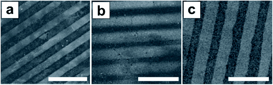 | ||
| Fig. 3 The versatility of the site-selective deposition of biocatalytically produced polypyrrole microelectrodes was validated using various pattern dimensions. Representative SEM images of (a) 20 μm-width lines with 20 μm pitch (scale bar = 100 μm), (b) 5 μm-width lines with 1 μm pitch (scale bar = 15 μm), and (c) 5 μm-width lines with 5 μm pitch (scale bar = 20 μm). | ||
A thickness value of 31 ± 4 nm was obtained for the polypyrrole micropatterns (5 μm-width lines) analyzed by atomic force microscopy (AFM) (Fig. 4). The thickness analysis of polypyrrole thin films grown onto pyrrole-silane monolayers showed a plateau of 75 nm reached after 60 min of reaction (see ESI Fig. S4†). Nevertheless, after sonication in Milli-Q water, thickness values decreased to a constant value of 31 nm, indicating that approximately only the first 30 nm of polypyrrole was tightly bound to the surface.
 | ||
| Fig. 4 AFM profile of biocatalytically produced polypyrrole microelectrodes. Polypyrrole microelectrodes showed an average thickness of 31 nm. Inset shows corresponding AFM topographical image. | ||
X-ray photoelectron spectroscopy (XPS) analysis was conducted on biocatalytically surface-grown polypyrrole thin films to analyze the elemental composition of the polymer (Fig. 5). Wide-scan spectra showed the presence of seven main peaks, identified with carbon (C 1s), oxygen (O 1s), silicon (Si 2s and Si 2p), nitrogen (N 1s) and sulphur (S 2s and S 2p). The existence of sulphur in the sample, indicates the presence of ABTS, which behaves as a dopant (Fig. 5a).13 The N 1s signal deconvolution (Fig. 5b) resulted in 28% of positively charged atomic nitrogen, which is in good agreement with the 25–33% reported for fully doped polypyrrole.16
 | ||
| Fig. 5 XPS analysis of biocatalytically synthesized polypyrrole thin films. (a) Wide-scan spectrum, and (b) N 1s core-level deconvolution showing the N+ components of the doped polypyrrole structure. | ||
The biocatalytically surface-grown polypyrrole films were conductive, as evidenced by the current–voltage (I–V) characteristics obtained (Fig. 6a), thereby indicating that they obeyed Ohm's law, showing negligible contact resistance with the external electrodes. The electrical conductivity of the films was calculated from eqn (1),
| σ = l/(A × R) | (1) |
 | ||
| Fig. 6 Electrical and electrochemical behavior of biocatalytically surface-grown polypyrrole films. (a) I–V characteristic of a polypyrrole film obtained by two contact measurement. (b) Redox wave for a polypyrrole film in PBS, at a scan rate of 100 mV s−1, showing oxidation and reduction reactions. | ||
Additionally, the electrochemical behavior of the films was monitored by cyclic voltammetry (CV) in phosphate buffered saline (PBS). Fig. 6b shows a cyclic voltammogram, where the oxidation and reduction reactions of the biocatalytically grown polypyrrole thin films were found at +0.45 and −0.71 V respectively. Broad redox waves, as the ones obtained here, have been observed in other polypyrrole films grown by different synthetic methods, showing also large separation between the redox responses of the polymer, according to the process shown in Scheme 1.2,23
 | ||
| Scheme 1 Redox reaction of polypyrrole doped with dopant A−. | ||
Taking advantage of the mild reaction conditions offered by the biocatalytical polymerization (aqueous media and pH values within the physiological range), biomolecule entrapment during the growth of the polymer was attempted. Entrapment provides a reasonably stable and homogeneous distribution of the biomolecule within the polymer matrix, while allowing its controlled release under certain conditions.24 Biotin entrapment was conducted by saturating the initial reaction mixture with biotin. The presence of biotin within the polypyrrole matrix was confirmed by XPS (see ESI Fig. S5†). In the presence of biotin, 20 μm-width lines of biocatalytically produced polypyrrole were fabricated (Fig. 7a). However, the structural stability of the polypyrrole microelectrodes obtained was hindered by the presence of the entrapped biotin, in the sense that they easily lifted off the surface and required an accurate control of the ultrasonic cleaning step. The effect of molecule entrapment on the polymer adhesion properties has been previously described for electrochemically grown polypyrrole, which also required fine tuning of the experimental conditions.2
 | ||
| Fig. 7 Electrically controlled release of biotin from biocatalytically produced polypyrrole microelectrodes. (a) Representative SEM image of 20 μm-width lines of site-selective biocatalytically surface-grown polypyrrole in the presence of biotin (scale bar = 100 μm). (b) Series of CVs (at 2 scans in green, 8 scans in blue and 25 scans in red) performed on the biotin-modified polypyrrole electrodes, showing the reduction in the electro-activity caused by biotin release. (c) Plot of the evolution of the characteristic peak area fragment at m/z = 245.09 of biotin, obtained from HPLC-MS analysis of the electrolyte solution at various time-points during the reduction step (solid red line), oxidation step (dashed green line), and without electrical stimulation (dashed black line). Results show that biotin release caused by passive ion exchange or during the oxidation step is minimal. | ||
The electrochemical switching between the oxidized and reduced states of polypyrrole, triggered by a cycling pulsed potential, allows the release of small doping molecules such as biotin from the polymer structure.25 During reduction, negative potentials neutralize the positive charge of the polymer backbone and thus eliminate the electrostatic interaction between polypyrrole and the doping anion of interest (in this case biotin), thus allowing the latter to freely diffuse and be released from the polymer matrix (Scheme 1).26 We performed controlled biotin release studies on biotin-modified polypyrrole electrodes by CV. Fig. 7b shows a sequence of cyclic voltammograms conducted in PBS solution. By increasing the number of scans, the electro-activity of the polymer was reduced due to the release of biotin to the surrounding medium. This was confirmed by monitoring the presence of biotin into the electrolyte solution after a reduction step at various time-points by means of high performance liquid chromatography mass spectrometry (HPLC-MS) analysis. The area of the characteristic biotin fragment (m/z = 245.09), normalized to the maximum value, is plotted against time in Fig. 7c. Control experiments were also performed, consisting on quantification of biotin release during an oxidation step (constant oxidation process at +0.9 V) and quantification of biotin release by diffusion without electrical stimulation. The identification of such mass fragments (entire mass of biotin) within the electrolyte solution after release experiments confirmed the integrity of biotin after entrapment and release processes. The biotin presence in solution increased abruptly within the first 5 min of the cathodic stimulation (more than 80% of biotin was released from the polypyrrole electrode), reaching a saturation value and suggesting the total release of biotin after the process. This result is in agreement with previously reported release studies in thin polymer layers where the evolution of dopants is not limited by diffusion through the polymer matrix.2 Moreover, we observed a minimal biotin release during the oxidation step (0.4%) and during the non-electrically stimulated experiment (9%). These findings demonstrate the voltage-dependent release behavior of the biocatalytically produced polypyrrole electrodes.
Conclusions
Here we describe an effective strategy for the fabrication of polypyrrole microelectrodes by surface-guided biocatalytical polymerization onto insulating surfaces. The surface-guided growth of polypyrrole microelectrodes with up to 5 μm resolution, a value comparable to that obtained with contact lithography, was achieved by the μCP of an adhesive/non-adhesive micropattern of silanes. Our results show that fully doped polypyrrole was obtained, exhibiting conductivity values comparable to those reported for the in-solution biocatalytically produced polypyrrole. Biotin entrapment was conducted taking advantage of the mild reaction conditions of enzymatic catalysis and controllable drug release experiments were successfully performed by the application of an external electric field. These promising results pave the way to the development of bioactive arrays of microelectrodes based on conducting polymers, which could be incorporated in implantable devices for remotely controlled tissue interactions.Experimental
Materials
SiO2/Si (1 μm thick SiO2) substrates were supplied by Siltronix (Archamps, France). H2SO4 95–98% and ethanol 96% were from Panreac Química S.A.U. (Barcelona, Spain). 33% w/v H2O2 was from BASF (Barcelona, Spain). Sylgard® 184 Silicone Elastomer Kit for polydimethylsiloxane (PDMS) stamp fabrication was supplied by Dow Corning (Seneffe, Belgium). Trichloro(1H,1H,2H,2H-perfluoro octyl)silane (FDTES), pyrrole, 2,2′-azinobis(3-ethylbenzothiazoline-6-sulfonate) (ABTS), ethylenediaminetetraacetic acid (EDTA), potassium biphthalate buffer, horseradish peroxidase (HRP; brown powder, 50–150 units mg−1, pyrogallol units) and D-biotin were purchased from Sigma-Aldrich Química S.A. (Madrid, Spain). N-(3-Trimethoxysilylpropyl)pyrrole (pyrrole-silane) was from ABCR GmbH & CO. KG. (Karlsruhe, Germany). Phosphate buffered saline (PBS) was supplied by Invitrogen S. A. (Barcelona, Spain).Site-selective growth of biocatalytically generated polypyrrole microelectrodes
Microelectrode dimensions were defined by microcontact printing (μCP). SiO2 substrates were cleaned in piranha acid (3![[thin space (1/6-em)]](https://www.rsc.org/images/entities/char_2009.gif) :1 v/v solution of H2SO4 and H2O2) for 15 min, rinsed with copious amounts of Milli-Q water and dried with pressurized air. Caution: piranha acid is a strong oxidizer and a strong acid. It should be handled with extreme care, as it reacts violently with most organic materials. PDMS stamps were fabricated following standard procedures.27 For printing, PDMS stamps were cleaned in ethanol and incubated in a solution (5 mM) of FDTES for 5 min at room temperature. Stamps were dried with pressurized air and brought into contact with activated SiO2 surfaces for 5 min. The surfaces were then washed with ethanol and dried with pressurized air. Non-patterned regions were reacted with pyrrole-silane by vapor-phase assembly28 and annealed for 1 h at 80 °C. Micropatterned SiO2 substrates were submerged in a degassed solution of freshly distilled pyrrole (233 μL, 3.35 mmol), ABTS (67.2 mg, 0.12 mmol), and EDTA (12.2 mg, 0.04 mmol) in potassium biphthalate buffer (15 mL, pH = 4.0) under argon atmosphere at room temperature. Afterwards, HRP (7.3 mg) dissolved in degassed PBS (1.7 mL, pH = 7.0) was added. Polymerization was initiated by the addition of H2O2 (390 μL) in a fed-batch mode. After 60 min under mechanical stirring at room temperature, substrates were ultrasonically cleaned in Milli-Q water to remove any polypyrrole poorly attached to the surface and then dried with pressurized air. For characterization purposes, polypyrrole thin films were also grown on pyrrole-silane monolayers.
:1 v/v solution of H2SO4 and H2O2) for 15 min, rinsed with copious amounts of Milli-Q water and dried with pressurized air. Caution: piranha acid is a strong oxidizer and a strong acid. It should be handled with extreme care, as it reacts violently with most organic materials. PDMS stamps were fabricated following standard procedures.27 For printing, PDMS stamps were cleaned in ethanol and incubated in a solution (5 mM) of FDTES for 5 min at room temperature. Stamps were dried with pressurized air and brought into contact with activated SiO2 surfaces for 5 min. The surfaces were then washed with ethanol and dried with pressurized air. Non-patterned regions were reacted with pyrrole-silane by vapor-phase assembly28 and annealed for 1 h at 80 °C. Micropatterned SiO2 substrates were submerged in a degassed solution of freshly distilled pyrrole (233 μL, 3.35 mmol), ABTS (67.2 mg, 0.12 mmol), and EDTA (12.2 mg, 0.04 mmol) in potassium biphthalate buffer (15 mL, pH = 4.0) under argon atmosphere at room temperature. Afterwards, HRP (7.3 mg) dissolved in degassed PBS (1.7 mL, pH = 7.0) was added. Polymerization was initiated by the addition of H2O2 (390 μL) in a fed-batch mode. After 60 min under mechanical stirring at room temperature, substrates were ultrasonically cleaned in Milli-Q water to remove any polypyrrole poorly attached to the surface and then dried with pressurized air. For characterization purposes, polypyrrole thin films were also grown on pyrrole-silane monolayers.
Characterization of biocatalytically generated polypyrrole electrodes
Micropatterned substrates were imaged by scanning electron microscopy (SEM) in a Nova NanoSEM™ 230-FEI field-emission SEM operated at 5 kV (FEI™) and by atomic force microscopy (AFM) in a Dimension 3100 AFM instrument (Veeco Instruments) operated in tapping mode in air. Silicon AFM probes (Budget Sensors) with a spring constant k = 40 N m−1 and a resonant frequency ν = 300 kHz were used. ImageJ software was used to obtain edge roughness values corresponding to polypyrrole lines of 5 μm wide. The stripe analysis plugging was used and AFM images, corresponding to scanned areas of 20 μm × 20 μm, were processed. Images were first calibrated to calculate the pixel to nm ratio. The images were then converted to a binary map and line edge analysis was performed.29Surface chemical analysis was performed using time-of-flight secondary ion mass spectrometry (ToF-SIMS) in a ToF-SIMS IV instrument (ION-TOF GmbH) with pulsed bismuth liquid metal ion source (Bi3+) operated at 25 keV at a pressure of 5 × 10⁻⁹ mbar and equipped with a reflection ToF analyzer, a multichannel plate and time-to-digital converter. Chemical composition was also analyzed by X-ray photoelectron spectroscopy (XPS) using a Perkin-Elmer PHI 5500 Multitechnique System from Physical Electronics with a monochromatic X-ray source (aluminum KR line of 1486.6 eV energy and 350 W). Nitrogen 1s core-level scan and sulfur 2p core-level scan spectra were recorded. All measurements were taken in an ultra-high vacuum chamber pressure between 7 × 10⁻⁹ and 3 × 10⁻⁸ mbar. Peak fitting was performed using MultiPak V6.0A software from Physical Electronics Inc.
Direct current electrical measurements were conducted on polypyrrole thin films grown on silanized (pyrrole-silane) SiO2 surfaces, which were confined in the space between two square gold electrodes in a 2-contact geometry (see ESI Fig. S1† for details). The conductivity values obtained in this work were calculated from resistances in the order of hundreds of kOhms. Taking into account that the contact resistance of the leads is only significant when the resistance under study is below 100 Ohms approx.,30 it was considered that a 2-contact measurement was enough to extract representative conductivity values. A S-100 analytical probing station from Signatone Corporation, with tungsten probes T20-50 with a 5 μm radius tip (Everbeing INT'L Corporation), was used to measure resistance. Electrical conductivity was calculated by applying eqn (1).
Results are given as the average ± standard deviation resulting from the measurement of at least three independent samples (three measures per sample).
Biotin entrapment and release
Biotin entrapment was performed by saturating the initial degassed pyrrole, ABTS and EDTA solution in potassium biphthalate buffer (pH = 4.0) with D-biotin (8.2 mM). This solution was maintained under argon at room temperature. As described, HRP in degassed PBS (pH = 7.0) was added and the polymerization was initiated by the addition of H2O2. After 60 min under mechanical stirring at room temperature, substrates were ultrasonically cleaned in Milli-Q water and dried with pressurized air.Controlled biotin release experiments were conducted by cyclic voltammetry (CV) in a BioLogic SP150 electrochemical analysis system (Science Instruments, France). Measurements were done in PBS buffer, and voltage sweeps from −0.9 V to +0.9 V and vice versa were applied to the polymeric working electrode at a scan speed of 100 mV s−1 (see Fig. S2 in the ESI† for details on the experimental setup). Changes in current intensity were registered against applied potential versus Ag/AgCl reference electrode and processed with OriginPro 8.5.0 SR1 (OriginLab Corp). Samples from the supernatant solution (200 μL) close to the working electrode were taken between 1 and 25 min during the reduction step and analyzed by high performance liquid chromatography-mass spectrometry (HPLC-MS). Control experiments were conducted in the absence of electrical stimulation and by the application of a constant oxidation potential of 0.9 V. HPLC-MS calibration experiments using free biotin in PBS were performed before entrapment and release experiments, to determine the exact mass of biotin before polymerization.
Acknowledgements
This work was supported by Networking Biomedical Research Center in Bioengineering, Biomaterials and Nanomedicine (CIBER-BBN), Spain. The Nanobioengineering group at the Institute for Bioengineering of Catalonia (IBEC) receives support from the Spanish Ministry of Science and Education and the Commission for Universities and Research of the Department of Innovation, Universities and Enterprise of the Generalitat de Catalunya (No. 2014 SGR 1442). In addition, the research received support from the Spanish Ministry of Economy and Competitiveness, OLIGOCODES (MAT2012-38573-C02) and MINAHE5 (TEC2014-51940-C2-2-R), and the Fundación Botín, Santander, Spain.Notes and references
- N. Huebsch and D. J. Mooney, Nature, 2009, 462, 426–432 CrossRef CAS PubMed.
- B. C. Thompson, S. E. Moulton, J. Ding, R. Richardson, A. Cameron, S. O'Leary, G. G. Wallace and G. M. Clark, J. Controlled Release, 2006, 116, 285–294 CrossRef CAS PubMed.
- V. S. Polikov, P. A. Tresco and W. M. Reichert, J. Neurosci. Methods, 2005, 148, 1–18 CrossRef PubMed.
- R. S. Johnson, D. R. Wheeler and S. M. Dirk, J. Mater. Chem. C, 2013, 1, 1428–1433 RSC.
- T. R. Hebner, C. C. Wu, D. Marcy, M. H. Lu and J. C. Sturm, Appl. Phys. Lett., 1998, 72, 519–521 CrossRef CAS.
- Y. Yang, S. Chang, J. Bharathan and J. I. E. Liu, J. Mater. Sci.: Mater. Electron., 2000, 1, 89–96 CrossRef.
- H. Sirringhaus, Science, 2000, 290, 2123–2126 CrossRef CAS PubMed.
- S. M. Richardson-Burns, J. L. Hendricks, B. Foster, L. K. Povlich, D. H. Kim and D. C. Martin, Biomaterials, 2007, 28, 1539–1552 CrossRef CAS PubMed.
- L. Sasso, A. Heiskanen, F. Diazzi, M. Dimaki, J. Castillo-León, M. Vergani, E. Landini, R. Raiteri, G. Ferrari, M. Carminati, M. Sampietro, W. E. Svendsen and J. Emnéus, Analyst, 2013, 138, 3651–3659 RSC.
- Z. Huang, P. Wang, A. G. Macdiarmid, Y. Xia and G. Whitesides, Langmuir, 1997, 7463, 6480–6484 CrossRef.
- S. Kwon, J. W. Ha, J. Noh and S. Y. Lee, Appl. Surf. Sci., 2010, 257, 165–171 CrossRef CAS.
- R. Ravichandran, S. Sundarrajan, J. R. Venugopal, S. Mukherjee and S. Ramakrishna, J. R. Soc., Interface, 2010, 7(suppl. 5), S559–S579 CrossRef CAS PubMed.
- H. K. Song and G. T. R. Palmore, J. Phys. Chem. B, 2005, 109, 19278–19287 CrossRef CAS PubMed.
- S. K. Sahoo, R. Nagarajan, S. Roy, L. A. Samuelson, J. Kumar and A. L. Cholli, Macromolecules, 2004, 37, 4130–4138 CrossRef CAS.
- R. Bouldin, S. Ravichandran, A. Kokil, R. Garhwal, S. Nagarajan, J. Kumar, F. F. Bruno, L. A. Samuelson and R. Nagarajan, Synth. Met., 2011, 161, 1611–1617 CrossRef CAS.
- R. Cruz-Silva, E. Amaro, A. Escamilla, M. E. Nicho, S. Sepulveda-Guzman, L. Arizmendi, J. Romero-Garcia, F. F. Castillon-Barraza and M. H. Farias, J. Colloid Interface Sci., 2008, 328, 263–269 CrossRef CAS PubMed.
- M. Estévez, I. Fernández-Ulibarri, E. Martínez, G. Egea and J. Samitier, Soft Matter, 2010, 6, 582–590 RSC.
- G. J. Zhang, T. Tanii, T. Zako, T. Hosaka, T. Miyake, Y. Kanari, T. Funatsu and I. Ohdomari, Small, 2005, 1, 833–837 CrossRef CAS PubMed.
- R. Bouldin, A. Kokil, S. Ravichandran, S. Nagarajan, J. Kumar, L. A. Samuelson, F. F. Bruno and R. Nagarajan, in Green Polymer Chemistry: Biocatalysis and Biomaterials, ed. H. N. Cheng and R. A. Gross, American Chemical Society, Washington, DC, 2010, pp. 315–341 Search PubMed.
- J. Arjomandi and R. Holze, J. Solid State Electrochem., 2007, 11, 1093–1100 CrossRef CAS.
- O. Nishikawa and H. Kato, J. Chem. Phys., 1986, 85, 6758–6764 CrossRef CAS.
- H. Hamdani, R. N. Singh and P. Chartier, Int. J. Electrochem. Sci., 2010, 5, 556–577 Search PubMed.
- D. K. Hwang, D. Song, S. S. Jeon, T. H. Han, Y. S. Kang and S. S. Im, J. Mater. Chem. A, 2014, 2, 859–865 CAS.
- L. Poole-Warren, N. Lovell, S. Baek and R. Green, Expert Rev. Med. Devices, 2010, 7, 35–49 CrossRef CAS PubMed.
- P. M. George, D. A. LaVan, J. A. Burdick, C. Y. Chen, E. Liang and R. Langer, Adv. Mater., 2006, 18, 577–581 CrossRef CAS.
- R. Wadhwa, C. F. Lagenaur, X. T. Cui and X. Tracy, J. Controlled Release, 2006, 110, 531–541 CrossRef CAS PubMed.
- Y. Xia and G. M. Whitesides, Angew. Chem., Int. Ed., 1998, 37, 550–575 CrossRef CAS.
- C. M. Halliwell and A. E. Cass, Anal. Chem., 2001, 73, 2476–2483 CrossRef CAS PubMed.
- R. A. Farrell, N. T. Kinahan, S. Hansel, K. O. Stuen, N. Petkov, M. T. Shaw, L. E. West, V. Djara, R. J. Dunne, O. G. Varona, P. G. Gleeson, S.-J. Jung, H.-Y. Kim, M. M. Kolesnik, T. Lutz, C. P. Murray, J. D. Holmes, P. F. Nealey, G. S. Duesberg, V. Krstic and M. A. Morris, Nanoscale, 2012, 4, 3228–3236 RSC.
- Racal Instruments, 1990, http://www.ko4bb.com/manuals/83.41.186.246/Racal_D.
Footnote |
| † Electronic supplementary information (ESI) available: Detailed experimental setups used for the direct current electrical measurements and for the cyclic voltammetry measurements. Yield histogram of the fabrication technique. Thickness profile obtained with AFM for the biocatalytically surface-grown polypyrrole films. XPS spectra of biocatalytically surface grown polypyrrole films in the presence of biotin. See DOI: 10.1039/c5ra11046g |
| This journal is © The Royal Society of Chemistry 2015 |