DOI:
10.1039/C5RA10722A
(Paper)
RSC Adv., 2015,
5, 57853-57859
Improvement of the thermal conductivity and friction performance of poly(ether ether ketone)/carbon fiber laminates by addition of graphene
Received
5th June 2015
, Accepted 19th June 2015
First published on 19th June 2015
Abstract
Poly(ether ether ketone)/graphene/carbon fiber (PEEK/GE/CF) laminates with different weight percentages of GE were manufactured successfully through ball milling and hot-press processing. The effect of the GE on the morphology, thermal conductivity, friction performance, thermal and mechanical properties of composites was investigated. Scanning electron microscopy showed that the GE was uniformly distributed in matrix-rich regions. Thermal conductivity measurements demonstrated that addition of 0.7 wt% GE sharply improved the thermal conductivity of the laminates. Tribological tests revealed that the friction coefficient and wear rate rapidly decreased with the addition of GE. In the studied range, the friction reduction and wear resistance performance of PEEK/CF composites filled with 0.7 wt% GE is the most effective. Meanwhile, the obtained PEEK/GE/CF laminates also possessed excellent mechanical and thermal properties. Thus, graphene-reinforced PEEK/CF composites possessed better overall properties than conventional PEEK/CF composites.
1. Introduction
Carbon fiber reinforced poly(ether ether ketone) (PEEK) composites have been widely used in the automobile, electronic, machinery, telecommunication, nuclear, and aerospace industries. Therefore, it is important for the heat generated in devices incorporating such composites to be dissipated as quickly and effectively as possible to maintain the operating temperature of the device at a desired level.1 It has been reported that a small difference in operating temperature (10–15 °C) can result in a twofold reduction in the lifespan of a device.2 Because polymeric materials are commonly thermally insulating, nanofillers having superior thermal transport characteristics have been incorporated into polymeric matrices to prepare composites that exhibit a good combination of processability and thermal conductivity.3 In recent years, the introduction of graphene (GE) into polymers to develop higher thermal conductivity composite materials has received much attention owing to its remarkably high thermal conductivity, large specific surface area, and outstanding mechanical strength. Thus, graphene has the ability to impart sufficiently high thermal conductivities into polymeric composites.4–9 Previous studies have experimentally determined the thermal conductivity of graphene to be 5000 W m−1 K−1 at room temperature.10 It has been proved that such composites exhibit improved thermal conductivities compared with those of the neat polymers when the graphene is well distributed in the polymer matrix.3,11–18
Graphene composites have been produced with various polymer matrixes, including epoxy,19,20 phenolic polymers,21 polystyrene,22 polyurethane,23 poly(methyl methacrylate),24 polyimide,25 polypropylene,26 polylactic acid,27 polycarbonate,28 and poly(ether ether ketone).29 In all cases, the incorporation of graphene was found to significantly improve matrix properties. Consequently, tremendous academic and industrial interest has been aroused in graphene-based composites. PEEK is a semi-crystalline, high performance, liner thermoplastic polymer that exhibits excellent thermal stability, good resistance to solvent and wear, high glass transition temperature, and outstanding mechanical and tribological properties.30 A number of reports on graphene-based PEEK composites have confirmed that even low loading of graphene fillers have the potential to enhance composite properties. Y. Hwang et al. reported that the thermal conductivity of PEEK increased sharply with addition of 1 wt% graphene oxide.1 H. J. Song et al. found that adding 0.1 wt% GO–Si into PEEK reduced the friction coefficient of the resulting composites.31 Carbon fibers have been successfully used as reinforcement in PEEK matrix composites owing to their high strength, high modulus and low density. Thus, hybrid composites consisting of alternating layers of PEEK/GE films and CF fabric plies combine the properties of all the constituents and exhibit improved performance compared with that of PEEK/CF composites.
Generally, researchers dispersed the graphene into polymer matrix through chemical modification. However, in the present work, graphene reinforced PEEK/carbon fiber laminates were successfully manufactured through ball milling and hot-press processing. Ball milling is a low cost, simple and fast way to efficient dispersion graphene into PEEK. These techniques are easy to scale up and eco-friendly. To the best of our knowledge, the report about thermal conductivity and friction behaviors of the graphene/PEEK/carbon fiber laminates is very limited. It has great interest for potential industrial applications such as clutch, engine system, exhaust funnel, sucker rod. Additionally, we also have studied the influence of graphene content on the thermal and mechanical properties of the multifunctional PEEK/CF based laminates.
2. Experimental
2.1. Materials
PEEK (150P, d25 °C = 1.3 g cm−3) was purchased from Victrex, UK. Carbon fiber (T300, d25 °C = 1.7 g cm−3) was supplied by Sinosteel Engineering & Technology Co., Ltd. (China). Graphene was purchased from the Sixth Element (Changzhou) Materials Technology Co., Ltd, China (d25 °C ≤ 0.1 g ml−1, D50 ≤ 10 μm, λ = 5300 W m−1 K−1). The carbon fiber fabric used in this work was knitted by automatic sampling loom (Evergreen, CCI TECH INC., Taiwan). The details of carbon fiber fabric are tabulated in Table 1.
Table 1 Details of carbon fiber fabric
| Physical properties |
Details |
| Weave |
Plain |
| Count (per inch) |
Wrap 12.5/fill 13.5 |
| Weight (g m−2) |
220 |
| Thickness (mm) |
0.25 |
| Single fiber diameter (μm) |
∼7 |
2.2. Manufacturing of graphene/PEEK/carbon fiber laminates
Different mass fractions (0.3–1.0 wt% loading) of graphene were dispersed in an ethanol solution containing PEEK powder by sonication for 30 min. The suspension was placed in a planetary ball milling machine and mixed at a speed of 500 rpm at room temperature for 3 h. The mixture was then heated to 80 °C to remove the ethanol solvent. About 5 g of the obtained PEEK/GE was used to fabricate films with a thickness of 0.5 mm. The films were prepared using a hot-press at 2 MPa and 380 °C. The laminates were manufactured by alternatively placing four plies of carbon fiber fabric within five PEEK/GE films. Moreover, the weight, size and thickness of the each carbon fiber fabric and PEEK/graphene film was regulated, thus graphene/PEEK/carbon fiber laminates presented uniformly distribution of carbon fiber and matrix. The laminates have a matrix volume fraction of 73 ± 1%, a fiber volume fraction of 25 ± 2%, and an average void content <3%. The schematic representation of the lay-up stacking sequence is shown in Fig. 1a, and the entire consolidation process is illustrated in Fig. 1b. The PEEK/GE and carbon fiber were dried in a vacuum oven at 120 °C for 12 h before the manufacturing procedure was carried out.
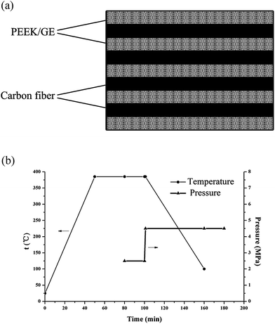 |
| | Fig. 1 (a) Schematic representation of the lay-up stacking sequence of the PEEK/GE/CF laminates. (b) Consolidation process used for laminate manufacturing. | |
2.3. Characterization
2.3.1. Morphological analysis. Scanning electron microscopy (SEM) (JSM-6700F, JEOL, Japan) was used to investigate the fracture surfaces and worn surfaces of the obtained composites, after being coated in a thin gold layer.
2.3.2. Thermal conductivity measurements. The thermal conductivity of each composite was measured by a TC3000 thermal conductivity meter (Xi'an Xiatech Electronics Co., Ltd, China), based on the transient line source technique.
2.3.3. Friction and wear tests. A universal tribotester (MVF-1A, Jinan Hengxu Testing Machine Technology Co. Ltd., China) was used to evaluate the friction behavior of the composites. Sliding was performed under ambient conditions for 1 h at a sliding speed of 0.278 m s−1 and under a load of 50 N. Before each test, the plain carbon steel ring and samples were cleaned with acetone. The specific wear rate was calculated by using the equation:
where Δm is the mass loss; ρ is the density of the composites; Fn is the applied load; L is the sliding distance.
2.3.4. Differential scanning calorimetry. The melt and crystallization behavior of each sample was determined using differential scanning calorimetry (DSC, Mettler-Toledo, USA). The experiments were performed in a nitrogen atmosphere using ∼10 mg of the sample sealed in aluminum pans. Prior to the cooling and heating scans, the samples were held at 380 °C for 5 min to remove the thermal history of the materials. All these steps were performed at heating and cooling rates of 10 °C min−1.
2.3.5. Thermogravimetric analysis. The thermal stability of the composites was determined by thermogravimetric analysis (TGA) (Q500, TA, USA). The samples were heated from 30 to 800 °C at a heating rate of 20 °C min−1. Experiments were carried out on samples with an average mass of 120 mg, and samples were longitudinal cutting from central of the composites. Test specimens were cut by precision saw (SYJ-200, Shenyang kejing automation equipment Co., Ltd, China).
2.3.6. Tensile and flexural tests. The tensile and flexural properties of the laminates were measured with a mechanical tester (3365, INSTRON, USA) at room temperature and 50% relative humidity. Tensile and flexural specimens were employed according to ASTM D3039 and ASTM D790 standards. All the specimens were conditioned for 24 h before the measurements. The data reported were the results for 5 specimens.
3. Results and discussion
3.1. Morphological analysis
To assess the morphology and state of GE dispersion in the fabricated laminates, cross-section of PEEK/0.7 wt% GE/CF laminates were examined by SEM. The micrograph in Fig. 2a shows an image of the PEEK/0.7 wt% GE/CF laminates, which exhibits a good degree of fiber impregnation. The PEEK matrix permeates into the carbon fiber tows and uniformly coated them. It indicates a good fiber-matrix interfacial adhesion. In Fig. 2b, the GE are uniformly distributed in matrix-rich regions, and wrapped by PEEK matrix well. It indicates a larger effective contact area and stronger PEEK–GE interfacial adhesion can result in better fiber impregnation. The dashed circle in Fig. 2a and b shows the distribution of graphene in the PEEK.
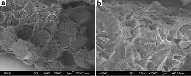 |
| | Fig. 2 Cross-sectional SEM images of PEEK/0.7 wt% GE/CF laminates (a) and (b), the dashed circle shows the distribution of graphene in the PEEK. | |
3.2. Thermal conductivity measurements
The relationship between the thermal conductivities of the PEEK/GE/CF laminates according to the increased amount of GE content is shown in Fig. 3. The thermal conductivity of neat PEEK resin was about 0.23 W m−1 K−1.32 However, the thermal conductivity of the PEEK/CF composites is 0.2449 W m−1 K−1; this improvement in thermal conductivity is mainly ascribed to addition of the GE. The thermal conductivity of the laminates is found to rise with increasing GE content, and it sharply improves at 0.7 wt% GE contents. It can be explained that GE as a heat conductive bridge, 0.7 wt% GE additives is the critical content, above which a continuous connected network formed throughout the PEEK matrix. In addition, the thermal conductivity of the PEEK/GE/CF laminates is 53.7% (0.3763 W m−1 K−1) higher than that of the PEEK/CF laminates at 1.0 wt% GE additive. This increase is because graphene possesses extremely high thermal conductivity, and the dispersion of graphene into the matrix would have significantly enhanced phonon diffusion in the laminates, accordingly increasing their thermal conductivity.
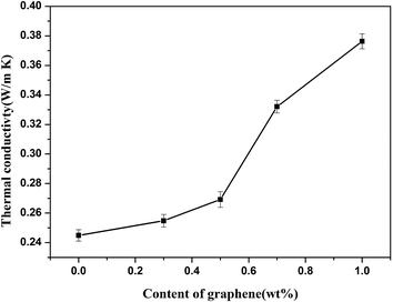 |
| | Fig. 3 Thermal conductivity of PEEK/GE/CF laminates with different contents of graphene. | |
3.3. Friction behaviors
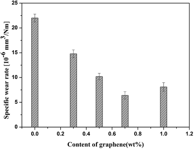
Fig. 4a shows the evolution of the friction coefficients of PEEK/CF and PEEK/GE/CF laminates as a function of sliding time. The incorporation of GE could obviously reduce the friction coefficient of the composites. Moreover, it is worth to note that the friction coefficient is the lowest at 0.7 wt% GE additive. Fig. 4b presents the mean friction coefficients of ternary mixture composites with different contents of GE compared to the PEEK/CF composites in the same applied conditions. According to Fig. 4b, the mean friction coefficient of the laminates is decrease obviously by incorporating of GE. The variation of specific wear rates of the composites with different GE content is shown in Fig. 5. After incorporating 0.7 wt% GE, the wear resistance of the composites was improved significantly and exhibits the lowest specific wear rate, and it was decreased by 70.9% compared with those of PEEK/CF laminates. It should be explained that the formation of a uniform transfer film in the presence of GE, which had a high strength and excellent wear resistance, can carry the most parts of load applied on the sliding surface. Another possible reason for the downward trend in the friction coefficient and specific wear rate could be that the graphene removed the heat generated in the sliding surface and thereby improved the friction reduction abilities of the composites. Further inclusion of the GE results in moderate decreases in the wear resistance of the composites. It was ascribed to a slightly aggregation of GE in the PEEK matrix.
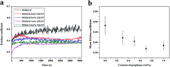 |
| | Fig. 4 (a) Evolutions of friction coefficients of PEEK/CF and PEEK/GE/CF laminates as a function of sliding time; (b) mean friction coefficients of laminates as a function of graphene content. | |
 |
| | Fig. 5 Wear rates of PEEK/GE/CF laminates with different contents of graphene. | |
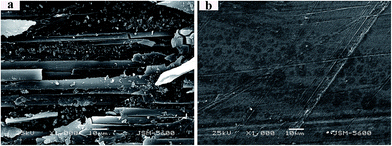
The morphologies of the worn surfaces of PEEK/CF and PEEK/0.7 wt% GE/CF laminates sliding under dry friction are shown in Fig. 6. The worn surface of the PEEK/CF laminates is characterized by serious plastic deformation and the accumulation of wear debris around the carbon fibers, even carbon fibers are fractured, as it can be observed at Fig. 6a. It implies that the PEEK/CF laminates is dominated by severe abrasive wear and fatigue wear. However, the worn surfaces of the PEEK/0.7 wt% GE/CF laminates (Fig. 6b) only exhibits mild scuffing, where even almost no signs of plastic deformation and furrows are detected due to the reinforcement effect of GE.
 |
| | Fig. 6 SEM micrographs of the worn surface of (a) unfilled and (b) 0.7 wt% graphene filled PEEK/CF laminates. | |
3.4. Differential scanning calorimetry
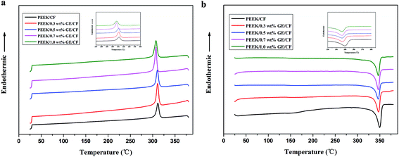
The thermal behavior of the PEEK/GE/CF laminates with various GE contents was studied by DSC measurements in comparison with PEEK/CF laminates. The melting and cooling curves are shown in Fig. 7, and the calorimetric parameters derived from thermograms are collected in Table 2. The inclusion of GE gradually decreases the crystallization temperature from 311.63 °C for PEEK/CF laminates to 307.33 °C for PEEK/1.0 wt% GE/CF laminates (see Table 2), suggesting that rigid GE does not act as nucleating in the PEEK/CF laminates. In this case, GE can slightly retard the mobility of PEEK matrix chain segments during crystallization as compared with homogeneous crystallization of PEEK and thereby postpone the overall crystallization process. Moreover, it can be seen that the melting temperature of the composites shows small changes with the addition of the GE. In addition, the degree of crystallinity of the PEEK/GE/CF laminates drops slightly in comparison to that of PEEK/CF laminates. It can be ascribed to the present of GE inhibited crystallization and lead to the formation of smaller and imperfect crystals.
 |
| | Fig. 7 DSC cooling curves (a) and DSC heating curves (b) for PEEK/CF and PEEK/GE/CF laminates. | |
Table 2 Thermal properties of PEEK/CF and PEEK/GE/CF laminatesa
| Sample |
Tm (°C) |
Tc (°C) |
Xm (%) |
Ti (°C) |
T10 (°C) |
T20 (°C) |
| Tm and Tc are the melting and crystallization temperatures, respectively. Xm correspond to the melting crystallinity. Ti, T10 and T20 correspond to the temperature at 2 wt%, 10 wt% and 20 wt% losses, respectively. |
| PEEK/CF |
350.03 |
311.63 |
39.18 |
583.63 |
598.76 |
607.94 |
| PEEK/0.3 wt%GE/CF |
347.19 |
311.14 |
36.87 |
584.30 |
599.79 |
609.87 |
| PEEK/0.5 wt%GE/CF |
346.46 |
310.66 |
36.59 |
584.32 |
600.15 |
611.29 |
| PEEK/0.7 wt%GE/CF |
346.54 |
307.38 |
36.43 |
584.99 |
600.37 |
612.06 |
| PEEK/1.0 wt%GE/CF |
346.46 |
307.33 |
35.77 |
587.42 |
602.07 |
615.69 |
3.5. Thermogravimetric analysis
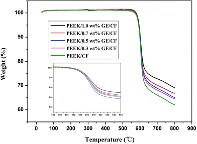
TGA measurement was carried out to evaluate the effect of the GE on the stability of the PEEK/CF laminates, and the corresponding thermogravimetric curves are shown in Fig. 8. The initial degradation temperature at 2 wt% loss (Ti) and the temperature at 10 wt% loss (T10) and 20 wt% loss (T20) for PEEK/CF laminates and PEEK/GE/CF laminates are tabulated in Table 2. It can be observed that the thermal stability of PEEK/CF laminates increases with the addition of GE. The Ti for the PEEK/CF laminates is 583.63 °C, and the Ti for the PEEK/1.0 wt% GE/CF laminates is increases to 587.42 °C, and the T20 is increases from 607.94 °C to 615.69 °C. Therefore, the increase in thermal stability of the laminates could be ascribed to strong interaction between the PEEK matrix and the GE. The strong interaction between the filler and the matrix hindered the segmental motion of polymer chains and restricted thermal mobility of PEEK chains near graphene surface.29 In addition, significantly enhanced thermal conductivity of the laminates can increase the thermal stability of the laminates.
 |
| | Fig. 8 TGA thermogram of the PEEK/CF and PEEK/GE/CF laminates. | |
3.6. Mechanical properties of PEEK/GE/CF laminates
The mechanical properties of particulate composites are strongly influenced by many parameters, including particle shape, particle size, particle distribution, filler loading concentration, microstructure, and interfacial interaction between the particles and the matrix.33 The representative tensile and flexural properties of the PEEK/GE/CF laminates are shown in Fig. 9. The tensile strength of the PEEK/CF laminates is 265.7 MPa and similar with graphene/PEEK/CF laminates. The incorporation of different content of graphene lead to a slight increase in the Young's modulus of PEEK/CF laminates (Fig. 9a). It can be ascribed that the tensile strength and modulus are mainly dominated by the fiber reinforcement. However, experimental data in Fig. 9b reveal improvements in the flexural strength and flexural modulus with increasing GE content. The flexural strength of the laminates increases from 256.39 MPa for PEEK/CF laminates to 269.27 MPa for 1.0 wt% GE reinforced PEEK/CF laminates. The remarkable increase in the flexural modulus with addition of the graphene is attributed to the reinforcement effect of graphene in the z-direction, since the flexural properties are mainly matrix-dominated.34
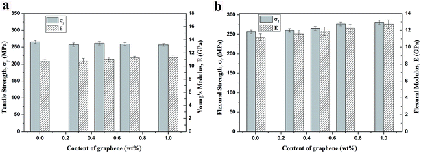 |
| | Fig. 9 Mechanical properties of PEEK/CF and PEEK/GE/CF laminates: (a) tensile strength and Young's modulus; (b) flexural strength and modulus. | |
4. Conclusions
In the present work, a hot pressing technique was used to fabricate PEEK/graphene/carbon fiber laminates with different graphene contents. The introduction of graphene to the PEEK improved its thermal conductivity, which was attributed to the remarkably high thermal conductivity of the graphene and increased phonon diffusion. Moreover, the excellent self-lubrication property of graphene decreased the friction coefficients and the specific wear rates of the laminates. The PEEK/GE/CF laminates also showed high mechanical properties and high thermal stability. Based on the experimental results of the obtained laminates and consideration of the cost of production, the optimum content of GE can be 0.7 wt%. In other words, the PEEK/0.7 wt% GE/CF laminates exhibited good overall performance. Therefore, this new advanced multifunctional material is expected to be suited to an extensive range of applications.
Acknowledgements
The authors acknowledge the Jilin Province Major Science and Technology Achievements Transformation Project of China (11ZDZH003) and Jilin Province Science and Technology Development Project of China (20130204031GX) for financial support.
References
- Y. Hwang, M. Kim and J. Kim, Composites, Part A, 2013, 55, 195–202 CrossRef CAS PubMed.
- L. C. Sim, S. R. Ramanan, H. Ismail, K. N. Seetharamu and T. J. Goh, Thermochim. Acta, 2005, 430, 155–165 CrossRef CAS PubMed.
- W. L. Song, L. M. Veca, C. Y. Kong, S. Ghose, J. W. Connell, P. Wang, L. Cao, Y. Lin, M. J. Meziani, H. J. Qian, G. E. LeCroy and Y. P. Sun, Polymer, 2012, 53, 3910–3916 CrossRef CAS PubMed.
- K. K. Ho, M. C. Hsiao, T. Y. Chou, C. C. M. Ma, X. F. Xie, J. C. Chiang, S. H. Yang and L. H. Chang, Polym. Int., 2013, 62, 966–973 CrossRef CAS PubMed.
- S. Kim and L. T. Drza, Sol. Energy Mater. Sol. Cells, 2009, 93, 136–142 CrossRef CAS PubMed.
- J. A. King, D. R. Klimek, I. Miskioglu and G. M. Odegard, J. Appl. Polym. Sci., 2013, 128, 4217–4223 CrossRef CAS PubMed.
- T. Ramanathan, A. A. Abdala, S. Stankovich, D. A. Dikin, M. Herrera-Alonso, R. D. Piner, D. H. Adamson, H. C. Schniepp, X. Chen, R. S. Ruoff, S. T. Nguyen, I. A. Aksay, R. K. Prud'Homme and L. C. Brinson, Nat. Nanotechnol., 2008, 3, 327–331 CrossRef CAS PubMed.
- M. J. Allen, V. C. Tung and R. B. Kaner, Chem. Rev., 2010, 110, 132–145 CrossRef CAS PubMed.
- A. K. Geim, Science, 2009, 324, 1530–1534 CrossRef CAS PubMed.
- A. A. Balandin, S. Ghosh, W. Bao, I. Calizo, D. Teweldebrhan, F. Miao and C. N. Lau, Nano Lett., 2008, 8, 902–907 CrossRef CAS PubMed.
- S. Chatterjee, J. W. Wang, W. S. Kuo, N. H. Tai, C. Salzmann, W. L. Li, R. Hollertz, F. A. Nuesch and B. T. T. Chu, Chem. Phys. Lett., 2012, 531, 6–10 CrossRef CAS PubMed.
- Y. Z. Hu, J. F. Shen, N. Li, H. W. Ma, M. Shi, B. Yan, W. S. Huang, W. B. Wang and M. X. Ye, Compos. Sci. Technol., 2010, 70, 2176–2182 CrossRef CAS PubMed.
- H. Fukushima, L. T. Drzal, B. P. Rook and M. J. Rich, J. Therm. Anal. Calorim., 2006, 85, 235–238 CrossRef CAS.
- A. P. Yu, P. Ramesh, M. E. Itkis, E. Bekyarova and R. C. Haddon, J. Phys. Chem. C, 2007, 111, 7565–7569 CAS.
- S. Araby, Q. S. Meng, L. Q. Zhang, H. L. Kang, P. Majewski, Y. H. Tang and J. Ma, Polymer, 2014, 55, 201–210 CrossRef CAS PubMed.
- S. Araby, L. Q. Zhang, H. C. Kuan, J. B. Dai, P. Majewski and J. Ma, Polymer, 2013, 54, 3663–3670 CrossRef CAS PubMed.
- S. P. Ju, T. J. Haung, C. H. Liao and J. W. Chang, Polymer, 2013, 54, 4702–4709 CrossRef CAS PubMed.
- P. G. Song, Z. H. Cao, Y. Z. Cai, L. P. Zhao, Z. P. Fang and S. Y. Fu, Polymer, 2011, 52, 4001–4010 CrossRef CAS PubMed.
- Z. A. Ghaleb, M. Mariatti and Z. M. Ariff, Composites, Part A, 2014, 58, 77–83 CrossRef CAS PubMed.
- X. Wang, L. Song, W. Pornwannchai, Y. Hu and B. Kandola, Composites, Part A, 2013, 53, 88–96 CrossRef CAS PubMed.
- G. N. Ren, Z. Z. Zhang, X. T. Zhu, B. Ge, F. Guo, X. H. Men and W. M. Liu, Composites, Part A, 2013, 49, 157–164 CrossRef CAS PubMed.
- M. Fang, K. G. Wang, H. B. Lu, Y. L. Yang and S. Nutt, J. Mater. Chem., 2009, 19, 7098–7105 RSC.
- S. Han and B. C. Chun, Composites, Part A, 2014, 58, 65–72 CrossRef CAS PubMed.
- W. F. Ji, K. C. Chang, M. C. Lai, C. W. Li, S. C. Hsu, T. L. Chuang, J. M. Yeh and W. R. Liu, Composites, Part A, 2014, 65, 108–114 CrossRef CAS PubMed.
- J. Dong, C. Q. Yin, X. Zhao, Y. Z. Li and Q. H. Zhang, Polymer, 2013, 54, 6415–6424 CrossRef CAS PubMed.
- G. B. Huang, S. Q. Wang, P. A. Song, C. L. Wu, S. Q. Chen and X. Wang, Composites, Part A, 2014, 59, 18–25 CrossRef CAS PubMed.
- Y. W. Cao, J. C. Feng and P. Y. Wu, Carbon, 2010, 48, 3834–3839 CrossRef CAS PubMed.
- H. Kim and C. W. Macosko, Polymer, 2009, 50, 3797–3809 CrossRef CAS PubMed.
- L. L. Yang, S. L. Zhang, Z. Chen, Y. L. Guo, J. S. Luan, Z. Geng and G. B. Wang, J. Mater. Sci., 2014, 49, 2372–2382 CrossRef CAS.
- D. J. Gan, S. Q. Lu, C. S. Song and Z. J. Wang, Mater. Lett., 2001, 48, 299–302 CrossRef CAS.
- H. J. Song, N. Li, Y. J. Li, C. Y. Min and Z. Wang, J. Mater. Sci., 2012, 47, 6436–6443 CrossRef CAS PubMed.
- A. M. Diez-Pascual, M. Naffakh, J. M. Gonzalez-Dominguez, A. Anson, Y. Martinez-Rubi, M. T. Martinez, B. Simard and M. A. Gomez, Carbon, 2010, 48, 3500–3511 CrossRef CAS PubMed.
- R. K. Goyal, Y. S. Negi and A. N. Tiwari, Eur. Polym. J., 2005, 41, 2034–2044 CrossRef CAS PubMed.
- A. M. Díez-Pascual, B. Ashrafi, M. Naffakh, J. M. González-Domínguez, A. Johnston, B. Simard, M. T. Martínez and M. A. Gómez-Fatou, Carbon, 2011, 49, 2817–2833 CrossRef PubMed.
|
| This journal is © The Royal Society of Chemistry 2015 |
Click here to see how this site uses Cookies. View our privacy policy here. 


