Fast diffusion supercapacitors via an ultra-high pore volume of crumpled 3D structure reduced graphene oxide activation

Keunsik Leeab, Doyoung Kimac, Yeoheung Yoona, Junghee Yangb, Ho-Gyeong Yund, In-Kyu Youd and Hyoyoung Lee*abc
aCentre for Integrated Nanostructure Physics (CINAP), Institute of Basic Science (IBS), Sungkyunkwan University, 2066 Seoburo, Jangan-gu, Suwon 440-746, Republic of Korea. E-mail: hyoyoung@skku.edu
bDepartment of Chemistry, Sungkyunkwan University, 2066 Seoburo, Jangan-gu, Suwon 440-746, Republic of Korea
cDepartment of Energy Science, Sungkyunkwan University, 2066 Seoburo, Jangan-gu, Suwon 440-746, Republic of Korea
dInformation & Communications Core Technology Research Laboratory, Electronics and Telecommunication Research Institute (ETRI), Daejeon 305-700, Republic of Korea

Received 30th May 2015 , Accepted 6th July 2015

First published on 6th July 2015


Abstract

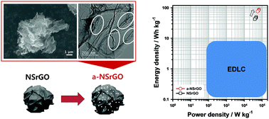
In order to obtain a high performance supercapacitor, there are several factors that must be achieved including a high specific surface area (SSA), high electrical conductivity, and a high diffusion rate of the electrolyte due to an appropriate pore volume. Herein, we report a high performance supercapacitor using activated non-stacked reduced graphene oxide (a-NSrGO) that has a high SSA (up to 999.75 m2 g−1) with intrinsic high graphene conductivity (1202 S m−1) and fast diffusion of the electrolyte. Due to a high total pore volume (5.03 cm3 g−1) and a wide pore size distribution from macro- to micropores (main pore width: 0.61 – 0.71 nm) in the a-NSrGO sheets, the as-prepared a-NSrGO electrode shows high specific capacitance (105.26 F g−1) and a short relaxation time (τ0 = 1.5 s) in a propylene carbonate (PC)-based organic electrolyte. A maximum energy density of 91.13 W h kg−1 and a power density of 66[thin space (1/6-em)]684.73 W kg−1 were estimated in a fully packaged coin cell. The high performance of the a-NSrGO supercapacitors is attributed to their specific appearance and enlarged pore distribution with high SSA.


1. Introduction

Graphene, a 2D sp2-hybridized carbon sheet with one atom thickness, has attracted increasing attention because of its unique structure and properties.1,2 Furthermore, chemically-exfoliated graphene made via Hummer’s method, i.e., graphene oxide (GO), can be produced in large quantities. GO, which contains oxygen groups, is a non-conductive material due to its lack of double bonds that possess conjugated pi electrons; however, reduced graphene oxide (rGO), which can be made by thermal reduction or chemical reduction using hydriodic acid (HI),3 has an enhanced high electrical conductivity. Its high theoretical surface area (2630 m2 g−1) and high electrical conductivity make it particularly attractive as a material for energy storage systems.4,5 These properties suggest that graphene can be used to replace existing materials, including activated carbons that are non-conductive, in conventional applications such as supercapacitors.6 Thus, the use of conductive rGO flakes is expected to be useful in commercially available supercapacitors.

Supercapacitors (or ultracapacitors) that form a double layer of electrolyte ions on the surface of conductive electrodes are considered to be a main contender for energy storage due to their high power performance, long life cycles, and low maintenance costs.7,8 Graphene is an obvious material choice for this application due its high surface area and high conductivity. Currently, graphene-based electrochemical double layer capacitor (EDLC) prototypes lead the field in capacitance, energy density, and power density because of their high electrical conductivity, accessible and defined pore structure, and low equivalent series resistance (ESR).4 However, although numerous studies have detailed the use of graphene nanosheets in supercapacitors, real device applications9 that are scalable are still in progress; many obstacles remain that still need to be overcome. To enhance the capacitive effect for a supercapacitor, several factors, including the electrical conductivity and specific surface area (SSA), have been considered. The use of graphene flakes is contrary to the use of the bulk amorphous sp3 carbon materials (e.g., activated carbons (ACs)), even when these materials have a high SSA.10 Therefore, a solution is required to provide materials with both high SSA and high electrical conductivity. In spite of efforts to increase the SSA of graphene flakes, however, there are still problems such as re-stacking or aggregation of the graphene flakes. To avoid these problems, composite materials with graphene flakes have been used to generate pseudo-capacitance causing redox reactions. However, these materials lack capacitance retention and have a low rate performance due to their demand for a redox reaction.

Recently, controlling the pore volume of graphene supercapacitor electrodes has been one of the most effective and efficient factors for enabling a fast charging/discharging diffusion performance in supercapacitors, which utilizes narrowly controlled sub-nanopores.11–13 For example, materials with only a high SSA and no control over the pore distribution are not suitable for EDLC supercapacitors, which require fast charging and discharging via fast diffusion pathways for the electrolyte. However, until now, although graphene flakes activated with KOH have been known to have high SSAs, the failure to control the pore volume of the 3D graphene electrodes has yielded materials that are insufficient, especially for EDLC supercapacitors. Therefore, in order to obtain good EDLC supercapacitors, a material must have a high SSA and electrical conductivity, while also maintaining a high pore volume in the 3D graphene flake electrodes in order to allow the electrolyte to diffuse easily.

To solve the critical problems facing EDLC supercapacitors, we report on activated non-stacked reduced graphene oxide (a-NSrGO) electrodes that have high conductivity and a high SSA, with a wide pore distribution (from macro- to micro-pores) for a best-fit energy storage performance. These materials have been carefully designed to introduce the non-stacked rGO 3D nanostructure (to maintain a high pore volume and high SSA) and also to introduce KOH-etching of the graphene flakes (to give a high SSA and many diffusion pathways for the electrolyte). The strategy for the synthesis of a-NSrGO is displayed in Fig. 1. First, we synthesized graphene oxide (GO) by a modified Hummer’s method. Then, the non-stacked graphene oxide (NSGO) was prepared via an anti-solvent method using ethanol and hexane, which we developed previously.14 Briefly, the GO sheets were dispersed in ethanol (1 mg mL−1) to allow the GO to be fully exfoliated through strong homogenization. After pouring the non-polar hexane solvent, the resulting precipitates of the non-stacked GO (NSGO) sheets were fully dried using a rotary evaporator. The NSGO was then reduced to make NSrGO through a conventional thermal reduction process. To make a-NSrGO, the NSrGO was then placed in a 7 M KOH solution, followed by filtration and drying. The resulting mixture was put in a tube furnace under the flow of an inert gas at 100 sccm and heated to 800 °C for 1 h. Finally, a-NSrGO was obtained after washing the unreacted KOH, and many types of salt and metal ions, with pure water until the pH reached 7. The chemical reaction of the activation process with KOH has already been suggested: 6KOH + C ↔ 2K + 3H2 + 2K2CO3.15,16


image file: c5ra10246d-f1.tif
Fig. 1 A schematic illustration of the fabrication a-NSrGO. The graphene oxide (GO) is synthesized by a modified Hummer’s method. The non-stacked graphene oxide (NSGO) is prepared from a GO dispersion solution in ethanol (1 mg mL−1) via an anti-solvent method using ethanol and hexane. The NSGO is then reduced by thermal reduction at 1000 °C. Finally the a-NSrGO is fabricated by facile KOH activation at 800 °C. After activation, the sample is washed with pure water to remove any remaining KOH until the pH reaches 7.

2. Experimental methods

2.1 Synthesis of 3D crumpled structure a-NSrGO

Graphene oxide (GO) was prepared by a modified Hummer’s method from natural graphite using sulfuric acid, potassium permanganate, and sodium nitrate.3 We followed our procedure, which has been described previously, to fabricate the NSGO and NSrGO powders.14 For the activation process, 200 mg of NSrGO and 40 mL of a 7 M KOH solution were stirred for 4 h and left to stand for 20 h. The wetted NSrGO was filtered to remove any extra KOH solution, and then the filter cake was dried in a vacuum oven for one day. The dry mixture (200 mg) was placed on a ceramic boat and heated to 800 °C (5 °C min−1) for 1 h in a ceramic tube furnace. After cooling under a vacuum, the sample was repeatedly washed with trice-distilled water until the pH reached 7. The washed sample was again heated to 800 °C (5 °C min−1) for 2 h to fully dehydrate the material. Finally, 80 mg of a-NSrGO was obtained; the yield was about 40%.

2.2 Materials characterization

Structural characterizations were performed using a JEOL JSM-7404F field emission scanning electron microscope operating at 15 kV and a JEOL JEM-2100F transmission electron microscope. The X-ray photoelectron spectroscopy (XPS) measurements were performed on a Thermo VG Microtech ESCA 2000 with a monochromatic Al-Kα X-ray source at 100 W. Raman spectra were recorded on a WITEC alpha300 with a 532 nm excitation wavelength. The Brunauer–Emmett–Teller (BET) theory for specific surface area was measured by a BELSORP-max instrument.

2.3 Fabrication of supercapacitors

Supercapacitors using NSrGO and a-NSrGO were fabricated in a symmetrical two electrode cell with 1 M TEABF4 in a PC organic electrolyte. Al foil was used as the current collector. To prepare the electrode material slurries, 10 wt% polyvinylidene fluoride (PVDF) was added to NSrGO and a-NSrGO as a binder. These slurries were then mixed with a mortar and a ball-mill. The slurries were loaded onto the Al foil by the bar coating method and dried overnight in a vacuum oven at 80 °C. Then, the dried samples were punched with diameter size of 14 mm to fabricate the coin cells. The electrolyte and coin cells were fabricated in a glove box with less than 1 ppm of moisture and oxygen. During coin cell fabrication, Celgard® 3501 was used as a separator between the electrode materials that were loaded into the current collectors. The total mass of the loaded materials in the two electrodes in the coin cell was 2.45 mg for NSrGO and 1.4 mg for a-NSrGO.

2.4 Electrochemical characterization

Cyclic voltammetry, galvanometric charge–discharge curves, and electrochemical impedance spectra over a frequency range of 0.01 Hz to 100 kHz with an amplitude of 10 mV were obtained using a CHI660c electrochemical workstation. The specific capacitance (Cs) was calculated from the galvanometric charge–discharge curves. The following formula was used: Cs = 4I/(mΔVt), where, I is the constant current, m the total mass of both electrodes, and ΔVt is calculated from the slope obtained by fitting a straight line to the discharge curve. The multiplier 4 adjusts the specific capacitance of the cell and the combined mass of the two electrodes to the capacitance and mass of a single electrode.

The evolution of the changes in the real (C′) and imaginary (C′′) parts of the capacitance versus frequency were plotted from the following equations: C′(ω) = −Z′′(ω)/ω|Z (ω)|2 and C′′(ω) = Z′(ω)/ω|Z (ω)|2, where, ω is the pulsation, C′(ω) is the real part of the capacitance, C′′(ω) is the imaginary part of the capacitance, Z(ω) is the electrochemical impedance, and Z′(ω) and Z′′(ω) are the real and imaginary parts of the impedance, respectively, defined as Z2 + Z′′2 = |Z(ω)|2.

The energy density and power density of the electrodes were calculated using the following equations: E = (1/2 × 1000/3600) × CsV)2 and P = (VmaxVdrop)2/4(RESR)m, where Cs (F g−1) is the specific capacitance of the electrode, ΔV (V) is the potential range, E (W h kg−1) is the energy density, P (W kg−1) is the power density, m (g) is the weight of the electrode materials (two electrodes), and the effective series resistance (ESR) is estimated by using the voltage drop at the beginning of the discharge (Vdrop) at a certain constant current Icons (A) with following formula: RESR = Vdrop/(2Icons).

3. Results and discussion

3.1 Morphological and structural characterization

Unlike common GO sheets, our NSGO has a crumpled 3D structure, as shown in Fig. S1. Moreover, the NSrGO and a-NSrGO also maintain their unique structures after thermal reduction and chemical activation processes. To confirm the morphology and nanostructure, the NSrGO and a-NSrGO were characterized by scanning electron microscopy (SEM) and high-resolution transmission electron microscopy (HR-TEM). Fig. 2a and b show SEM images of the crumpled 3D structure of the NSrGO, which is visible even at a high magnification. The HR-TEM images (Fig. 2c and S2a–c) show detailed structural properties with a porous 3D structure. Although the a-NSrGO is treated by a chemical activation process, the SEM images show its unique structure (Fig. 2d and e). In the HR-TEM images shown in Fig. 2f and S2d–f,, the a-NSrGO shows a more distinctive structure, with a crumpled 3D structure and many holes (white circles in the HR-TEM images). The holes on the a-NSrGO clearly indicate etching from the KOH activation process, indicating the presence of meso- and micropores in the porous materials.17 Finally, the a-NSrGO has useful micropores and an advantageous structure for the EDLC mechanisms, indicating easy accessibility for electrolyte ions.
image file: c5ra10246d-f2.tif
Fig. 2 Scanning electron microscopy (SEM) and high-resolution transmission electron microscopy (HR-TEM) images. (a and b): SEM images of NSrGO, (c): HR-TEM image of NSrGO, (d and e): SEM images of a-NSrGO, and (f): HR-TEM image of a-NSrGO. The SEM images of a-NSrGO show that the crumpled 3D structure is maintained after the chemical activation process. The white circles in the HR-TEM image indicate the details of etched holes.

Raman spectroscopy confirmed the synthesis and structural characterization of the a-NSrGO, as shown in Fig. 3a. The D bands of the a-NSrGO appeared at 1349 cm−1. The D band is due to the A1g symmetry mode caused by breathing vibrations of six-member sp2 carbon rings, and only becomes active in the presence of disorder.18 Additionally, the G band of the a-NSrGO was observed at 1583 cm−1. The G band has E2g symmetry, which involves the in-plane bond-stretching motion of pairs of carbon sp2 atoms. This band does not require the presence of six-member rings; it occurs at all sp2 sites as opposed to only those in the rings.19 The integrated D band to G band ratio (ID/IG) slightly increases from 1.02 in NSrGO to 1.20 in a-NSrGO, due to the etching during the activation process (Fig. S3).


image file: c5ra10246d-f3.tif
Fig. 3 (a) Raman spectra of a-NSrGO. (b) X-ray photoelectron microscopy (XPS) C1s peak analysis of a-NSrGO. (c) The N2 sorption isotherm comparison of a-NSrGO with untreated-KOH NSrGO. (d) The pore size distribution for N2 (calculated by the HK method). The red line and blue line indicate micropore (main pore width is 0.61–0.71 nm) and meso- to macropore (larger than micropores) distributions, respectively.

The a-NSrGO was also characterized with X-ray photoelectron spectroscopy in order to determine its structure (Fig. 3b). Primary C1s peaks appear at binding energies of 283.1 eV and 284.5 eV, which are assigned to sp2 carbon bonds (C–C/C[double bond, length as m-dash]C). There are other weak peaks at 285.7 eV, 287.1 eV, and 288.3 eV, which can be identified as the sp3 carbon bonds of the hydroxyl carbon peak (C–O), carbonyl peak (C[double bond, length as m-dash]O), and carboxyl peak (C(O)O), respectively. This indicates that the a-NSrGO is dominated by sp2 conjugated carbon. Furthermore, the C/O ratio was 15.11, which means that the obtained a-NSrGO is mainly composed of carbon atoms. The XPS data of GO and NSrGO are shown in Fig. S4. Due to the presence of oxygen functional groups, GO has a relatively strong peak at 287.1 eV compared to the carbonyl (C[double bond, length as m-dash]O) sp3 carbon bond. However, the NSrGO shows a strong peak (similar to the a-NSrGO), indicating that the NSrGO is composed of carbon atoms and that the a-NSrGO also maintains a carbon-dominant composition despite the KOH activation process.

The porosity was analyzed by N2 gas adsorption–desorption measurements with advanced methods based on the Brunauer–Emmett–Teller (BET) theory for specific surface area, the Barrett–Joyner–Halenda (BJH) method for wide pore distribution, and the Horvath–Kawazoe (HK) method for sub-nanopores (pore width < 1 nm). The HK method is capable of generating model isotherms more efficiently than density functional theory (DFT) to characterize the pore size distribution of microporous materials.20 Fig. 3c shows N2 sorption isotherms with a pronounced hysteresis in the P/P0 range (0.45 to 1.0), indicating the presence of a large number of mesopores the in a-NSrGO.21 The BET calculation implied that the specific surface area of the a-NSrGO is 999.75 m2 g−1, which is higher than that of the KOH-untreated NSrGO (670.65 m2 g−1). In addition, the total pore volume of the a-NSrGO (5.03 cm3 g−1) is also much higher than that of the untreated NSrGO (4.11 cm3 g−1).14 Although the a-NSrGO has a higher total pore volume, it shows a lower volume than the NSrGO at the same weights (Fig. S5). Therefore the a-NSrGO has a high packing density, which means that it can show a higher performance aspect of volumetric capacitance. The plot of the BJH method (blue line in Fig. 3d) shows the wide pore size distribution of the a-NSrGO (from mesopore to macropore), verifying that the maintained crumpled structure of the a-NSrGO can provide effective diffusion pathways for the electrolyte ions to enter the micropores. Furthermore, the HK plot (red line in Fig. 3d) shows the sub-nanopores (micropores) of the a-NSrGO, where the main pore width is between 0.61 and 0.71 nm, and a wide range of pores from mesopores to macropores. The electrical conductivity of the NSrGO and a-NSrGO were also characterized to clearly compare the aspect of material performance. Although the NSrGO and a-NSrGO did not include sub-conductive materials such as carbon black, the NSrGO and a-NSrGO show high electrical conductivities of 1209 S m−1 and 1202 S m−1, respectively. More importantly, the a-NSrGO still maintained its high electrical conductivity after the KOH activation process (Table S1). As a result, the crumpled and etched pores of the a-NSrGO allow for the easy accessibility of electrolyte ions into the macropores, mesopores, and sub-nanopores.

3.2 Electrochemical characterizations

The energy storage effect of various pore size distributions from macro- to micropores of the a-NSrGO was characterized by electrochemical measurements. To prepare a fully packaged coin cell type supercapacitor, a slurry mixture of a-NSrGO and 10 wt% polyvinylidene fluoride (PVDF) (as a binder) was coated on an Al current collector and then completely dried. The cell was fabricated with 1 M tetraethylammonium tetrafluoroborate (TEABF4) in a propylene carbonate (PC) organic electrolyte (the a-NSrGO loading mass of both electrodes was 1.4 mg). Cyclic voltammetry (CV) was first used to determine the capacitive performance of the a-NSrGO (Fig. 4a). The CV curves showed nearly rectangular shapes, even at different scan rates (10–100 mV s−1), indicating ideal supercapacitor performance during the charge–discharge process. Since the wide pore distribution and high SSA of a-NSrGO allow for the fast diffusion of electrolyte ions in the electrode material, the CV curves can maintain their fully-rectangular shape regardless of the scan rate. The specific capacitance of the organic electrolyte (using PC) during discharge at 10 mV s−1 was about 110 F g−1 in the range from 2.5 V to 0 V (i.e., fully discharged). The fully-symmetric galvanostatic charge–discharge curves of the a-NSrGO were observed at current densities of 0.5, 1, 2, and 5 A g−1 (Fig. 4b), verifying the existence of non-faradaic current for just the electric double layer capacitor process. The specific capacitance was 105.26 F g−1, as calculated from the discharge curve at a current density of 0.5 A g−1. Moreover, an IR drop was not observed at the beginning of the discharge curves, suggesting a very low ESR in the a-NSrGO. In addition, the capacitance retention of a-NSrGO at a current density of 5 A g−1 for 10[thin space (1/6-em)]000 cycles is shown in Fig. 4c. The capacitance of 88.4% and the rectangular CV shape were maintained after 10[thin space (1/6-em)]000 cycles.
image file: c5ra10246d-f4.tif
Fig. 4 The electrochemical behaviors of a-NSrGO in a PC-based, 1 M TEABF4 organic electrolyte. (a) Cyclic voltammetry (CV) curves at various scan rates. (b) Galvanostatic charge–discharge curves at various current densities. (c) The cyclic test at a current density of 5 A g−1 for 10[thin space (1/6-em)]000 cycles. The capacitance retention (black triangle line) and the CV curve comparison between the initial cycle (black line) and after 10[thin space (1/6-em)]000 cycles (red line) are shown. (d) Evolution of the real (C′, black circle line) and imaginary (C′′, red circle line) parts of the capacitance of the supercapacitor based on a-NSrGO. A low relaxation time constant (τ0 = 1.5 s) was obtained, despite the fact that a PC-based organic electrolyte was used.

To further confirm the supercapacitor behavior, electrochemical impedance spectroscopy (EIS) measurements were performed in a frequency range from 100 kHz to 10 mHz with an amplitude of 10 mV AC. Fig. S6 shows the Nyquist plot of a-NSrGO. The plot features a vertical curve, indicating the nearly-capacitive performance of the cell. The inset of Fig. S6 is a magnified view of the high frequency range. A Nyquist plot for an electric double layer capacitor is analyzed by looking at the high frequency semicircle, which is caused by the effective series resistance (RS). This is attributed to the ionic conductivity between the electrode materials and electrolyte.22 The a-NSrGO showed very low RS (1.76 Ω), representing the low intrinsic internal resistance of the electrode materials and electrolyte of the supercapacitor cells.23–25 A transition between the RC semicircle and the migration of the electrolyte was observed at a frequency of 146 Hz, which corresponds to a charge transfer resistance (RCT) of 14.83 Ω. The KOH-untreated NSrGO, used as a control, was also characterized by electrochemical measurements for comparison with the a-NSrGO. The electrochemical information of the NSrGO electrode is also shown in Fig. S7 and S8. Although the NSrGO showed a rectangular shape in its CV and a symmetric triangle shape in its galvanostatic charge–discharge curves, similar to a-NSrGO, the a-NSrGO (in comparison with the NSrGO) showed a larger area in its CV curve and a longer discharge time (124.7 s at a current density of 0.5 A g−1) in its galvanostatic charge–discharge curves, indicating that the a-NSrGO exhibited a superior energy storage performance.

To consider the supercapacitor as a whole by using the impedance data, Fig. 4d presents the real part of the capacitance (C′) change (filled circle, black line) and the imaginary part of the capacitance (C′′) change (open circle, red line) versus frequency for a-NSrGO. When the frequency decreases, the C′ significantly increases and then tends to be less frequency-dependent. This is related to the electrode structure and the interface between the electrode and electrolyte.26,27 However, the C′′ curve shows a peak at frequency f0, describing the dielectric relaxation time constant as τ0 = 1/f0 = 1.5 s. τ0 is the minimum time needed to discharge all of the energy from the cell with an efficiency greater than 50%.28 Surprisingly, the a-NSrGO shows a short relaxation time in spite of using a PC-based organic electrolyte, which has a higher viscosity and dielectric constant than an acetonitrile (ACN) electrolyte (activated carbon supercapacitor using PC for τ0 = 48 s and ACN for τ0 = 10 s).26 Commonly, PC electrolyte-based cells are more attractive compared to ACN-based cells due to their stable, non-toxic, and non-volatile properties, especially for commercial applications. However, PC-based cells typically exhibit a slower charging–discharging performance than the ACN-based cells.29 Finally, in Fig. 5a, the rectangular CV area of the a-NSrGO is two times larger than that of the NSrGO. This verifies the fact that the specific capacitance of a-NSrGO is two times higher than NSrGO for energy storage performance in PC-based cells and operates two times faster up to the same capacitance. Furthermore, due to its short relaxation time (1.5 s), the a-NSrGO also demonstrates high power performance.


image file: c5ra10246d-f5.tif
Fig. 5 (a) The rectangular CV curves of a-NSrGO compared with NSrGO (as a control) at a scan rate of 10 mV s−1, showing the higher energy storage performance of a-NSrGO. (b) A Ragone plot of a-NSrGO and NSrGO showing the energy density and power density in a PC-based 1 M TEABF4 organic electrolyte system (opened red circle and black square, respectively). The normalized energy density and power density using the total mass of fully packaged cell (30 wt%) were also indicated (filled red circle and black square, respectively).

In the Ragone plot (Fig. 5b), a maximum energy density of 91.13 W h kg−1 for a-NSrGO was estimated in the fully packaged coin cell, which is much higher than the maximum energy density of 49.31 W h kg−1 for NSrGO. The maximum power density of a-NSrGO (66[thin space (1/6-em)]684.73 W kg−1) was also a higher value than that of NSrGO (46[thin space (1/6-em)]512.73 W kg−1). Supercapacitors contain current collectors, electrolytes, separators, binders, and packing. Because the carbon weight accounts for about 30% of the total mass (30 wt%) of packaged commercial supercapacitors, a factor of 1/3 to 1/4 is frequently used to extrapolate the energy density and power density of the device from the performance of materials.30 To extrapolate the energy density and power density values in the fully packaged cell, we assumed that the carbon material weight accounts for about 30 wt% of the total mass of the packaged commercial cell.21,30 The normalized maximum energy density and power density of a-NSrGO were 30.38 W h kg−1 and 22[thin space (1/6-em)]228.24 W kg−1, respectively. These are much higher than those of the current state-of-the-art commercial supercapacitors.31 As a result, the superior performances of the a-NSrGO, including a high pore volume, SSA, and electrical conductivity, can synthetically provide high power performance as well as high energy storage effects, which were higher than previously reported energy and power density values of crumpled structure carbon materials (Table S2).

4. Conclusions

In summary, we developed activated, porous, and crumpled 3D graphene (a-NSrGO) via simple KOH activation of NSrGO to provide a high SSA and electrical conductivity electrodes that enable fast diffusion of the electrolyte. This combination of properties leads to high power performance in supercapacitors. The a-NSrGO was characterized by Raman and XPS to show the properties of graphene with a crumpled structure, many holes, and a wide pore size distribution (from macropores to micropores). BET showed that the a-NSrGO had a high specific surface area (999.75 m2 g−1) and a high total pore volume (5.03 cm3 g−1). The wide range of pore size distribution is essential for creating energy storage space for electrolyte ions that use narrow micropores for fast diffusion. Furthermore, the a-NSrGO also shows maintenance of high electrical conductivity, 1202 S m−1, leading power performance. As a result, during supercapacitor application with a PC-based organic electrolyte with 1 M TEABF4, the specific capacitance of a-NSrGO was 105.26 F g−1 at a current density of 0.5 A g−1. The EIS results of the supercapacitor cell showed low resistance: RS of 1.76 Ω and RCT of 14.83 Ω. Furthermore, its relaxation time (τ0) was 1.5 s, indicating a very short time for high power performance and a fast diffusion rate of the electrolyte ions. Finally, the maximum energy density of 91.13 W h kg−1 and power density of 66[thin space (1/6-em)]684.73 W kg−1 were estimated in the fully packaged coin cell. Based on these superior properties, the a-NSrGO has a strong potential to be utilized in industrial energy storage applications such as Li-ion batteries, fuel cells, and energy conversion systems.

Acknowledgements

This work was supported by the Institute for Basic Science (IBS-R011-D1) and partially by ISTK (Grant CAP-13-2-ETRI).

References

  1. X. Huang, X. Y. Qi, F. Boey and H. Zhang, Chem. Soc. Rev., 2012, 41, 666–686 RSC.
  2. X. Huang, Z. Y. Yin, S. X. Wu, X. Y. Qi, Q. Y. He, Q. C. Zhang, Q. Y. Yan, F. Boey and H. Zhang, Small, 2011, 7, 1876–1902 CrossRef CAS PubMed.
  3. I. K. Moon, J. Lee, R. S. Ruoff and H. Lee, Nat. Commun., 2010, 1, 73,  DOI:10.1038/ncomms1067.
  4. M. D. Stoller, S. J. Park, Y. W. Zhu, J. H. An and R. S. Ruoff, Nano Lett., 2008, 8, 3498–3502 CrossRef CAS PubMed.
  5. L. L. Zhang, R. Zhou and X. S. Zhao, J. Mater. Chem., 2010, 20, 5983–5992 RSC.
  6. K. S. Novoselov, V. I. Fal’ko, L. Colombo, P. R. Gellert, M. G. Schwab and K. Kim, Nature, 2012, 490, 192–200 CrossRef CAS PubMed.
  7. L. L. Zhang and X. S. Zhao, Chem. Soc. Rev., 2009, 38, 2520–2531 RSC.
  8. P. Simon and Y. Gogotsi, Nat. Mater., 2008, 7, 845–854 CrossRef CAS PubMed.
  9. M. Segal, Nat. Nanotechnol., 2009, 4, 611–613 Search PubMed.
  10. L. Zhang, F. Zhang, X. Yang, G. K. Long, Y. P. Wu, T. F. Zhang, K. Leng, Y. Huang, Y. F. Ma, A. Yu and Y. S. Chen, Sci. Rep., 2013, 3, 1408,  DOI:10.1038/srep01408.
  11. J. Chmiola, C. Largeot, P. L. Taberna, P. Simon and Y. Gogotsi, Angew. Chem., Int. Ed., 2008, 47, 3392–3395 CrossRef CAS PubMed.
  12. J. Chmiola, G. Yushin, Y. Gogotsi, C. Portet, P. Simon and P. L. Taberna, Science, 2006, 313, 1760–1763 CrossRef CAS PubMed.
  13. Y. Gogotsi, A. Nikitin, H. H. Ye, W. Zhou, J. E. Fischer, B. Yi, H. C. Foley and M. W. Barsoum, Nat. Mater., 2003, 2, 591–594 CrossRef CAS PubMed.
  14. Y. Yoon, K. Lee, C. Baik, H. Yoo, M. Min, Y. Park, S. M. Lee and H. Lee, Adv. Mater., 2013, 25, 4437–4444 CrossRef CAS PubMed.
  15. Y. W. Zhu, S. Murali, M. D. Stoller, K. J. Ganesh, W. W. Cai, P. J. Ferreira, A. Pirkle, R. M. Wallace, K. A. Cychosz, M. Thommes, D. Su, E. A. Stach and R. S. Ruoff, Science, 2011, 332, 1537–1541 CrossRef CAS PubMed.
  16. C. Portet, M. A. Lillo-Rodenas, A. Linares-Solano and Y. Gogotsi, Phys. Chem. Chem. Phys., 2009, 11, 4943–4945 RSC.
  17. B. Ding, C. Z. Yuan, L. F. Shen, G. Y. Xu, P. Nie, Q. X. Lai and X. G. Zhang, J. Mater. Chem. A, 2013, 1, 1096–1101 CAS.
  18. S. Niyogi, E. Bekyarova, M. E. Itkis, H. Zhang, K. Shepperd, J. Hicks, M. Sprinkle, C. Berger, C. N. Lau, W. A. Deheer, E. H. Conrad and R. C. Haddon, Nano Lett., 2010, 10, 4061–4066 CrossRef CAS PubMed.
  19. A. C. Ferrari and J. Robertson, Phys. Rev. B: Condens. Matter Mater. Phys., 2000, 61, 14095–14107 CrossRef CAS.
  20. R. J. Dombrowski and C. M. Lastoskie, Stud. Surf. Sci. Catal., 2002, 144, 99–106 CrossRef CAS.
  21. T. Kim, G. Jung, S. Yoo, K. S. Suh and R. S. Ruoff, ACS Nano, 2013, 7, 6899–6905 CrossRef CAS PubMed.
  22. Y. Yoon, K. Lee, S. Kwon, S. Seo, H. Yoo, S. Kim, Y. Shin, Y. Park, D. Kim, J. Y. Choi and H. Lee, ACS Nano, 2014, 8, 4580–4590 CrossRef CAS PubMed.
  23. S. B. Yang, X. L. Wu, C. L. Chen, H. L. Dong, W. P. Hu and X. K. Wang, Chem. Commun., 2012, 48, 2773–2775 RSC.
  24. E. Frackowiak and F. Beguin, Carbon, 2001, 39, 937–950 CrossRef CAS.
  25. C. Portet, P. L. Taberna, P. Simon and C. Laberty-Robert, Electrochim. Acta, 2004, 49, 905–912 CrossRef CAS PubMed.
  26. P. L. Taberna, P. Simon and J. F. Fauvarque, J. Electrochem. Soc., 2003, 150, A292–A300 CrossRef CAS PubMed.
  27. W. P. Si, C. L. Yan, Y. Chen, S. Oswald, L. Y. Han and O. G. Schmidt, Energy Environ. Sci., 2013, 6, 3218–3223 CAS.
  28. D. Pech, M. Brunet, H. Durou, P. H. Huang, V. Mochalin, Y. Gogotsi, P. L. Taberna and P. Simon, Nat. Nanotechnol., 2010, 5, 651–654 CrossRef CAS PubMed.
  29. P. W. Ruch, D. Cericola, A. Foelske, R. Kotz and A. Wokaun, Electrochim. Acta, 2010, 55, 2352–2357 CrossRef CAS PubMed.
  30. Y. Gogotsi and P. Simon, Science, 2011, 334, 917–918 CrossRef CAS PubMed.
  31. A. R. D. Burke, Electrochim. Acta, 2007, 53, 1083–1091 CrossRef CAS PubMed.

Footnote

Electronic supplementary information (ESI) available: Detailed experimental methods, figures relating to the characterization of used GO, NSrGO, and a-NSrGO with electrochemical properties. See DOI: 10.1039/c5ra10246d

This journal is © The Royal Society of Chemistry 2015
Click here to see how this site uses Cookies. View our privacy policy here.