Related magnetic properties of CoFe2O4 cobalt ferrite particles synthesised by the polyol method with NaBH4 and heat treatment: new micro and nanoscale structures

Nguyen Viet Long*abc, Yong Yang*a, Toshiharu Teranishid, Cao Minh Thic, Yanqin Caoa and Masayuki Nogamie
aState Key Laboratory of High Performance Ceramics and Superfine Microstructure, Shanghai Institute of Ceramics, Chinese Academy of Science, 1295, Dingxi Road, Shanghai 200050, China. E-mail: nguyenviet_long@yahoo.com; yangyong@mail.sic.ac.cn; Fax: +86-21-52414219; Tel: +86-21-52414321
bPosts and Telecommunications Institute of Technology, km 10 Nguyen Trai, Hanoi, Vietnam
cHo Chi Minh City University of Technology, 144/24 Dien Bien Phu, Ward-25, Binh Thach, Ho Chi Minh City, Vietnam
dFaculty of Information, Institute for Chemical Research, Kyoto University, Japan
eToyota Physical and Chemical Research Institute, 41-1 Yokomichi Nagakute, 480-1192, Japan

Received 27th May 2015 , Accepted 1st June 2015

First published on 1st June 2015


Abstract

In this contribution, hierarchical CoFe2O4 particles are successfully prepared via a modified polyol elaboration method with NaBH4 and a proposed heat treatment process. Here, new as-prepared CoFe2O4 particles with sizes in the range of 5 μm show highly uniform characteristics in their size, shape and cubic spinel crystal structure according to X-ray diffraction (XRD), whole pattern fitting and Rietveld refinement, X-ray photoelectron spectroscopy (XPS), and scanning electron microscopy (SEM). We discovered that the CoFe2O4 microparticles prepared in the certain size range of 5 μm show exciting configurations of grain and grain boundaries under particle heat treatment at the high temperature 900 °C. Finally, CoFe2O4 ferrite particles with various well-defined micro and nanoscale structures were produced after appropriate heat treatment processes under high temperature, and which have a high coercive field, HC, around 416–888 Oe, and the highest saturation magnetization, MS, of about 74–91 emu g−1 at room temperature (RT) for all of the as-prepared samples measured using a vibrating sample magnetometer (VSM). Here, the magnetic behavior has shown persuasive evidence that the desirable ferrimagnetic properties of CoFe2O4 oxides do not only depend on their size but also on the spinel structure of the CoFe2O4 oxides as well. Finally, the as-prepared CoFe2O4 particles with the formula CoO·Fe2O3 were regarded as the best inverse ferrimagnetic materials with magnetic parameters of HC at 896 Oe, MR/MS squareness around 0.420, and MS around 92 emu g−1 at 20 kOe for the downward part of the hysteresis loop.

1. Introduction

At present, magnetic metal- and oxide-based materials have been of importance for convenient, safe, and clean energy-related applications, and key technologies.1–3 In particular, Fe2O3, Fe3O4, and general formula ferrite compounds such as MO·Fe2O3, MFe2O4 or MIIFeIII2O4 with special micro-, nano-, and nano-to-microscale structures (M = Mn, Co, Ni, Cu or Zn, etc.) are ferrite materials with indispensable applications for our health, life, society, clean energy, green science and technology, etc., to deal with problems and challenges of serious environmental pollution in the 21st century.3–14 It is known that Fe-, Co- and Ni-based ferrite oxides have inverse spinel structures. In comparison with a normal spinel ZnFe2O4 structure, CoFe2O4 spinel structures exhibit a large positive anisotropy constant. The anisotropy and exchange energy gave them magnetic properties between those of soft and hard ferrite.1a–c,3a Among other transition metal oxides, this material has a longitudinal anisotropy, in comparison with a transverse anisotropy. Here, the Curie temperature (TC) of the magnetic materials is influenced by the magnetic status of the material. It possibly causes the ferrimagnetic properties of CoFe2O4 materials to be changed into their superparamagnetic properties.1–3

Although various commercial Fe-, Ni-, and Co-based ferrite powders were produced decades ago, they have a large potential for modern applications in magnetic recording media, various lithium ion batteries (LIBs) and fuel cells (FCs) for the sustainable development of energy and environmental technologies.2,3,15,16,27,32,33 In recent years, Co-, Ni-, and Fe-based ferrites with inexpensive costs have been of commercial importance, such as in microwave components and defense applications.1,2,27 With continuous modifications and improvements to the production processes, scientists have facilely prepared CoFe2O4 or so-called spinel-type CoFe2O4 materials by hydrothermal processes from various Fe and Co precursors. They can carry out the controlled synthesis of Co-, Ni-, and Fe-based ferrite materials by physical and chemical approaches. Additionally, researchers have obtained Fe3O4, CoFe2O4, MnFe2O4, or other modern ferrites with various size ranges of 1–100 nm, 100–1000 nm and 1000–10[thin space (1/6-em)]000 nm (1–10 μm) by feasible synthesis and preparation methods.1–8 Recently, scholars proved that the MS parameter for CoFe2O4 ferrite materials is commonly higher than that of other ferrite materials, such as NiFe2O4, ZnFe2O4, and CuFe2O4, etc., when the content of Co or other transitional metal elements in their structures was varied.17–23 In CoFe2O4 ferrites, e.g. the AB2O4 spinel structure, Fe ions and Co ions refer to tetrahedral and octahedral sites. Therefore, the distribution and oxidation states of Co and Fe inside the oxide particles need to be clarified.

To address the issues of low cost, high performance, and the quality of commercial products in our considerations, CoFe2O4 particle powders must achieve a high homogeneity of size, shape, and structure in a certain particle size range, which is challenging for scientists. In most cases, CoFe2O4 particles possess a wide range of particle sizes and shapes. To address the other aspects, Ni-, Fe-, Co- and CoFe2O4-based materials show interesting properties in terms of the coercivity force (HC), saturation magnetization (MS), and remanent magnetization (Mr), etc., in their magnetic hystereses, with respect to the important effects of magnetic domains and walls.1–5,14,27 Here, most of the results from magnetic nanoparticles with a critical particle size smaller than 100 nm have shown magnetic properties indicative of single magnetic domains under an external magnetic field. There is little research that indicates a comparison between two nanosized and microsized ranges of magnetic materials according to magnetism.

In this research, we report the scientific results of the controlled synthesis of highly homogeneous CoFe2O4 particles using a modified polyol method with NaBH4 with respective heat treatment at 900 °C, and show important evidence for a new structure of CoFe2O4 particles with grain and grain boundary formations in its high inverse level. Here, the reliable ferrimagnetic properties of a high coercivity and saturation magnetization of the grain and grain boundary structures of the CoFe2O4 ferrite materials were discussed, classifying the CoFe2O4 materials as magnetic multidomains. Finally, the Fe and Co oxidation states were found to be 3+ and 2+ inside the best inverse CoFe2O4 oxides.

2. Experimental section

In the controlled synthesis of the CoFe2O4 particles, the starting precursors were prepared as described in previous detailed works involving α-Fe2O3 oxide particles.9–12 Briefly, we paid a lot of attention and spent time developing our preparation processes to the best of our abilities.9–12 In a typical process, 10 mL of EG, 3 mL of 0.0625 M FeCl3 from a FeCl3·6H2O precursor, 1.5 mL of 0.0625 M CoCl2 from a CoCl2·6H2O precursor, 10 mL of 0.375 M PVP, and 0.048 g NaBH4 were used for making Sample 1. In the synthesis procedure, the stock solutions of the Fe and Co precursors were pumped into a reaction flask (250 mL), according to a fixed ratio of 2[thin space (1/6-em)]:[thin space (1/6-em)]1 Fe3+/Co2+ in volume for an exact-controlled synthesis. Similarly, Samples 2 and 3 were prepared with different reaction periods. For the processing requirements, the reaction periods of Samples 1, 2, and 3 were 25, 35, and 45 min, respectively. Then, PVP-CoFe particles were achieved in the resulting black solutions. They were kept at room temperature for some days to collect the black products at the bottom. The clean black products were obtained by removing the PVP on the surfaces of the as-prepared particles using centrifugation, washing and cleaning procedures. The dried powders were re-dispersed into ethanol and dried at 60 °C. To obtain the black-brown oxide products of the CoFe2O4 particles, these black powders were isothermally heated at 900 °C for 1 h with ceramic containers or Pt containers, and in air. Similarly, we prepared various samples for X-ray diffraction (XRD) and scanning electron microscopy (SEM) analysis. Samples 2 and 3 were prepared with different periods but had the same annealing stage. The most typical characterizations of the CoFe2O4 particles were investigated using XRD, SEM, and VSM methods. The X-ray diffraction patterns of the CoFe2O4 particles were recorded in a 2θ range of 5–95° by an X-ray diffractometer (Rigaku-D/max 2550V, 40 kV/40 mA, CuKα radiation at 1.54056 Å). The whole pattern fitting and Rietveld refinement with the phase data involved in the CoFe2O4 oxide microparticles were used for the automated refinement setup for precise determination of the lattice constant and other parameters. Finally, the features of size, shape, and morphology were investigated by field emission (FE)SEM (Magellan-400, FEI, Eindhoven, Netherlands) with SEM and energy dispersive spectroscopy (EDS) methods, and with electron backscatter diffraction (EBSD) in a SIC-CAS, Shanghai, China. The surface chemical bonding was characterized by X-ray photoelectron spectroscopy (XPS) (Escalab 250, Thermo Scientific, Britain). For the XPS analysis, each sample was pre-etched. Thus, the composition of the elements in the cobalt iron ferrite structures was determined. In the XPS analysis, we obtained the information from the initial surfaces and the etched surfaces at 2 kV, 1 μA, 1.0 mm × 1.0 mm for 10 s before testing to remove the surface impurities. All the peaks have been adjusted with taking C285 as the reference. To determine the ferrimagnetic properties of the mentioned as-prepared CoFe2O4, the VSM method was applied for our investigation. We utilized a vibrating sample magnetometer (VSM), Model EV11 at the Institute of Physics (IOP), Academy of Science and Technology (VAST), Ho Chi Minh City, Vietnam, for analyzing the magnetic characteristics of the CoFe2O4 material evaluated at room temperature (RT), about 293 K, over a wide range of applied field from −20 kOe to 20 kOe. Here, the EV11-VSM can reach fields up to 31 kOe at a sample space of 5 mm and 27 kOe in the temperature chamber, with signal noise to be 0.1 μemu, and 0.5 μemu, respectively.

3. Results and discussion

3.1. Crystal structure

In this research, the crystal structures of all of the as-prepared samples of the CoFe2O4 ferrite particles were intensively confirmed during our XRD investigation at room temperature. Fig. 1 shows the most important diffraction peaks of the CoFeO4 ferrite particles (Sample 1) located at (111), (220), (311), (222), (400), (422), (511), (440), (533) and (731), and the possible respective (hkl) indices, which significantly depend on the resolution ability of the diffractometer. The corresponding values of 2θ(°) were estimated at 18.471, 30.396, 35.765, 37.422, 43.481, 53.831, 57.491, 63.134, 74.679 and 90.547 in a 2θ range of 5–95°, respectively. After pattern indexing, we obtained CoFe2O4 with a cubic spinel structure (Fd3m-277: a = b = c = 8.234 Å). All of the parameters are listed in Table 1, which are in agreement with the strongest (311) line of PDF-22-1086 in the Inorganics Data Section. It has the corresponding values of 2θ(°) at 18.288, 30.084, 35.437, 37.057, 43.058, 53.445, 56.973, 62.585, 74.009, and 89.669, in a 2θ range of 5–95°, respectively. Therefore, the parameters were in good agreement with the standard pattern for typical CoFe2O4 ferrite materials. The main diffraction peaks were exactly found in the cubic spinel structure of CoFe2O4 in its crystal growth. In the XRD powder patterns, the CoFe2O4 microstructures with the crystallographic family cF56 and space group Fd3m (no. 227) show lattice constants (a, b, c) equal to 8.3919 Å, 8.3919 Å, and 8.3919 Å in the standard pattern, and with a ratio of c/a = 1 (PDF-22-1086, CoFe2O4 system) calculated using Software of Materials Data JADE and MDI Material data for XRD pattern processing. In the reflections from the lattice constants, the values of d–I or [d(Å)/If(%)] were shown to be 4.7994 Å/11.3%, 2.9382 Å/29.1%, 2.5085 Å/100.0%, 2.4011 Å/10.8%, 2.0796 Å/24.6%, 1.7016 Å/9.70%, 1.6017 Å/34.0%, 1.4714 Å/43.0%, 1.2700 Å/11.6%, and 1.0842 Å/12.5% (Fig. 1a) in comparison with 4.847 Å/10%, 2.968 Å/30%, 2.531 Å/100%, 2.424 Å/8%, 2.099 Å/20%, 1.713 Å/10%, 1.615 Å/30%, 1.483 Å/40%, 1.279 Å/9%, and 1.092 Å/2%, respectively. The strongest outstanding line was revealed to be from the main reflections of the (311) planes. Therefore, the CoFe2O4 particles show high crystallization in the crystal structure of the CoFe2O4 synthesised using a modified polyol method with NaBH4, and heat treatment at about 900 °C to remove all of the kinds of PVP polymer remaining on or covering the surfaces, and possibly existing inside of the as-prepared microparticles.
image file: c5ra10015a-f1.tif
Fig. 1 (a) XRD patterns of the CoFe2O4 particles. (b) The whole pattern fitting and Rietveld refinement of CoFe2O4 oxide microparticles: the calculated pattern (purple); the observed pattern (white); the difference between the calculated pattern and the observed pattern (red).
Table 1 Indexing of the CoFe2O4 with a cubic spinel structure (Fd3m-277: a = b = c = 8.234 Å; α = β = γ = 90°)
2Theta (°) (h k l) d (Å) I (%)
18.471 (1 1 1) 4.7994 11.3
30.396 (2 2 0) 2.9382 29.1
35.765 (3 1 1) 2.5085 100.0
37.422 (2 2 2) 2.4011 10.8
43.481 (4 0 0) 2.0796 24.6
53.831 (4 2 2) 1.7016 9.70
57.491 (5 1 1) 1.6017 34.0
63.134 (4 4 0) 1.4714 43.0
74.679 (5 3 3) 1.2700 11.6
90.547 (7 3 1) 1.0842 12.5


Through the whole pattern fitting (WPF), and with WPF and Rietveld refinement options in Jade 6.5, the WPF of the observed data and Rietveld refinement of the CoFe2O4 crystal structures were performed and are shown in Fig. 1b. In the MDI Jade 6.5 version, PSF, Pearson-VII, pseudo-Voigt, and Gaussian functions were defined. The pseudo-Voigt phase was selected for WPF and Rietveld refinement. The WPF refinement of the XRD pattern was used for quantitative analysis, determination of the precise lattice constants, and structural modeling by refining the atomic parameters.37 Sample 3 was selected for the Rietveld and WPF refinement because of the good shape in its performance. For Sample 3, the results of the lattice constants were obtained by WPF and Rietveld refinement with the profile shape function for all of the phases, i.e. using the pseudo-Voigt polynomial, at λ = 1.54056 Å (Cu/K-α). The lattice constants a, b, and c are equal to 8.37529, 8.37529, 8.37529 Å, respectively, with α, β, and γ all equal to 90°. The value of Rwp was 2.16%, which indicated the so-called residual error function in Jade 6.5, which was minimized by means of non-linear least-squares iterations. Thus, the lattice constants of the CoFe2O4 particles according to the Rietveld analysis were smaller than those of cobalt iron oxide in the PDF-22-1086 standard pattern.

In addition, the surface properties of the prepared CoFe2O4 microparticles were characterized using XPS to determine the existence of the elements and their valence in the prepared inverse spinel oxide structures. Fig. 2, from (A1) to (A4), shows the initial surfaces of Sample 1, and Fig. 2, from (B1) to (B4), shows the pre-etched surfaces of Sample 1 using XPS methods.


image file: c5ra10015a-f2.tif
Fig. 2 (A1–A4): XPS spectra of the CoFe2O4 microparticles with the initial surfaces (Sample 1). (B1–B4): XPS spectra of the CoFe2O4 microparticles with etched surfaces (Sample 1). (C1), (C2), (D1) and (D2): comparison of the initial surfaces and etched surfaces of the CoFe2O4 microparticles by XPS, corresponding to the Fe and Co oxidation states inside the CoFe2O4 oxide. Green lines indicate the background line of the XPS measurements.

In Fig. 2, the C1s peaks and regions show the C285 reference peak and the described adventitious hydrocarbons inside the prepared sample (Sample 1). The O1s peaks and regions were easily visible, and originated from the prepared CoFe2O4 oxides and surrounding environment. The XPS spectra of the primary Fe2p and Co2p core levels of Sample 1 of the prepared CoFe2O4 oxide microparticles are shown in Fig. 2. The Fe2p spectra in Fig. 2(A3, B3, C1, D1) exhibited two peaks at 711.29 and 724 eV, which are identified as the important surface peaks of α-Fe2O3 with the presence of Fe3+ inside Co(II)Fe(III)2O4 oxide. In addition, there are the two common satellite peaks at 719.72 and 733.90 eV that confirmed the Fe oxidation states inside the prepared CoFe2O4 as shown in Fig. 2(A3, C1).38 However, the two above satellite peaks on the surfaces of the CoFe2O4 microparticles were reduced by etching for 10 s. The Co2p spectrum exhibited the two main peaks identified at around 780.76 and 796.43 eV, and with the two satellite peaks identified at around 803.47 and 787.05 eV, respectively. The Co2p1/2 and Co2p3/2 spectra proved the Co2+ valence states. The two main peaks and the two satellite peaks led to the confirmation of the presence of Co2+ inside Co(II)Fe(III)2O4 oxide (Fig. 2: A4, B4, C2 and D2) for the best inverse spinel structures. Of the concerned sample surfaces, Sample 1 has the satellite peaks that are best observed in the XPS spectra. In the prepared CoO·Fe2O3 oxide with the high inverse spinel structure (Fig. 6b), we suggested that the Co and Fe ions occupied Tet- and Oct-cation sites according to the results measured using XPS. Thus, cation distribution at Tet- and Oct-sites to Co2+ and Fe3+ with respect to their oxidation states can lead to a change in the TC and magnetic moment. The highest level of Co2+ content was integrated into the Fe oxide particles for the high inverse CoFe2O4 structure in Fig. 2. It is possible that there is an existence of a very small amount of FeO oxide or Fe oxides in the prepared samples, which will lead to the existence of Fe2+, which cannot be resolved by XRD or XPS and other methods.

3.2. Size and shape

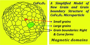
Fig. 3 shows the most typical SEM images of the CoFe2O4 ferrite particles, and the size, shape and morphology characteristics of the CoFe2O4 ferrite particles were also analyzed. We carried out the study in a similar way to the previous works on Fe2O3.3–6 Fortunately, all of the as-prepared samples of the CoFe2O4 particles showed grains and grain boundaries inside the real porous structures after high heat treatment at 900 °C in air (Fig. 3), which shows a certain particle size range of about 1–5 μm for the different samples. The highly homogeneous distributions of size, shape, and morphology of the CoFe2O4 particles were confirmed in the final ferrite products. The highly rough convex and concave surfaces of grains were observed at their interfaces via the grain boundaries. The self-assembly and self-aggregation of the particles were relatively small at the microscale level. Thus, their certain sizes were kept during the particle heat treatment but heavy particle deformation was found. The inner structures changed under high temperatures into various new structures with oxide grains and grain boundaries like the famous polygonal ball models; e.g. C60, with atoms in the nanosized range, is but one such particle that itself indicated some of the best advantages of ball models with typical grains and grain boundaries in the microsized range for the design and optimization of nanomaterials in academic and industrial research (Fig. 3d and e). This is a hierarchical form of material structure. Fig. 3 also illustrates the multidomain structures of the CoFe2O4 microparticles with a spherical shape, at 3.7 μm in size. In these structural and morphological features, the grain boundaries exhibited many right angled and curved forms. From calculations, it was discovered that a particle has about 303 ± 5 CoFe2O4 oxide grains with various right angled or curved grain boundaries between the grains on the surface of the half-section of the surface of the spherical particle (Fig. 3), and about 606 ± 10 CoFe2O4 oxide grains on the whole surface of the spherical particle with a three-dimensional (3D) structure.10–12 There are two kinds of small and large oxide grains, fine grains with smaller sizes in the range of 100 nm, and coarse grains with a larger size range from approximately 100 to 600 nm (0.1–0.6 μm). Therefore, the CoFe2O4 oxide particles were regarded as hierarchical micro/nanostructured oxide materials. All of the as-prepared particles have a microsized range, and every particle has micro/nanoscale structures with grains and grain boundaries. A number of oxide grains, from hundreds to thousands, might be formed during the development of just one CoFe2O4 particle. In various progresses, this strong evidence of grain and grain boundaries of Fe oxide particles was discovered and the high complexity of the surface and structure deformation in Fe2O3 oxide particles intensively explained.10–12
image file: c5ra10015a-f3.tif
Fig. 3 SEM images of the CoFe2O4 particles (a–d). (e) Structural model of the CoFe2O4 microparticles with the grains and grain boundaries as well as the grain arrangement in a spherical model with 606 grains from our results. Scale bars: (a)–(c) 30 μm; (d) 2 μm.

In this context, the oxide grains were considered as single crystal structures with very high stabilities and durabilities in our successful preparation processes. Therefore, they show the most characteristic spherical- and polyhedral-type shapes, typically such as plates, spheres, polyhedral shapes, hexagonal shapes, etc. The samples have different shapes and morphologies, however they show near similar sizes because of the different synthetic periods. It is shown that the final formation of the grain and grain boundary structures of the CoFe2O4 particles was realized. A key point is that it is suggested that the important effects of the particle heat treatment on the formation and grain growth of the stable and durable CoFe2O4 ferrite structures are very necessary to obtain its specific crystal structure. There is no doubt that Pt/CoFe2O4 particles with grains and grain boundaries will become promising magnetic catalytic materials,4,15 and our scientific results have a very large impact in practical applications and technologies for FCs, gas sensors, batteries and supercapacitors. In both theory and practice, the main roles of grain and grain boundary textures are best suited for the simulation, computer modeling of the grain growth, and explanation of the magnetic nanostructures with magnetic domains and walls in the standard measurement of magnetic properties.1–3,26 In the development and formation of micro/nano structures, the grain arrangement and formation of the metal, alloy, or metal oxide in the large microsized range show the same rules as those of atom arrangement and formation of metal nanoparticles and multi-metal oxides in the very small nanosized range. However, we suggest that the above mechanisms and rules of arrangement and formation are completely different. These are still important and challenging topics for scientists in different research fields within science materials such as chemical or physical metallurgy.

Fig. 4 and 5 typically show clear evidence of the chemical analysis of a CoFe2O4 oxide particle of about 6 μm using SEM and EDS methods as detailed in Table 2. The results prove that the Co1−xFe2−yO4 structure has the highest inverse level when in the form of CoFe2O4. For the elements in one Co1−xFe2−yO4 particle, we have found the Fe/Co ratios of apparent concentration, wt%, and atomic% to be 26.4/12.9, 49/24.51, and 28.49/13.51, respectively, which are 2.046512, 1.999184, and 2.108808, respectively, for the best determination with the K-line series. Therefore, the as-prepared structures were achieved as the best formation of the crystal phase of CoFe2O4 oxide, i.e. cobalt iron ferrite with the spinel structure (PDF-22-1086, the CoFe2O4 system). However, the clear evidence for the high C content in the samples found that the C was due to the sample preparation processes in solvents such as ethanol for the SEM measurements.


image file: c5ra10015a-f4.tif
Fig. 4 (a) SEM image of a CoFe2O4 oxide particle with a lot of small and large grains and boundaries. (b) Existence of the elements in one CoFe2O4 oxide particle, measured using SEM-EDS methods.

image file: c5ra10015a-f5.tif
Fig. 5 Chemical analysis of a CoFe2O4 oxide particle in the size range of 6 μm with associated EDS and SEM images of the CoFe2O4 particle; (a) C Kα1,2; (b) Co Lα1-2; (c) O Kα1; (d) Fe Kα1. Scale bars: (a–d) 5 μm.
Table 2 Chemical analysis of CoFe2O4 ferrite using SEM-EDS
Element Line type Apparent concentration k Ratio Wt% Sigma Wt% Atomic%
C K Series 1.15 0.0115 0.11 6.27 16.96
O K Series 23.63 0.07952 0.1 20.22 41.04
Fe K Series 26.4 0.26404 0.19 49 28.49
Co L Series 12.9 0.12899 0.2 24.51 13.51
Total:   100 100


3.3. Magnetism and structure

3.3.1. Ferrimagnetism. In our related investigation of the magnetism of the CoFe2O4 material, the most important measurement parameters, including the MR, MS, HC, HS, S, and S*, etc., were calculated and analyzed from a magnetic hysteresis. Fig. 6a and 7 show the hysteresis loops taken to saturation, which are the two S and S′ points in the MH curves. They typically show the remanent magnetization of M measured at H = 0, the saturation magnetization at maximum M measured in the forward and reverse saturations, the coercive field strength at which M/H changes sign, the squareness parameter (MR/MS), and the maximum energy loss of the hysteresis loop, respectively. For the above parameters, the hysteresis loops indicated the magnetic parameters for the upward parts, downward parts, and average values, respectively (Fig. 7). They also indicated both the ferrimagnetic and ferromagnetic properties. Therefore, CoFe2O4 particles are in the so-called soft magnetic material category. However, there was a clear trend in the magnetic properties of CoFe2O4 ferrite from ferrimagnetism to paramagnetism, then to superparamagnetic properties. Here, MR is shown to be a high value, approximately 39 emu g−1 (−39.681, 38.276, and 38.979 emu g−1). Fig. 6a shows MS to be on average 91 emu g−1 for Sample 1 (91.373, −91.577, and 91.475 emu g−1), corresponding to the proposed inverse CoO·Fe2O3 spinel structure in Fig. 6b, which is one of the highest values that has been found so far for various CoFe2O4 materials, in comparison with recent reports.5–9,14 Here, HC shows a high coercive field strength equal to around 888 Oe (880.60, −895.65, and 888.13 Oe). All of the typical parameters of the magnetic hystereses of the as-prepared CoFe2O4 material are listed in Table 3 for Samples 1, 2, and 3. The ferrimagnetism of the as-prepared CoFe2O4 can be explained using molecular field theory between the two sublattices in the AB2O4 structure between M = MA + MB.1 On the other hand, magnetite Fe3O4 materials with inverted spinel structures have Fe3+ ions located at A sites (tetrahedral A sites or Tet-A) and Fe2+ ions located at B sites (octahedral B sites or Oct-B). We also can express MFe2O4 as Fex+3M1−x+2[Fe2−x3+Mx+2]O4 with respect to x = 0 (normal spinel), typically for M = Cd and Zn, and x = 1 (inversed spinel) for other metal ions.3a It has been proven that Fe2+ ions can be also replaced with Co2+ ions at the B sites of the model of the identified spinel structure.1–3 The unit cell contains 32 O2− ions, 8 metal ions in Tet-A sites, and 16 metal ions in Oct-B sites, for a total number of 56 ions.1a There was a relative distribution of magnetic Fe ions in Tet-A and Oct-B sites when the Co ions were integrated into CoFe2O4. We suggest that increasing the Co content and its integration level into the Fe oxide matrices changes the matrices into CoxFe2O4 (x ≤ 1), and with a further increase of the Co content they change into the CoFe2O4 materials that leads to the change of the (super)paramagnetic properties of the Fe oxide structure, such as the Fe3O4 structure, into the ferrimagnetic properties of the CoFe2O4 structure. We also think that the increased ability to replace Fe ions with Co ions located at the Tet-A site or Oct-B site can lead to the creation of the better CoFe2O4 structure in the formula CoxFeyO4 structure with the highest limit x = 1 and y = 2 from various experiments during careful preparation processes. Conversely, a system of Fe1−xCo2O4 (x ≤ 1) with a change in the Fe content can be prepared using facile preparation processes.25 During our considerations, we proposed that the Co ions have various ways of integrating into the spinel structure and their possible distribution into and occupation of both the tetrahedral and octahedral sites of the spinel structure. So, there are various possibilities for the locations of the Co ions located in a spinel structure, which can be the normal form AtetB2octO4, the inverse form Btet(A,B)octO4, or the random mixed form (BxAy)tet(Ax1By1)octO4 (x + y = 1 or ≤1; x1 + y1 = 2 or ≤2) with perfect growth and crystallization during well-organized heat treatment or sintering. Additionally, there is also the existence of empty sites in the spinel unit cell of CoFe2O4. This has been possibly the main cause of controversy arising because the resolution of some diffractometers is not sufficient in order to obtain the exact determination of the remaining minor crystal phases and Rietveld analysis. These empty sites can lead to very minor crystal phases of CoO, Co3O4 (or CoCo2O4 spinel structure) or FeO, Fe2O3, Fe3O4 (or FeFe2O4 spinel structure) as well as the very minor possible crystal phases of cubic FeCo2O4 ferrite with a spinel structure, and hexagonal ferrites CoFe12O19 with a magnetoplumbite structure27 according to the preparation and heat treatment processes used. They coexist in cobalt iron ferrite with the major phase of CoFe2O4, i.e. AB2O4, which resulted in different results for the paramagnetic or ferromagnetic or ferrimagnetic properties from the hysteresis loops in various works.17–25,27,28 Thus, an extra amount of the Co or Fe precursor will lead to the mixture of many phases including minor phases of Co oxides or Fe oxides inside the major phase of CoFe2O4. Usually, all of the minor phases are ignored because of the difficulty in observation with the resolution of XRD (Fig. 1a). This is the main reason and the way that we can develop oxide-based AB2O4 ferrites with better structures, and with new rare earth AB2O4 ferrites. In comparison with our results, CoFe2O4 ferrites prepared by methods that use oxide precursors will lead to the non-uniform characteristics inside their structures. Additionally, there was a possible case that MFe2O4 powders can also form with a very small amount of a minor amorphous phase in comparison with the major crystal phase.29–35 However, metal cation distribution (metal cation M1: Co2+, Ni2+...) was also considered to correspond to incomplete inversion in the case of M1–Fe2O4 by density functional theory (DFT).35 Thus, the prepared CoFe2O4 material exhibited weak ferromagnetism or ferrimagnetism in magnetic multidomain structures. This possibly leads to the wide range of magnetic properties from superparamagnetism without magnetic hysteresis, paramagnetism or antiferromagnetism, to ferrimagnetism or ferromagnetism.17–23 It turned out that this unique ferrimagnetic characteristic was due to the existence of various magnetic small and large multidomains from the grain and grain boundary configurations of the various as-prepared CoFe2O4 materials during the heat treatment process used.10 At present, this is a concern of researchers in understanding the growth and formation of ferrite materials with grains and grain boundaries as well as their magnetic properties according to the phenomena of magnetic domains and walls.1–3
image file: c5ra10015a-f6.tif
Fig. 6 (a) Magnetic hysteresis of CoFe2O4 (Sample 1). (b) Model of the spinel structure of CoFe2O4.

image file: c5ra10015a-f7.tif
Fig. 7 (a) Magnetic hystereses of CoFe2O4 (Samples 1, 2, and 3). (b) Expanded snapshot of (a).
Table 3 Typical magnetic parameters of the hysteresis loops calculated using the VSM method for the as-prepared weak ferromagnetic or ferrimagnetic CoFe2O4 materials. Symbols: MR: remanent magnetization, MS: saturation magnetization, HC: coercive field, S: squareness (MR/MS), S′: 1 − (MR/HC)(1/slope at HC)
Samples Parameters Unit Upward Downward Average
Sample 1 MR emu g−1 −39.681 38.276 38.979
MS emu g−1 91.373 −91.577 91.475
HC Oe 880.60 −895.65 888.130
S (MR/MS) Constant 0.430 0.420 0.430
S* Constant 0.251 0.246 0.248
Sample 2 MR emu g−1 −22.797 22.781 22.789
MS emu g−1 81.331 −81.412 81.372
HC Oe 505.84 −502.25 504.05
S (MR/MS) Constant 0.280 0.280 0.280
S* Constant 0.118 0.111 0.115
Sample 3 MR emu g−1 −26.205 26.211 26.208
MS emu g−1 74.375 −74.502 74.439
HC Oe 417.87 −415.08 416.48
S (MR/MS) Constant 0.350 0.350 0.350
S* Constant 0.088 0.088 0.088


3.3.2. Magnetic behavior. In line with the common nature of micromagnetism and nanomagnetism, our results had a symmetrical magnetic hysteresis loop, which is considered as the ideal-form ferrimagnetic hysteresis (Fig. 6), indicating a good magnetic ferrite material, whose remanent magnetization shows a positive magnetization (MR) equal to that of the negative magnetization (−MR) in a near symmetrical hysteresis loop. On the other hand, the positive (HC) and negative (−HC) coercive field strength or coercivity at the two upward parts or downward directions of the applied field are nearly the same values according to the magnetic hysteresis. However, some researchers illustrated the saturation magnetization of MFe2O4 nanoparticles in the size ranges of 10 to 20 nm, and found MS to be decreasing in order for MnFe2O4, Fe3O4, CoFe2O4, NiFe2O4, ZnFe2O4 , and to be highest at 86 emu g−1 for MnFe2O4 (16 nm). There are some special cases of superparamagnetic Fe oxide (SPIO) particles,24 and most MFe2O4 materials possibly show high superparamagnetic properties. Sample 1 has values of MS and HC that show the highest saturation magnetization and coercive field in Fig. 7. However, our prepared samples have shown the good ferrimagnetic properties of CoFe2O4 particle powders in a microsized range (5 μm) in comparison with the superparamagnetic properties of MFe2O4 particles of a nanosized range (20 nm) (M = Mn, Fe, Co, and Ni),24 such as MS = 86 emu g−1 for MnFe2O4 nanoparticles 16 nm in size24 as well as the MFe2O4 (M = Mn2+, Fe2+, Co2+, Ni2+) ferrite spinel.29 Fig. 6 and 7 evidently illustrate the narrow hysteresis MH loops, which enable their large potential applications in high frequency devices.1–3,27 The MS values of MnFe2O4 (around 7 nm), CoFe2O4 (9 nm), NiFe2O4 (11 nm), and FeFe2O4 (24 nm) are 23.9, 69.7, 34.2, and 58.6 emu g−1, respectively, while their corresponding theoretical values are 120.8, 71.2, 47.5, and 96.2 emu g−1. For structural considerations, the saturation magnetization MS of the CoFe2O4 particles in the range of 5 μm with grains and grain boundaries looks much higher than that of CoFe2O4 nanoparticles in the size ranges of 25–60 nm and 60–135 nm.24 In this comparison, these results show a difference between the nanosized and microsized ranges of CoFe2O4, and between their micro and nanostructures. The behavior of micromagnetism and nanomagnetism of Fe-based oxides is relatively similar in their magnetic hysteresis loops.34 This can be possibly true among soft and hard ferrimagnetic materials with many modifications in their bulk, film, and particle powders. Fig. 8 illustrates the hierarchical magnetic oxide particles with oxide grains and grain boundaries corresponding to the obtained results in our research. Therefore, their shapes and morphologies can be controlled in various polyhedral and spherical forms. Overall, we reconfirmed that the prime importance and the effects of shape and structure of magnetic alloys and ferrites are also the same as that of the size in micro/nanoscale materials while they have a huge potential for commercial, industrial, academic, military, and space applications.27,36
image file: c5ra10015a-f8.tif
Fig. 8 Models of the hierarchical particles with grains and grain boundaries (A1–A14).

4. Conclusion

In this research, the hierarchical CoFe2O4 ferrite microparticles were made from two constituent mixtures of the FeCl3 and CoCl2 precursors. Here, we aimed to study the synthesis and preparation processes of CoFe2O4 particle powders with a highly homogeneous distribution of particle size and crystalline structures in the as-prepared oxide products. We have tried to achieve the most successful preparation of CoFe2O4 particle powders in our efforts of process optimization with preparation and experimental conditions. They possess a specific grain and grain boundary microstructure, with regard to a high crystallization of ferrimagnetism. It is predicted that it is the high density of the grains and boundaries inside the prepared oxide microparticles that can lead to the high ferrimagnetic properties of the CoFe2O4 microparticles with the main valence states to be +2 for Co, and +3 for Fe. We have presented a new approach for the preparation process of grain and grain boundary textures of the new CoFe2O4 ferrites, and obtained the best ferrimagnetic properties for CoFe2O4 ferrite materials in the range of 5 μm in size. We suggest that there are various spinel structures that are CotetFe2octO4, Fetet(Fe,Co)octO4, and (CoxFey)tet(Fex1Coy1)octO4 (x + y = 1, and x1 + y1 = 2). Here, A and B indicate Fe and Co ions. Therefore, the Co cation distribution in the cobalt iron ferrites reached the highest degree, which is in the level of the best inversion when x = 0 and y = 0 according to the much simpler formula of the Co1−xFe2−yO4 spinel structure. Our preparation process shows a high stability and repetition of CoFe2O4 products. Finally, not only the crystal features of CoFe2O4 particles are clarified but also the importance of the ferrimagnetic properties is discussed for micro/nanoscale structures.

Conflict of interest

The authors declare no conflict of interest.

Acknowledgements

We are grateful for precious support through a Visiting Fellowship for Researchers from Developing Countries (Grant no. 2013FFGB0007) and the China Postdoctoral Science Foundation (no. 2014M551462) in the period of 2013–2015 from the Shanghai Institute of Ceramics, Chinese Academy of Science, Dingxi Road 1295, Shanghai 200050, China.

References

  1. (a) S. Chikazumi, Physics of Ferromagnetism (International Series of Monographs on Physics), Published in the United States, Oxford University Press Inc., New York, 2nd edn, 2009 Search PubMed; (b) A. Goldman, Modern ferrite technology, Springer, Science-Business Media, Inc., 2nd edn, 2006 Search PubMed; (c) S. Hirosawa, J. Magn. Soc. Jpn., 2015, 39, 85–95 CrossRef.
  2. R. M. Cornell and U. Schwertmann, The Iron Oxides: Structure, Properties, Reactions, Occurences and Uses, John Wiley & Sons, Inc., Verlag GmbH&Co. KGaA, Weinheim, 2003 Search PubMed.
  3. (a) K. H. J. Buschow, F. R. de Boer, Physics of Magnetism and Magnetic Materials, Springer, 2003 Search PubMed; (b) J. M. D. Coey, Magnetism and Magnetic Materials, Cambridge Press, 2010 Search PubMed; (c) T. Miyazaki, H. Jin, The Physics of Ferromagnetism, Springer Series in Materials, Science Springer, Verlag, Berlin, Heidelberg, 2012, vol. 158 Search PubMed; (d) Y. Liu, D. J. Sellmyer, D. Shindo, Handbook of Advanced Magnetic Materials, Springer Science, Business Media, Inc. 2006 Search PubMed.
  4. C. Yuan, H. B. Wu, Y. Xie and X. W. Lou, Angew. Chem., Int. Ed., 2014, 53, 1488–1504 CrossRef CAS PubMed.
  5. M. Abbas, M. N. Islam, B. P. Rao, K. E. A. Aitah and C. Kim, Mater. Lett., 2015, 139, 161–164 CrossRef CAS PubMed.
  6. L. Lv, Q. Xu, R. Ding, L. Qi and W. Wang, Mater. Lett., 2013, 111, 35–38 CrossRef CAS PubMed.
  7. N. Dong, F. He, J. Xin, Q. Wang, Z. Lei and S. Su, Mater. Lett., 2015, 141, 238–241 CrossRef CAS PubMed.
  8. L. Khalil, C. Eid, M. Bechelany, N. Abboud, A. Khoury and P. Miele, Mater. Lett., 2015, 140, 27–30 CrossRef CAS PubMed.
  9. D. Zhang, X. Zhang, X. Ni, J. Song, H. Zheng and J. Magn, J. Magn. Magn. Mater., 2006, 305, 68–70 CrossRef CAS PubMed.
  10. N. V. Long, Y. Yang, C. M. Thi, Y. Cao and M. Nogami, Colloids Surf., A, 2014, 456, 184–194 CrossRef PubMed.
  11. N. V. Long, Y. Yang, M. Yuasa, C. M. Thi, Y. Cao, T. Nann and M. Nogami, RSC Adv., 2014, 4, 8250–8255 RSC.
  12. N. V. Long, Y. Yang, M. Yuasa, C. M. Thi, Y. Cao, T. Nann and M. Nogami, RSC Adv., 2014, 4, 6383–6390 RSC.
  13. N. V. Long, Y. Yang, B. T. Hang, Y. Cao, C. M. Thi and M. Nogami, Colloid Polym. Sci., 2015, 293, 49–63 CAS.
  14. R. Iano, Mater. Lett., 2014, 135, 24–26 CrossRef PubMed.
  15. N. V. Long, Y. Yang, C. M. Thi, Y. Cao, N. V. Minh and M. Nogami, Nano Energy, 2013, 2, 636–676 CrossRef PubMed.
  16. A. R. Jha, Rare Earth Materials Properties and Applications, CRC Press, Taylor & Francis Group 6000 Broken Sound Parkway NW, Suite 300, Boca Raton, FL33487–2742, 2014 Search PubMed.
  17. M. Dong, Q. Lin, D. Chen, X. Fu, M. Wang, Q. Wu, X. Chen and S. Li, RSC Adv., 2013, 3, 11628–11633 RSC.
  18. R. Sharma, S. Bansal and S. Singhal, RSC Adv., 2015, 5, 6006–6018 RSC.
  19. Z. Zhang, W. Ren, Y. Wang, J. Yang, Q. Tan, Z. Zhong and F. Su, Nanoscale, 2014, 6, 6805–6811 RSC.
  20. H. Guo, T. Li, W. Chen, L. Liu, X. Yang, Y. Wang and Y. Guo, Nanoscale, 2014, 6, 15168–15174 RSC.
  21. W. Yang, Y. Yu, L. Wang, C. Yang and H. Li, Nanoscale, 2015, 7, 2877–2882 RSC.
  22. D. Primc and D. Makovec, Nanoscale, 2015, 7, 2688–2697 RSC.
  23. N. Lee and T. Hyeon, Chem. Soc. Rev., 2012, 41, 2575–2589 RSC.
  24. (a) J. Mohapatra, A. Mitra, D. Bahadur and M. Aslam, CrystEngComm, 2013, 15, 524–532 RSC; (b) J. Mohapatra, S. Nigam, J. Gupta, A. Mitra, M. Aslam and D. Bahadur, RSC Adv., 2015, 5, 14311–14321 RSC.
  25. L. Ajroudi, N. Mliki, L. Bessais, V. Madigou, S. Villain and C. Leroux, Mater. Res. Bull., 2014, 59, 49–58 CrossRef CAS PubMed.
  26. F. Zasada, J. J. Gryboś, P. Indyka, W. Piskorz, J. Kaczmarczyk and Z. Sojka, J. Phys. Chem. C, 2014, 118, 19085–19097 CAS.
  27. R. C. Pullar, Prog. Mater. Sci., 2012, 57, 1191–1334 CrossRef CAS PubMed.
  28. L. Ajroudi, N. Mliki, L. Bessais, V. Madigou, S. Villain and C. Leroux, Mater. Res. Bull., 2014, 59, 49–58 CrossRef CAS PubMed.
  29. R. Pązik, E. Piasecka, M. Małecka, V. G. Kessler, B. Idzikowski, Z. Śniadecki and R. J. Wiglusz, RSC Adv., 2013, 3, 12230–12243 RSC.
  30. K. V. P. M. Shafi, A. Ulman, X. Yan, N. Yang, C. Estournes, H. White and M. Rafailovich, Langmuir, 2001, 17, 5093–5097 CrossRef CAS.
  31. N. Bao, L. Shen, Y. Wang, P. Padhan and A. Gupta, J. Am. Chem. Soc., 2007, 129, 12374–12375 CrossRef CAS PubMed.
  32. X. Wu, Z. Lu, W. Zhu, Q. Yang, G. Zhang, J. Liu and X. Sun, Nano Energy, 2014, 10, 229–234 CrossRef CAS PubMed.
  33. Y. Xiao, J. Zai, X. Li, Y. Gong, B. Li, Q. Han and X. Qian, Nano Energy, 2014, 6, 51–58 CrossRef CAS PubMed.
  34. H. Zeng, J. Li, Z. L. Wang, J. P. Liu and S. Sun, Nano Lett., 2004, 4, 187–190 CrossRef CAS.
  35. D. Fritsch, H. H. Wills and C. Ederer, Phys. Rev. B: Condens. Matter Mater. Phys., 2012, 86, 014406 CrossRef.
  36. V. G. Harris, Microwave Magnetic Materials, in Handbook of Magnetic Materials, ed. K. H. J. Buschow, 2012, vol. 20, pp. 1–63 Search PubMed.
  37. G. Will, Powder Diffraction, The Rietveld Method and the Two Stage Method to Determine and Refine Crystal Structures from Powder Diffraction Data, Springer-Verlag Berlin Heidelberg, 2006 Search PubMed.
  38. K. Zhang, W. Zuo, Z. Wang, J. Liu, T. Li, B. Wang and Z. Yang, RSC Adv., 2015, 5, 10632–10640 RSC.

Footnote

Electronic supplementary information (ESI) available. See DOI: 10.1039/c5ra10015a

This journal is © The Royal Society of Chemistry 2015
Click here to see how this site uses Cookies. View our privacy policy here.