
Nickel nanocomposites: magnetic and catalytic properties†
C. Castilloa,
K. Seguinb,
P. Aguirrea,
D. Venegas-Yazigicd,
A. D. C. Viegase,
E. Spodine*ac and
V. Paredes-Garcia*bc
aFacultad de Ciencias Químicas y Farmacéuticas, Universidad de Chile, Santiago, Chile
bUniversidad Andres Bello, Departamento de Ciencias Químicas, Santiago, Chile
cCEDENNA, Santiago, Chile. E-mail: vparedes@unab.cl
dFacultad de Química y Biología, Universidad de Santiago de Chile, Santiago, Chile
eInstituto de Física, Universidade Federal do Rio Grande do Sul, Porto Alegre, Brazil
First published on 7th July 2015
Abstract
In this study, we are reporting the synthesis and characterization of nanocomposites obtained from the direct reduction of nickel(II) salts on matrices of polyethylene (Pe) and chitosan (Ch) in the presence of serine under solvothermal conditions. Using different molar ratios between the metal salt (M) and the amino acid (AA), eight nanocomposites were prepared, Ni–Pe1; Ni–Pe2; Ni–Pe3; Ni–Pe4 and Ni–Ch1; Ni–Ch2; Ni–Ch3; Ni–Ch4 (M![[thin space (1/6-em)]](https://www.rsc.org/images/entities/char_2009.gif) :AA = 1:1, (1); 0.5:1, (2); 0.25:1, (3) and 0.125:1, (4)). The synthesized composites were characterized by X-ray powder diffraction techniques; in all the cases, the peaks associated to the matrix (Pe or Ch) and three peaks at 2θ values of 44.5°, 51.9°, 76.4° were identified, which correspond to the Miller indices (111), (200), (220). These indices are characteristic of a face centred cubic Ni0 phase. The SEM images of the composites show that the use of an organic matrix changes the size and distribution of the metallic particles because in all the cases a homogenous dispersion of Ni0-NPs on the matrix surfaces is observed. While the spherical shape observed for isolated Ni0-NPs is retained on the matrices, the size of the metallic particles is smaller than 100 nm with less size variability, as compared with the isolated Ni0-NPs. All the composites have a weak ferromagnetic behaviour with similar hysteresis loops, presenting Hc values ranging from 120 to 226 Oe and reaching saturation at approximately 3 kOe. Preliminary catalytic properties for hydrogen transfer reaction were also investigated, showing that the composites exhibit an important activity in the transformation of acetophenone to 1-phenylethanol.
:AA = 1:1, (1); 0.5:1, (2); 0.25:1, (3) and 0.125:1, (4)). The synthesized composites were characterized by X-ray powder diffraction techniques; in all the cases, the peaks associated to the matrix (Pe or Ch) and three peaks at 2θ values of 44.5°, 51.9°, 76.4° were identified, which correspond to the Miller indices (111), (200), (220). These indices are characteristic of a face centred cubic Ni0 phase. The SEM images of the composites show that the use of an organic matrix changes the size and distribution of the metallic particles because in all the cases a homogenous dispersion of Ni0-NPs on the matrix surfaces is observed. While the spherical shape observed for isolated Ni0-NPs is retained on the matrices, the size of the metallic particles is smaller than 100 nm with less size variability, as compared with the isolated Ni0-NPs. All the composites have a weak ferromagnetic behaviour with similar hysteresis loops, presenting Hc values ranging from 120 to 226 Oe and reaching saturation at approximately 3 kOe. Preliminary catalytic properties for hydrogen transfer reaction were also investigated, showing that the composites exhibit an important activity in the transformation of acetophenone to 1-phenylethanol.
Introduction
Magnetic nanoparticles are widely studied because they exhibit interesting electrical, magnetic and chemical properties, which differ from those observed for bulk materials. Different synthetic techniques controlling the size, shape and morphology of nanoparticles have been reported;1–10 among these the chemical vapour deposition (CVD),2 wet chemistry,3 laser-driven aerosol,4 hydro/solvothermal methods,5,6 and the microemulsion synthetic route have been used extensively.7,8 Metallic nanoparticles are mainly used in the preparation of catalysts, batteries and magnetic materials for data storage.1 In particular, nickel is an important magnetic material that exhibits variable magnetism at room temperature, and the magnetic properties are strongly affected by the morphology, size and shape of nickel nanoparticles.11–15 In addition, nickel nanoparticles have interesting applications in the growth of carbon nanotubes16 and in the catalysis of the reduction reaction of different organic functional groups.17 However, the catalytic properties of nickel nanoparticles have been studied less frequently compared to those of noble metals.18 Literature data report that the nickel nanoparticles have been used as catalysts in the hydrogen transfer reaction to carbonyl groups, and hydrogenation of nitrobenzene; both being reactions of great industrial importance.19,20 The preparation of alcohols from carbonyl compounds has numerous applications in the industrial synthesis of dyes, pharmaceuticals, agrochemicals and biologically active compounds.21 Therefore, the development of new and efficient catalysts for this type of reaction is a great challenge. However, the use of nickel nanoparticles as catalysts requires avoiding their oxidation. Therefore, the metallic nanoparticles have to be supported on different matrices to reach the necessary stability. Nickel nanoparticles supported on different matrices, such as carboxymethyl cellulose,22 hydrocalcite-clay,23 TiO2, Al2O3, SiO2, zeolites/aluminosilicates, chitosan and carbon nanotubes, have been reported,24–29 thus generating new and interesting nickel-based materials. These systems have been studied in relation to not only their role in heterogeneous catalysis, but also for the dependence of their catalytic activity on size, shape and dispersion in the used matrix.30On the other hand, polymeric nanocomposites, which are obtained from nanoparticles and polymeric matrix, are interesting because the chemical nature and the structure of polymers can change the shape and size of the nanoparticles. In addition, the intrinsic characteristic of the matrix should also have influence on the distribution of the nanoparticles in a polymeric matrix. Therefore, considering the relevance and applications of the nickel nanoparticles, in this study, we report the synthesis of nanocomposites obtained from the direct reduction of nickel(II) chloride on matrices of polyethylene (Pe) and chitosan (Ch). Both matrices were chosen considering the chemical differences between them. To evaluate the role of the organic matrices on the obtained products, the synthesized Ni–Pe and Ni–Ch composites were morphologically and magnetically characterized. In addition, the catalytic activity for the hydrogen transfer reaction was also investigated, which showed that the composites exhibit an important activity in the transformation of acetophenone to 1-phenylethanol.
Experimental
All the starting materials were commercially available reagents of analytical grade and were used without further purification. The Ni0 nanoparticles were obtained using the same synthetic conditions as reported by Paredes-Garcia et al.6 The composites were obtained by incorporating a constant amount (0.15 g) of the polyethylene (Pe) or chitosan (Ch) matrix into a solution of nickel(II) chloride in dimethylformamide in the presence of L-serine and heating the mixture at 150 °C under solvothermal conditions. Different molar ratios of metal salt (NiCl2·6H2O) and amino acid (AA = L-serine) were used and the following composites were obtained: Ni–Pe1, Ni–Pe2; Ni–Pe3, Ni–Pe4 and Ni–Ch1, Ni–Ch2, Ni–Ch3, Ni–Ch4 (M:AA = (1), 1:1; (2), 0.5:1; (3), 0.25:1 and (4), 0.125:1). The polyethylene and chitosan composites were characterized by powder X-ray diffraction (PXRD) using a Bruker diffractometer, model D8 Advance with Cu Kα1 radiation and Bragg–Brentano geometry in the 5° ≤ 2θ ≤ 80° range. The data were obtained at 22 °C. A Carl Zeiss scanning electron microscope (SEM) coupled with an energy dispersive X-ray spectroscopy (EDXS), model EVO MA10, operated at 50.0 kV and a JEOL transmission electron microscope (TEM) model JEM-1001L equipment were used to characterize morphology, composition, crystal structure and size distribution of the samples.
Hydrogen transfer reaction
Catalytic hydrogen transfer reactions were performed in a magnetically stirred two necked round-bottomed 50 mL flask fitted with a condenser and placed in a temperature controlled oil bath. All the reactions were carried out under nitrogen atmosphere and repeated three times for each composite. The following reaction conditions were used for all the synthesized composites: acetophenone (2 mL), isopropanol (3 mL), catalyst (30 mg) and sodium hydroxide (100 mg), which were added into the reactor and heated at 90 °C for 3 hours. Aliquots (0.5 μL) were removed every 15 minutes and analysed by gas chromatography. Gas chromatographic analyses were carried out with a Hewlett Packard 5890 Series II instrument equipped with a flame ionization detector (FID) and a Carbowax 20M capillary (25 m × 0.2 mm × 0.2 μm) using nitrogen as the carrier gas. The products were identified by spiking with standards compounds and MS-GC.Magnetic properties
Magnetic characterization was performed using hysteresis cycles M(H) obtained with a vibrating sample magnetometer (VSM) and PPMS Dyna Cool 9T at room temperature using a maximum applied field of 20 kOe. The magnetization saturation values (Ms) reported in this study were determined by considering the total mass of the nanocomposites (nickel nanoparticles and matrix). The amount of nickel in each composite was calculated from the obtained Ms values, taking into consideration that the surface contribution on the Ms values is neglected due to the large volume/surface ratio.Results and discussion
Characterization of nanocomposites
Fig. 1 shows the diffraction patterns obtained for the isolated matrices (Pe and Ch) compared with two nanocomposites (Ni–Pe1 and Ni–Ch1), which are representative of each matrix used. The plots exhibit peaks associated to the matrix (Pe or Ch) and three other peaks at 2θ values of 44.5°, 51.9°, and 76.4°, which correspond to the Miller indices (111), (200), (220), respectively; these peaks are characteristic of face centred cubic Ni0 (JCPDS Card 04-0850, cubic system, spatial group: Fm![[3 with combining macron]](https://www.rsc.org/images/entities/char_0033_0304.gif) m, a = 3.5238 Å). The samples were reanalysed after storage for one month, and no changes in the number and intensity of the peaks were observed, indicating that the metallic phases are stable to ambient oxidation process. Diffraction patterns corresponding to the synthesized nanocomposites show different intensities of the peaks, which can be associated with the initial concentration of metallic salt added to the reaction mixture. The plots for the remaining phases (Ni–Pe2, Ni–Pe3, Ni–Pe4 and Ni–Ch2, Ni–Ch3, Ni–Ch4) and the EDX spectra are given as ESI (Fig. 1S and 2S†).
m, a = 3.5238 Å). The samples were reanalysed after storage for one month, and no changes in the number and intensity of the peaks were observed, indicating that the metallic phases are stable to ambient oxidation process. Diffraction patterns corresponding to the synthesized nanocomposites show different intensities of the peaks, which can be associated with the initial concentration of metallic salt added to the reaction mixture. The plots for the remaining phases (Ni–Pe2, Ni–Pe3, Ni–Pe4 and Ni–Ch2, Ni–Ch3, Ni–Ch4) and the EDX spectra are given as ESI (Fig. 1S and 2S†).
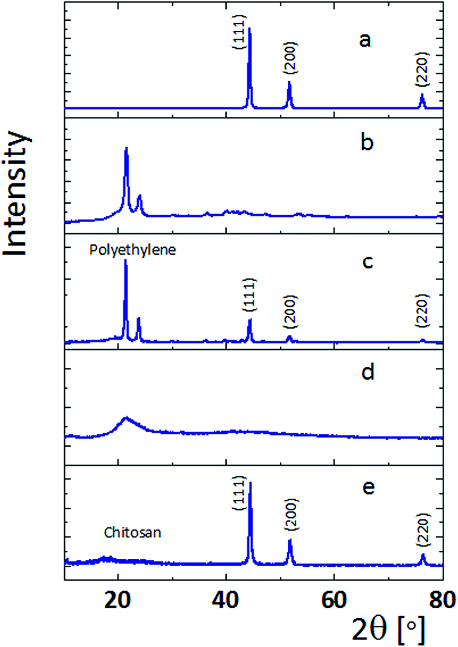 | ||
| Fig. 1 X-ray powder diffraction pattern of nickel nanocomposites (a) Ni0-NPs; (b) polyethylene (Pe) matrix; (c) Ni–Pe1 composite; (d) chitosan (Ch) matrix; (e) Ni–Ch1 composite. | ||
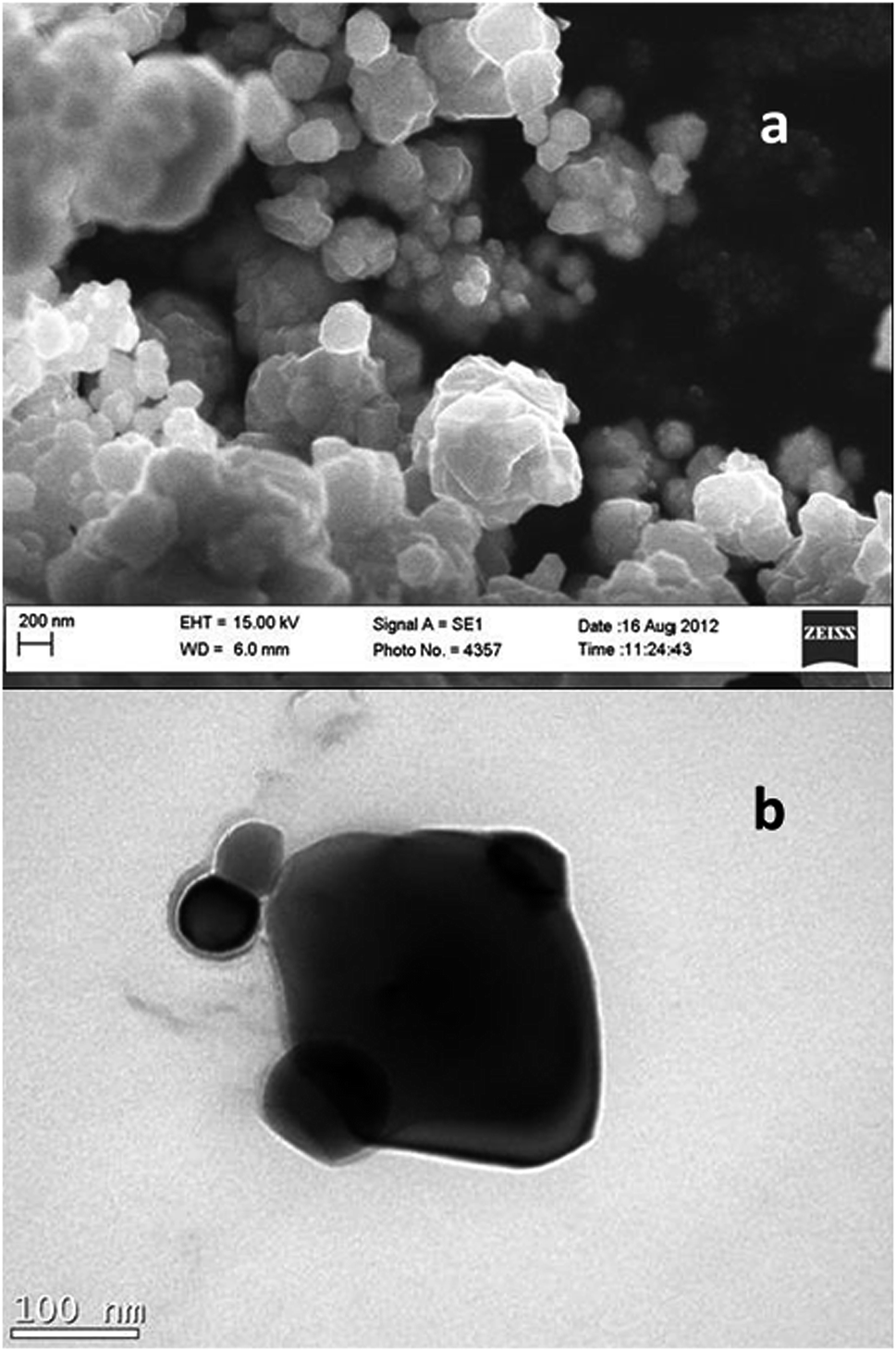 | ||
| Fig. 2 (a) SEM image of Ni0-NPs; (b) TEM image of Ni0-NPs. | ||
Fig. 3 shows the SEM images obtained for the nanocomposites Ni–Pe1, Ni–Pe3, Ni–Ch1 and Ni–Ch3. The SEM images for composites Ni–Pe2, Ni–Pe4, Ni–Ch2 and Ni–Ch4 are given as ESI.† The micrographs show that the use of the organic matrix changes the size and distribution of the metallic particles, showing in all cases a more homogenous dispersion as compared with the isolated Ni0-NPs. While the spherical shape observed for the Ni0-NPs is retained on the matrices, the size agglomerates are smaller than 100 nm and with less size variability, as compared with the Ni0-NPs synthesized without the presence of the organic matrices. The SEM micrographs show that in the case of nanocomposites obtained from most concentrated solutions of metallic salt, metallic nanoparticles forming agglomerates with larger sizes can be detected (Fig. 3 and 3S†). With a higher concentration of metallic nanoparticles (Ni–Pe1 and Ni–Ch1), the dispersion in both matrices appears very similar, and considering the morphological characteristics of each matrix, no significant changes in the size or shape of Ni0-NPs grafted onto the matrix surface are observed. However, as the concentration of the nickel nanoparticles decreases, some differences among the composites become evident. Thus, Ni–Pe3 and Ni–Ch3 with the same size and shape of the nanoparticles have a completely different dispersion. Furthermore, Ni–Ch3 retains the same dispersion distribution as Ni–Ch1, while Ni–Pe3 shows important changes as compared with Ni–Pe1. The presence of metallic domains (islands) can be observed for this polyethylene composite when an M:AA molar ratio of 0.25:1 is used. To the best of our knowledge, this island type dispersion for nickel nanoparticles has not been reported to date in the literature. Although Suzuki et al.32 and Byeon et al.33 have used the term metallic islands or nanoscaled islands for silver and gold nanoparticles deposited on a silicon substrate, the form of the nickel island deposited in the polyethylene matrix is completely different from those reported by these authors. Comparing the samples with the lower amount of metallic nanoparticles (Ni–Pe4 and Ni–Ch4 (M:AA = 0.125:1), it is possible to observe some differences among the composites. No metallic islands are observed, and Ni–Pe4 shows a more homogenous dispersion than Ni–Ch4. Moreover, Ni–P4 and Ni–Ch4 composites are characterized by not presenting large agglomerates of nickel nanoparticles. Another important aspect is the amount of Ni0-NPs on the organic matrices (Table 1). According to the data, the chitosan matrix doubles the concentration of metallic nickel, as compared with the polyethylene composite. This can be related to the fact that chitosan is rich in functional groups that can interact with the nickel ions and promote the reduction process, leading to the formation of the nanoparticles.
 | ||
| Fig. 3 SEM images of nickel nanocomposites. (a) Ni–Pe1; (b) Ni–Pe3; (c) Ni–Ch1; (d) Ni–Ch3. | ||
| Nanocomposite | Hc [Oe] | Ms [emu g−1] | Mr/Ms | Ni [%] |
|---|---|---|---|---|
| Ni–Pe1 | 126 | 9.2 | 0.14 | 16.7 |
| Ni–Pe2 | 122 | 2.1 | 0.13 | 3.8 |
| Ni–Pe3 | 145 | 0.5 | 0.18 | 0.9 |
| Ni–Pe4 | 146 | 0.1 | 0.14 | 0.2 |
| Ni–Ch1 | 137 | 13.1 | 0.20 | 23.8 |
| Ni–Ch2 | 140 | 4.8 | 0.18 | 8.7 |
| Ni–Ch3 | 170 | 0.7 | 0.19 | 1.3 |
| Ni–Ch4 | 226 | 0.1 | 0.14 | 0.2 |
Taking into account that the Mr values depend on particle elongation, interaction effects, thermal activation, cubic magnetocrystalline and uniaxial components or formation of domain structures,34 as well as considering the relatively large size of the particles (>60 nm) and the quasi spherical form evidenced from SEM images, it is possible to suggest that the lower remanence value observed for the synthesized nickel nanoparticles is produced mainly by interaction effects or domain structure formation. The last is also consistent with the particle aggregation observed through the SEM images, where it is possible to observe that the distance between particles is the same as the diameter.
Fig. 4 shows the magnetic hysteresis observed for the nickel composites. All composites are characterized to have a weak ferromagnetic behaviour with Hc values similar to the one obtained for Ni0-NPs6 and with similar hysteresis loops reaching saturation at approximately 3 kOe. The magnetic parameters are given in Table 1. In the case of polyethylene composites, Ni–Pe1 and Ni–Pe2, similar values of Hc (≈120 Oe) are observed. However, Ni–Pe3 and Ni–Pe4, which were prepared using a lower M:AA ratio present slightly higher coercivity values (ca. 140 Oe). The same behaviour is also observed for chitosan composites with Ni–Ch4 composite exhibiting the highest Hc value (226 Oe). The higher values of the coercivity observed at the lower ratio of M:AA can be associated to the different distribution of the magnetic particles on the matrices, and therefore to the interactions between them. C. Cruzat et al.35 also synthesized nickel nanoparticles with sizes between 10 and 80 nm using chemical liquid deposition and solvated metal atom dispersive techniques and deposited them on chitosan; however, unlike this work, the authors reported a superparamagnetic behaviour for the particles. Besides, Hui et al.36 reported nickel nanoparticles on a carbon matrix (Ni@C) with Ms values similar to those reported for Ni–Pe1 and Ni–Ch1 (9.2 and 13.1 emu g−1 respectively). The authors explain that the lower value obtained for Ms (11.82 emu g−1) with Ni@C, compared with that reported for bulk Ni0, is a consequence of the matrix contribution. Considering this fact, and disregarding any change of Ms on the surface, a saturation value of 55 emu g−1 was taken as reference to estimate the amount of magnetic material present in the as-synthesized nickel nanoparticles. The calculated value was ca. 84%, which is in the range obtained from TEM images, if 10% to 19% of organic coating is considered. The same procedure was used to calculate the amount of magnetic material in the composites (Table 1).
 | ||
| Fig. 4 M(H) plots of (a) Ni0-NPs, (b) Ni–Pe1, and (c) Ni–Ch1. | ||
 | ||
| Scheme 1 | ||
The catalytic study was performed taking into account the characteristics of the composites that act as a heterogeneous catalyst. All the experiments were performed using the same amount of composite (30 mg). Fig. 5 shows the conversion as a function of the reaction time for the used catalysts. In all the cases, the catalytic activity starts after 15 minutes of reaction time (induction time); then, the transformation of acetophenone to 1-phenylethanol gradually increases. For short reaction times, the used composites have higher conversion compared with the nickel nanoparticles, reaching values of ca. 55%, 50% and 40% for Ni–Ch2, Ni–Pe2 and Ni0–NPs, respectively, at 60 minutes. The obtained results show that the nickel nanoparticles forming part of a composite are better catalysts in the studied reaction, compared with the coated Ni0–NPs. At 90 minutes, the conversion reaches values of 65%, 48% and 55% for Ni–Ch2, Ni–Pe2 and Ni0-NPs, respectively. The selectivity for all the studied catalysts was 100%, as compared to the commercial catalyst Nickel RANEY®, which produces ethylbenzene instead of 1-phenylethanol under the same experimental conditions.37 Furthermore, other nickel catalysts such as Ni–Al, Ni/TiO2, Ni/SiO2–Al2O3 and NiO were studied by Alonso et al.,19 but these catalysts did not present catalytic conversion towards any product. However, in this study, the reaction was carried out without the presence of a base. The conversion value of 40% at 60 min of reaction time, observed for the as-synthesized Ni0-NPs with agglomerates in the range of 100 to 800 nm, is lower than that reported by Alonso et al. for spherical Ni0-NPs with a diameter of <2 nm.19 Thus, the importance of the size of the Ni-NPs becomes relevant, when comparing catalytic activities.
 | ||
| Fig. 5 Conversion percentage as function of reaction time for the heterogeneous hydrogen-transfer reaction using Ni0-NPs, Ni–Pe2 and Ni–Ch2 as catalysts. | ||
According to previous studies, when transition metals are involved, the catalytic hydrogen transfer proceeds through the hydridic route. However, Alonso et al. reported that, for Ni0-NPs, the dihydride-type mechanism is more in agreement with the data obtained with deuterated isopropanol.38 Thus, the induction time evidenced during the first 15 min can be related with the coating of the superficial metallic particles of the composite, which must be removed to permit the formation of the nickel dihydride. According to the proposed mechanism, this species would be necessary for the transformation of acetophenone to 1-phenylethanol.
As can be observed in Fig. 5, the Ni–Ch2 composite presents a higher conversion value at 60 min (65%), compared to Ni–Pe2 and Ni0-NPs. As discussed above, the morphological characteristics of both composites Ni–Ch2 and Ni–Pe2 should be responsible for the difference in the catalytic activities. It is interesting to observe that at 30 min, the polyethylene composite has the best catalytic activity, as compared with that of Ni–Ch2 and Ni0-NPs. Moreover, the same composite reaches the maximum conversion at 40 minutes, whereas the chitosan composite continues showing an increase in the conversion percentage at 90 minutes. Thus, it can be concluded that as the reaction time advances, the Ni–Ch2 composite becomes a better catalyst. It must be taken into account that the dispersion of the NPs and molecular structure of the matrix are different in both composites; therefore, the catalytic behaviour is expected to be dissimilar. Dutta et al.39 discussed the effect of the used amount of catalyst on the conversion values, and their conclusions are in accordance with those reported in this study. These authors synthesized Ni0-NPs, supported on montmorillonite, using the pores of the matrix to obtain spherical Ni0-NPs with sizes smaller than 8 nm. The authors report a very high catalytic activity (using similar reaction conditions to those of this work), obtaining a conversion of about 100% for 4 hours of reaction time. However, the conversion is only 17% after 1 hour of reaction time, which is much lower than that obtained in this study (ca. 50%) for both studied composites. In addition, yolk–shell-type Ni0-NPs (Ni@SiO2) have been studied for the same reaction at 150 °C by Park et al.40 These authors report a conversion of 90% for 1 hour of reaction. The same authors also report that the conversion value is lower when the temperature is 100 °C (68%) or 80 °C (61%); these values are in the range of those obtained in this study. Moreover, Park et al. also showed that the particle size affects the catalytic process; 90% of conversion was obtained at 150 °C with particles of 3 nm. This conversion decreased 10% when the particle size was increased to 30 nm.
Taking into account the reported data, the catalytic activity of the synthesized composites is in agreement with the fact that the larger size of the NPs decreases the performance of the used catalysts. However, the fact that the amount of Ni0-NPs on the studied matrices is ca. half for the Ni–Pe2 composite compared to that of Ni–Ch2 could explain the better performance of the latter at longer times of reaction if a deactivation process is considered to take place.
Conclusions
Using a solvothermal technique, it was possible to synthesize Ni0-NPs that were stable to air oxidation; besides, these NPs were also dispersed on chitosan and polyethylene matrices. The resulting composites present smaller-size metallic particles as compared with the isolated Ni0-NPs, making evident the role of the organic matrices on the dispersion of the magnetic particles. All the composites exhibited a weak ferromagnetic behaviour with coercivity values ranging from 120 to 220 Oe, and can classified as soft magnets. Ni0-NPs and the composites Ni–Pe2 and Ni–Ch2 were also employed as catalysts for the heterogeneous hydrogen-transfer reaction for acetophenone, reaching conversion values between 35% and 65%, depending on the reaction time. The highest conversion value was observed for Ni–Ch2 composite at 90 minutes, which may be due to the dispersion of the NPs and molecular structure of the matrix.Acknowledgements
The authors acknowledge CONICYT-FONDEQUIP/PPMS/EQM130086 grant and financial support from Proyecto Basal CEDENNA, Financiamiento Basal FB0807, and Laboratorio de Caracterização Magnética, LMCMM-UFSC, Departamento de Física and Centro de Microscopia Electrónica, CME-UFSC, Universidade Federal do Santa Catarina. C. C. thanks CONICYT for the Doctoral fellowship 21110032.References
- (a) M. R. Knecht, J. C. García-Martinez and R. M. Crooks, Chem. Mater., 2006, 18, 5039 CrossRef CAS; (b) N. C. Nelson, T. Purnima, A. Ruberu and M. D. Reichert, J. Phys. Chem. C, 2013, 117, 25826 CrossRef CAS.
- C. Rui-ying, Trans. Nonferrous Met. Soc. China, 2006, 16, 1223 CrossRef.
- Q. Zhen-Ping, G. Hong-Xia, L. Dong-Sheng and S. Xue-Ping, J. Funct. Mater. Devices, 2004, 10, 95 Search PubMed.
- H. Yuan-Qing, L. Xue-Geng and M. Swihart, Chem. Mater., 2005, 17, 1017 CrossRef.
- L. Zhao-Ping, L. Shu, Y. You, P. Sheng, H. Zhao-Kang and Q. Yi-Tai, Adv. Mater., 2003, 15, 1946 CrossRef PubMed.
- V. Paredes-Garcia, C. Cruz, J. Denardín, D. Venegas-Yazigi, C. Castillo, E. Spodine and Z. Luo, New J. Chem., 2014, 38, 837 RSC.
- Y. Lan, W. Luo and X. Wang, West Leacher, 2002, 2, 20 Search PubMed.
- G. Bao-Jiao, G. Jian-Feng and Z. Jia-Qi, Chin. J. Inorg. Chem., 2001, 17, 491 Search PubMed.
- D. Chen and S. Wu, Chem. Mater., 2000, 12, 1354 CrossRef CAS.
- D. Shi, P. He, P. Zhao, F. Guo, F. Wang, C. Huth, X. Chaud, S. Bud'ko and J. Lian, Composites, Part B, 2011, 1532 CrossRef CAS PubMed.
- K. Nielsch, R. B. Wehrspohn, J. Barther, J. Kirschner, S. F. Fischer, H. Kronmuller, T. Schweinbock, D. Weiss and U. Gosele, J. Magn. Magn. Mater., 2002, 249, 234 CrossRef CAS.
- J. C. Bao, C. Y. Tie, Z. Xu, Q. F. Zhou, D. Shen and Q. Ma, Adv. Mater., 2001, 13, 1631 CrossRef CAS.
- L. Dayong, R. Shan, W. Hui, Z. Qingtang and W. Lishi, J. Mater. Sci., 2008, 43, 1974 CrossRef.
- R. Akbarzadeh and H. Dehghani, Dalton Trans., 2014, 5474 RSC.
- J. Zhang, K. Yanagisawa, S. Yao and H. Wong, J. Mater. Chem. A, 2015, 3, 7877 CAS.
- Y. Qiua, H. Zhenga, J. Geng, B. Johnson, B. Zhou, S. Hermans and G. Somorjai, Nanocompos. Sci. Technol., 2004, 1, 159 Search PubMed.
- F. Alonso and M. Yus, Chem. Soc. Rev., 2004, 33, 284 RSC.
- J. Geng and B. Johnson, Nanocompos. Sci. Technol., 2004, 1, 159 CAS.
- F. Alonso, P. Riente and M. Yus, Tetrahedron, 2008, 64, 1847 CrossRef CAS PubMed.
- F. Alonso, P. Riente and M. Yus, Tetrahedron Lett., 2008, 49, 1939 CrossRef CAS PubMed.
- R. Larock, Comprenhensive Organic Transformation: a Guide to Funtional Group Preparations, Wiley-VCH, New York, 2nd edn, 1999 Search PubMed.
- M. Harrad, B. Boualy, L. Firdoussi, A. Mehdi, C. Santi, S. Giovagnoli, M. Nocchetti and M. Ait, Catal. Commun., 2013, 32, 92 CrossRef CAS PubMed.
- T. Subramanian and K. Pitchumani, Catal. Commun., 2012, 29, 109 CrossRef CAS PubMed.
- V. Rodriguez-Gonzales, S. Alfaro, A. Zaldivar-Cadena and S. Lee, Catal. Today, 2011, 166, 166 CrossRef PubMed.
- J. Sun and X. Bao, Chem.–Eur. J., 2008, 14, 7478 CrossRef CAS PubMed.
- R. White, R. Luque, V. Budarin, J. Clark and D. Macquarrie, Chem. Soc., 2009, 38, 481 CAS.
- J. Campelo, D. Luna, R. Luque, J. Marinas and A. Romero, ChemSusChem, 2009, 2, 18 CrossRef CAS PubMed.
- J. De'Rogatis, M. Cargnello, V. Gombac, B. Lorenzut, T. Montini and P. Fornasiero, ChemSusChem, 2010, 3, 24 CrossRef PubMed.
- H. Sakurai and A. Murugadoss, J. Mol. Catal. A: Chem., 2011, 341, 1 CrossRef PubMed.
- M. Khairy, S. El-Safty, M. Ismael and H. Kawarada, Appl. Catal., B, 2012, 127, 1 CrossRef CAS PubMed.
- F. Jia, L. Zhang, X. Shang and Y. Yang, Adv. Mater., 2008, 20, 1050 CrossRef CAS PubMed.
- Y. Suzuki, Y. Sumi, K. Kita, T. Miyanaga and K. Sagisaka, Surf. Interface Anal., 2006, 38, 1296 CrossRef CAS PubMed.
- J. Byeon and J. Roberts, Langmuir, 2014, 30, 8770 CrossRef CAS PubMed.
- J. Geshev, A. Viegas and J. Echmidt, J. Appl. Phys., 1998, 84, 1488 CrossRef CAS PubMed.
- C. Cruzat, O. Peña, M. Meléndrez, J. Díaz-Visurraga and G. Cárdenas, Colloid Polym. Sci., 2011, 289, 21 Search PubMed.
- Z. Hui, R. Zhang, X. Ying, X. Liang and T. Zhoub, Appl. Surf. Sci., 2012, 263, 795 CrossRef PubMed.
- M. Andrews and C. Pillai, Indian J. Chem., Sect. B: Org. Chem. Incl. Med. Chem., 1978, 16, 465 Search PubMed.
- (a) J. E. Bäckvall, J. Organomet. Chem., 2002, 652, 105 CrossRef; (b) J. Trocha and H. B. Henbest, Chem. Commun., 1967, 545 Search PubMed.
- D. Dutta, B. Borah, L. Saikia and M. Pathak, Appl. Clay Sci., 2011, 53, 650 CrossRef CAS PubMed.
- X. J. Park, H. Lee, J. Kim, K. Park and H. Song, J. Phys. Chem. C, 2010, 114, 6381 Search PubMed.
Footnote |
| † Electronic supplementary information (ESI) available: Fig. 1S X-ray powder diffraction pattern of nickel nanocomposites. Fig. 2S EDX spectra of (a) Ni–Pe1; (b) Ni–Ch1. Fig. 3S SEM images of nickel nanocomposites (a) Ni–P2; (b) Ni–P4; (c) Ni–C2; (d) Ni–C4. See DOI: 10.1039/c5ra09622g |
| This journal is © The Royal Society of Chemistry 2015 |