
Silver nanoparticle decorated polyaniline–zeolite nanocomposite material based non-enzymatic electrochemical sensor for nanomolar detection of lindane†
Balwinder Kaura,
Rajendra Srivastava*a and
Biswarup Satpati b
b
aDepartment of Chemistry, Indian Institute of Technology Ropar, Rupnagar-140001, India. E-mail: rajendra@iitrpr.ac.in; Fax: +91-1881-223395; Tel: +91-1881-242175
bSurface Physics and Material Science Division, Saha Institute of Nuclear Physics, 1/AF, Bidhannagar, Kolkata 700 064, India
First published on 16th June 2015
Abstract
In this study, a silver nanoparticle decorated polyaniline-nanocrystalline zeolite organic–inorganic hybrid material was synthesized. The material was characterized by the complementary combination of X-ray diffraction, N2-adsorption, scanning/transmission electron microscopy, and thermogravimetric analysis. An electrochemical sensor based on the silver nanoparticle decorated polyaniline-nanocrystalline zeolite was developed for the nanomolar detection of lindane in an aqueous solution of methanol with high electro-catalytic activity, stability, sensitivity, and selectivity. The sensor exhibited a wide linear range from 10 nM to 900 μM with a limit of detection of 5 nM under the optimum conditions. The analytical performance of the developed sensor was demonstrated for the determination of lindane in different water bodies with satisfactory recovery.
Introduction
Environmental legislations restrict the use of polychlorinated organic compounds and solvents.1 It is interesting to note that many of these compounds (such as lindane) exhibit very useful insecticidal properties.2 Lindane was registered as an agricultural insecticide in the 1940s and as a pharmaceutical in 1951.3,4 The use of lindane for smoke fumigation is no longer permitted, and its use as an insecticide has been banned in many countries. However, the use of lindane in lotions to combat lice is still permitted in many countries.3,5 Research has led us to conclude that the long-term exposure of organochlorine pesticides may result in various nonspecific symptoms, including headache, nausea, fatigue, muscle twitching, and visual disturbances.5 In addition, the chronic exposure of these agents may be associated with the development of blood dyscrasias, including anemia and leukemia in humans.6 Lindane has been shown to accumulate in the food chain because animals, including humans, eat food grown in lindane-contaminated soil.7 High levels of lindane exposure may cause acute poisoning in fishes and mammals, which is manifested as nervous system dysfunction.5 Chronic exposure may adversely affect liver function in humans. Lindane is not bio-degradable and accumulates in human blood, breast milk, and adipose tissues.8 Therefore, a simple, rapid, and sensitive method for lindane detection is highly desirable. In recent years, electrochemical methods have attracted an increasing interest in the rapid and accurate detection of environmental pollutants and physiologically important bio-molecules.9–12The electrochemical detection of polychlorinated organic compounds depends on the electrochemical activation of carbon–chlorine bond, which requires a large negative potential.13 To overcome this problem, transition metal based homogeneous complexes have been investigated as catalysts for the reductive cleavage of the carbon–halogen bond.14–16 The electroreduction of these compounds at Pd, Cu, and Ag surfaces has been investigated.13,17 In general, the molecular structure of the organic halide, the surface morphology of the electrode, the adsorption/diffusion of organic halide and its reduced products influence the electro-catalytic process. The catalytic surface modifies the reaction scheme through the formation of a more favourable activated complex and adsorption of halide anions.18,19 After understanding the various factors that influence the electroreduction process, one can easily conclude that nanocomposite materials could play a very important role in the detection of lindane. One of the aims of our research group is to develop nanocomposite materials based on zeolite, polyaniline (PANI), and metal oxides for the electrochemical detection of important biomolecules and organic pollutants found in water bodies.20–22 We have demonstrated the use of nanocrystalline zeolites in the detection of biomolecules and organic water pollutants.21,22 Because the electroreduction process requires a large negative potential, it is important to develop materials that exhibit high conductivity and electroactivity. We have shown the high electroactivity of polyaniline–zeolite nanocomposite material compared to polyaniline or nanocrystalline zeolite.23 A literature report suggests that Ag plays an important role in the electroreduction of lindane.17 Therefore, in this study, Ag nanoparticles supported on a polyaniline–zeolite nanocomposite material was developed for the detection of lindane.
In this study, we present the synthesis of a silver nanoparticle decorated nanoporous polyaniline–zeolite (AgNPs-PANI-Nano-ZSM-5) nanocomposite material. The potential application of the synthesized nanocomposite material is demonstrated in the electrochemical detection of lindane. The AgNPs-PANI-Nano-ZSM-5 based electrochemical sensor exhibited excellent sensitivity, a wide linear range, and a lower limit of detection towards lindane. To the best of our knowledge, this is the first report that deals with the electrochemical sensing of lindane using the AgNPs-PANI-Nano-ZSM-5 nanocomposite as an electrode material.
Experimental
Synthesis of AgNPs decorated PANI-Nano-ZSM-5 nanocomposites
Nanocrystalline ZSM-5 zeolite (Nano-ZSM-5) was prepared using molar composition TEOS/10![[thin space (1/6-em)]](https://www.rsc.org/images/entities/char_2009.gif) :PrTES/2.5:Al2O3/3.3:Na2O/25:TPAOH/2500:H2O by following a reported procedure.20 Propylamine was then covalently anchored onto the external surface of Nano-ZSM-5. Nano-ZSM-5 (2 g) and (3-aminopropyl)trimethoxysilane (1.43 g) were placed in 50 mL toluene and the reaction mixture was refluxed for 12 h. After the reaction, the reaction mixture was filtered and the solid sample was washed with toluene, followed by acetone, and dried at 323 K for 24 h in an oven to obtain propyl amine-functionalized Nano-ZSM-5 (hereafter represented as Nano-ZSM-5-Pr-NH2).
:PrTES/2.5:Al2O3/3.3:Na2O/25:TPAOH/2500:H2O by following a reported procedure.20 Propylamine was then covalently anchored onto the external surface of Nano-ZSM-5. Nano-ZSM-5 (2 g) and (3-aminopropyl)trimethoxysilane (1.43 g) were placed in 50 mL toluene and the reaction mixture was refluxed for 12 h. After the reaction, the reaction mixture was filtered and the solid sample was washed with toluene, followed by acetone, and dried at 323 K for 24 h in an oven to obtain propyl amine-functionalized Nano-ZSM-5 (hereafter represented as Nano-ZSM-5-Pr-NH2).
In a typical synthesis of PANI-Nano-ZSM-5 nanocomposite, first P123 (0.150 g) was dispersed in 500 mL of deionized water. Then, 0.5 g of Nano-ZSM-5-Pr-NH2 was added to this mixture followed by the addition of sodium dodecyl sulfate (0.312 g). The mixture was ultrasonically dispersed for 15 min. A solution of aniline (0.5 g) and HCl (10 mL, 1 M) was added dropwise to the above mentioned mixture with vigorous stirring. The mixture was kept in a cold water bath (∼290 K) and mechanically stirred for 30 minutes. Then, an ice-cold aqueous solution of APS (2.45 g of APS in 10 mL of deionized water) was added into the above mentioned mixture instantly to start the oxidative polymerization and the reaction was allowed to proceed for 5 h with mechanical stirring. After the reaction, the resulting precipitate was washed with 0.1 M ammonium acetate followed by deionized water and ethanol several times. The final product was dried in a vacuum oven at 333 K for 12 h to obtain the PANI-Nano-ZSM-5 nanocomposite. For comparison, conventional PANI was prepared using a reported procedure.24
For the synthesis of silver nanoparticle decorated PANI-Nano-ZSM-5 nanocomposite (hereafter represented as AgNPs(5%)-PANI-Nano-ZSM-5), first AgNO3 (15.8 mg) was dissolved in 15 mL of deionized water. AgNO3 solution was added dropwise to a 50 mL aqueous solution containing sodium dodecyl sulfate (62.3 mg) and NaBH4 (35.7 mg) at 276–277 K under magnetic stirring. The reaction was continued for 30 min at 276–277 K with constant stirring. This resulted in the formation of a dark grey colloidal dispersion due to the formation of Ag nanoparticles. In another beaker PANI-Nano-ZSM-5 (200 mg) was dispersed in 10 mL deionized water. This dispersed PANI-Nano-ZSM-5 was then added to the colloidal dispersion of Ag nanoparticles at ambient temperature and kept under stirring for 5 h. The resulting product was centrifuged, and washed with ethanol and water followed by drying in a vacuum oven at 333 K. AgNPs-PANI-Nano-ZSM-5 nanocomposites with different weight ratios (2, 6, and 10, denoted for AgNPs(2%)-PANI-Nano-ZSM-5, AgNPs(6%)-PANI-Nano-ZSM-5, and AgNPs(10%)-PANI-Nano-ZSM-5, respectively) were also synthesized using the similar procedure by varying the amount of AgNO3. For comparison, silver nanoparticles supported conventional PANI (AgNPs(5%)-PANI) and silver nanoparticles supported Nano-ZSM-5 (AgNPs(5%)-Nano-ZSM-5) were also prepared using the above mentioned procedure.
Electrode fabrication
Cyclic voltammetry (CV) and differential pulse voltammetry (DPV) studies were performed using a Potentiostat-Galvanostat, BASi EPSILON, USA. A three-electrode electrochemical cell was employed with Ag/AgCl as the reference electrode (3 M KCl), AgNPs-PANI-Nano-ZSM-5 mounted on glassy carbon (3 mm diameter) as the working electrode and Pt foil as the counter electrode. Before modification, the glassy carbon electrode (GCE) was first polished to a mirror-like surface with an alumina slurry and then ultrasonicated in ethanol and deionized water for 5 min. A 10 μL aliquot of AgNPs-PANI-Nano-ZSM-5 suspension (a homogenous sonicated solution of 2 mg AgNPs-PANI-Nano-ZSM-5 nanocomposite, 10 μL Nafion and 1 mL deionized water) was placed onto the GCE surface. The electrode was dried in air, leaving the material mounted onto the GC surface. For comparison, other modified glassy carbon electrodes were also fabricated in a similar way. Electrochemical impedance spectroscopy (EIS) was performed using an Autolab PGSTAT302N. The fabrication of the electrochemical sensor is presented in Scheme 1. | ||
| Scheme 1 Mechanistic representation for the fabrication of AgNPs(5%)-PANI-Nano-ZSM-5/GCE electrochemical sensor. | ||
Results and discussion
Physico-chemical characterization
Nano-ZSM-5 exhibited an XRD pattern corresponding to a highly crystalline MFI framework structure with high phase purity (Fig. 1a). MFI is a three letter code suggested by the International Zeolite Association for the ZSM-5 framework topology. The XRD pattern of Nano-ZSM-5 is broad, confirming the nanocrystalline nature of the material. No change in the XRD pattern of Nano-ZSM-5-Pr-NH2 was observed after the functionalization (figure not shown), which confirms that the framework structure was not affected after the functionalization. Two broad diffraction peaks at 2θ = 20.5° and 25.1° were obtained in the XRD pattern of PANI, which represent the periodicities parallel (100) and perpendicular (110) to the PANI chain, respectively (Fig. 1a). The XRD pattern of PANI-Nano-ZSM-5 exhibited the diffraction peaks corresponding to both, PANI and Nano-ZSM-5 phases (Fig. 1a). AgNPs(5%)-PANI-Nano-ZSM-5 also show diffraction peaks corresponding to PANI and Nano-ZSM-5 phases. Furthermore, the XRD pattern of AgNPs(5%)-PANI-Nano-ZSM-5 exhibited four additional diffraction peaks located at 2θ = 38.1°, 44.4°, 64.5°, and 77.4°, which are assigned to the (111), (200), (220), and (311) Bragg's reflections of the cubic phase of metallic Ag [JCPDS Card Number-03-0931]. This confirms the formation of AgNPs on the PANI-Nano-ZSM-5 nanocomposite.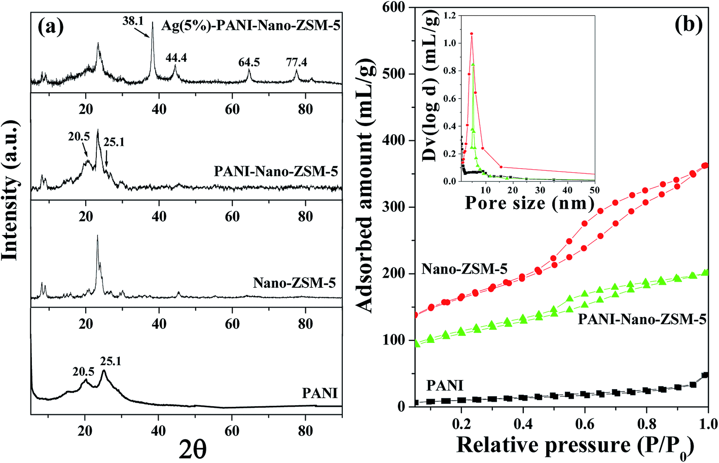 | ||
| Fig. 1 (a) XRD patterns of PANI, Nano-ZSM-5, PANI-Nano-ZSM-5, and AgNPs(5%)-PANI-Nano-ZSM-5; and (b) N2-adsorption isotherms of PANI, Nano-ZSM-5, and PANI-Nano-ZSM-5 materials. Inset shows the pore size distribution. | ||
The textural properties of the synthesized materials were investigated using nitrogen adsorption–desorption measurements. The N2-adsoption isotherms for Nano-ZSM-5 and PANI-Nano-ZSM-5 exhibited a type IV isotherm similar to that of mesoporous materials (Fig. 1b). A sharp increase in the volume of N2 adsorption in the region of 0.4 < P/Po < 0.9 is characteristic of the capillary condensation within the intercrystalline mesopore void spaces. The mesopores for Nano-ZSM-5 exhibited a pore size distribution in the range of 2–10 nm, whereas PANI-Nano-ZSM-5 showed a considerable narrow pore size distribution (4–8 nm). Textural properties of various materials investigated in this study are summarized in Table 1. The BET surface area and pore volume for PANI-Nano-ZSM-5 were found to be less when compared to Nano-ZSM-5. The decrease in the surface area indicates that PANI forms a thin coating around Nano-ZSM-5 particles. The total surface area and pore volume for conventional PANI were found to be very low when compared to Nano-ZSM-5 or PANI-Nano-ZSM-5.
| S.No. | Sample | Total surface area SBET (m2 g−1) | External surface area (m2 g−1) | Total pore volume (cm3 g−1) |
|---|---|---|---|---|
| 1 | Nano-ZSM-5 | 548 | 365 | 0.58 |
| 2 | PANI | 45 | — | 0.03 |
| 3 | PANI-Nano-ZSM-5 | 297 | 123 | 0.41 |
SEM was used to investigate the morphology of the materials studied. The SEM image shows an irregular aggregated morphology for the conventional PANI (Fig. S1a, ESI†). Uniform spherical particles were obtained for Nano-ZSM-5 (Fig. S1b, ESI†). The SEM image of PANI-Nano-ZSM-5 was found to be similar to that of Nano-ZSM-5, which confirms that a PANI film is formed on the surface of spherical Nano-ZSM-5 particles (Fig. S1c, ESI†). SEM images also confirmed that no separate phase for bulk PANI was observed. This provides indirect evidence that the growth of PANI occurred mainly at the Nano-ZSM-5 surface, and the bulk PANI phase was not formed in the material.
To obtain the in-depth information for AgNPs(5%)-PANI-Nano-ZSM-5, a TEM investigation was carried out (Fig. 2). Fig. 2a and b shows low-magnification TEM images, which clearly show that silver nanoparticles are dispersed on the surface of PANI-Nano-ZSM-5. The selected area electron diffraction (SAED) pattern is shown in Fig. 2c. The concentric ring consisting of distinct spots seen from this SAED pattern is a result of many small single crystals and suggests the crystalline nature of Ag nanoparticles. The SAED pattern was indexed to fcc-Ag and matches very well with the XRD results. The sizes of the silver nanoparticles vary between 5 and 20 nm as seen in the high magnification TEM image (Fig. 2d). The HRTEM image in Fig. 2e shows one crystalline Ag nanoparticle showing lattice fringes, and the measured lattice spacing was 2.32 Å, which corresponds to the (111) interplanar spacing (d-spacing) of Ag (d111 for Ag is 2.35 Å). To investigate the chemical composition of the nanoparticles and surrounding matrix, high angle annular dark field (HAADF) analysis was performed (Fig. 3). The chemical composition of the AgNPs(5%)-PANI-Nano-ZSM-5 was determined by EDX analysis (Fig. 3b). This confirmed the presence of Si, Al, C, O, and Ag elements in the material from the rectangular area 1 marked in Fig. 3a. For a detailed distribution of atomic contents in the material, elemental mapping was performed using the STEM-HAADF-EDX technique (Fig. 3c). Based on the TEM imaging and elemental mapping results, it can be concluded that Ag nanoparticles decorated PANI-Nano-ZSM-5 material was successfully prepared.
 | ||
| Fig. 2 (a and b) Low magnification TEM images. (c) The selected area electron diffraction (SAED) pattern showing the formation of silver nanoparticles. (d) High magnification TEM image showing silver nanoparticles decorated on the PANI-Nano-ZSM-5 surface. (e) HRTEM image showing one crystalline Ag nanoparticle for the AgNPs(5%)-PANI-Nano-ZSM-5 nanocomposite. | ||
 | ||
| Fig. 3 (a) STEM-HAADF image of AgNPs(5%)-PANI-Nano-ZSM-5 nanocomposite, (b) EDX spectra from a rectangular region marked by area 1 in (a) and (c) STEM-HAADF-EDX images obtained from the area marked by rectangular box 2, indicating the locations of different atoms across the structure. | ||
TGA curves for PANI-Nano-ZSM-5, Nano-ZSM-5-Pr-NH2, Nano-ZSM-5, and conventional PANI are shown (Fig. S2, ESI†). The first weight loss below 473 K in the TGA curves for all the samples indicates the loss of physically adsorbed water molecules. The TGA curve for Nano-ZSM-5 showed no appreciable weight loss after 473 K, confirming that chemical composition did not change in this temperature range. In the TGA curve for conventional PANI, the second sharp weight loss between 533 and 603 K may be attributed to the evaporation or decomposition of few unstable oligoanilines/dopants and the third weight loss after 603 K is attributed to the decomposition of PANI polymer chains. The total weight loss of PANI was 100% and the combustion of PANI in an air stream was completed at 913 K. In the TGA curve for Nano-ZSM-5-Pr-NH2, the second weight loss in the temperature range of 525–875 K can be attributed to the decomposition of organic propylamine moiety anchored onto the surface of Nano-ZSM-5. TGA analysis confirmed that Nano-ZSM-5-Pr-NH2 contains 11 wt% functionalized organic groups (–Pr–NH2). In the TGA curve for PANI-Nano-ZSM-5, the combustion of PANI in air stream was completed at 913 K and the residual weight refers to the content of Nano-ZSM-5 in the nanocomposite. TGA confirms that PANI-Nano-ZSM-5 nanocomposite contains 40.7 wt% Nano-ZSM-5 and 43.8 wt% PANI. Nano-ZSM-5/PANI weight ratio was found to be 0.93, which was very close to the initial weight ratio.
PANI-Nano-ZSM-5 hybrid material was synthesized by the oxidative polymerization of aniline with ammonium peroxydisulfate (APS) in an aqueous zeolite suspension by the in situ surface polymerization method. Nano-ZSM-5 was first surface functionalized with propylamine groups to overcome the hydrophilic character of Nano-ZSM-5, which favored the growth of PANI film on the surface of Nano-ZSM-5 and not in the bulk solution. P123 is a neutral polymeric surfactant and is used to prepare a variety of mesostructured materials.24,25 P123 is amphiphilic and non-ionic surfactant and it can form polymer coils in aqueous solutions under dilute concentrations.26 P123 macromolecules could be attached to the peripheral amine groups of Nano-ZSM-5 nanoparticles through hydrogen bonding. Sodium dodecyl sulfate (SDS) was subsequently added to the solution, which could form a double surfactant layer with the negative polar head group of the SDS molecule. Aniline monomers could form cationic anilinium ions (An+) under acidic conditions. An+ could adsorb on the surface of Nano-ZSM-5 with electrostatic interaction with a double surfactant layer. Upon the addition of APS, PANI nucleation could take place, which could be stabilized by the P123/SDS double surfactant layer attached onto the Nano-ZSM-5 surface.27 The polymerization usually takes place preferentially and continuously in proximity of existing PANI. Hence, the polymerization was initiated, propagated, and terminated on the surface of Nano-ZSM-5, rather than in bulk solution. Therefore, the PANI film was formed on the surface of Nano-ZSM-5 (Scheme 1).
Electrochemical characteristics of modified electrodes
The electrochemical behavior of different modified electrodes (AgNPs(5%)-PANI-Nano-ZSM-5/GCE, PANI-Nano-ZSM-5/GCE, PANI/GCE, Nano-ZSM-5/GCE) and bare GCE was investigated using potassium ferricyanide as an electrochemical probe by CV. The study was performed in 0.1 M KCl solution containing 1 mM K3[Fe(CN)6]/K4[Fe(CN)6] at a scan rate of 10 mV s−1 with different modified working electrodes. The CV of various modified electrodes exhibited a pair of well-defined redox peaks corresponding to the Fe(CN)63−/4− redox couple (Fig. S3, ESI†). The CV result shows that the modified electrodes exhibited a higher peak current and lower peak potential when compared to the bare GCE. Furthermore, anodic to cathodic peak potential separation (ΔE) at these modified electrodes was decreased when compared to bare GCE (ΔE = 534 mV). CV results also show that the combination of PANI and Nano-ZSM-5 significantly improved the electro-catalytic activity compared to the individual constituents. CV results further show that the incorporation of AgNPs on PANI-Nano-ZSM-5 nanocomposite further facilitates the electron transfer rate due to the catalytic activity of the AgNPs. Among the various modified electrodes investigated in this study, AgNPs(5%)-PANI-Nano-ZSM-5/GCE exhibited the highest current response with the lowest ΔE (= 145 mV). The electroactive surface area of various electrodes was calculated according to the Randles–Sevcik equation. The effective surface area of different modified electrodes was calculated to be 1.32, 0.86, 0.34, and 0.32 cm2 for AgNPs(5%)-PANI-Nano-ZSM-5/GCE, PANI-Nano-ZSM-5/GCE, PANI/GCE, and Nano-ZSM-5/GCE, respectively. The high electroactive surface area of AgNPs(5%)-PANI-Nano-ZSM-5/GCE significantly facilitates the electron transfer rate at the electrode–electrolyte interface, which in turn is responsible for its higher electrochemical activity. EIS was used to further characterize the interface properties of the modified electrodes. EIS was carried out in 0.1 M KCl solution containing 10 mM K3[Fe(CN)6]/K4[Fe(CN)6] over a frequency range of 0.1 Hz to 105 Hz with the AC signal amplitude of 5 mV (Fig. 4). In a typical Nyquist plot, the semicircle portion corresponds to the electron-transfer resistance (Ret) at a higher frequency range, whereas a linear part at the lower frequency range represents the diffusion limited process. Fig. 4 shows that the bare GCE exhibited a large semicircle portion, indicating a high electron transfer resistance. Nano-ZSM-5/GCE exhibited a reduced semicircular domain and a linear portion, indicating the mixed charge transfer and diffusion kinetics controlled reaction. The modification of GCE with AgNPs(5%)-PANI-Nano-ZSM-5, PANI-Nano-ZSM-5 and PANI displayed an almost straight line, indicating the least electron transfer resistance at these modified electrodes. These observations indicate the promotion of electron transfer process at these modified electrode surfaces and enhancement in the diffusion of ferricyanide toward the electrode interface. | ||
| Fig. 4 Nyquist plots of impedance spectra at various modified electrodes and bare GCE in 0.1 M KCl solution containing 10 mM [Fe(CN)6]3−/4− over a frequency range from 0.1 Hz to 105 Hz. | ||
Electrochemical reduction of lindane
AgNPs(5%)-PANI-Nano-ZSM-5/GCE was applied for the electrochemical reduction of lindane because of its higher electrochemical activity. Fig. 5 shows the CV at AgNPs(5%)-PANI-Nano-ZSM-5/GCE before and after the addition of lindane (100 μM) at a scan rate of 50 mV s−1. The CV results show that no peak was obtained in the absence of lindane. When lindane was added, an irreversible, distinct, and well-defined reduction peak at −147 mV was obtained, indicating a rapid reduction of lindane at AgNPs(5%)-PANI-Nano-ZSM-5/GCE. CV was further used to investigate the effect of scan rate on the reduction peak current of lindane (Fig. S4, ESI†). CV was recorded at different scan rates at AgNPs(5%)-PANI-Nano-ZSM-5/GCE in the presence of 50 μM lindane (Fig. S4, ESI†). CV results show that only a reduction peak (no reverse peak was obtained) was obtained at different scan rates, which confirmed that the reduction of lindane is an irreversible electrode process. Furthermore, with increasing scan rate, the reduction peak potential shifted to negative potentials. The plot of reduction peak current against the square root of scan rate shows a linear relationship (inset of Fig. S4, ESI†). This shows that lindane undergoes a diffusion controlled reduction process.28 | ||
| Fig. 5 Comparison of CVs in 0.05 M TBAB solution in 60:40 (v/v) methanol–water (10 mL) in the absence (0 μM) and presence of lindane (100 μM) at AgNPs(5%)-PANI-Nano-ZSM-5/GCE at a scan rate of 50 mV s−1. The arrow indicates the starting point. | ||
The mechanism of lindane reduction can be studied with the help of voltammetric response. The reduction of lindane proceeds via a dissociative electron transfer (DET) mechanism.13,29 Electron transfer and bond rupture may occur either in a step-wise manner with the formation of an intermediate radical anion or in a concerted manner, yielding a radical and an ion.13 Furthermore, the electro-catalytic reduction of lindane also depends on the medium of investigation.17,28 Literature reports suggest that the methanol–water medium is favourable for the reduction of lindane to benzene.29–32 It is reported that water acts as a proton donor for electrogenerated carbanion intermediates, which undergoes a six-electron reduction to give benzene almost exclusively.17 Therefore, in this study, the methanol–water medium was chosen for further study. The results obtained from the voltammetric analyses are summarized in Table S1, ESI.† The electron transfer coefficient (α) is indicative of whether the process proceeds via step-wise or concerted pathways.13,19,29 In the case of the concerted mechanism, the heterogeneous electron transfer is very slow because a bond is to be broken along with the electron transfer. For a concerted pathway, the value of α was found to be approximately 0.3, whereas for a step-wise pathway, it should be more than 0.7.13 Based on the results obtained in this study, one can say that the reduction of lindane at AgNPs(5%)-PANI-Nano-ZSM-5/GCE is a concerted dissociative electron transfer process and matches well with the literature reports.13,29 The number of electrons transferred in the reduction of lindane was calculated to be 6 (details are provided in the ESI† section). This shows that initial electron transfer is followed by reduction; thus, lindane undergoes an overall six electron reduction. This suggests the formation of benzene as the final reduction product, which is in accordance with the literature reports.13,28,29,32 Hence, the cleavage of carbon–chlorine bonds in lindane could take place very fast and readily to form fully reduced benzene at AgNPs(5%)-PANI-Nano-ZSM-5/GCE. The mechanistic representation for the electrochemical reduction of lindane at AgNPs(5%)-PANI-Nano-ZSM-5/GCE is shown in Scheme S1, ESI.†
Fig. 6 shows the DPV response at AgNPs(5%)-PANI-Nano-ZSM-5/GCE with varying concentrations of lindane. The current obtained was proportional to the concentration of lindane in the reaction vessel. A linear response was obtained between the peak current and lindane concentration with a linear regression equation, I (μA) = −8.651 − 0.087C (μM) (R2 = 0.998) in the concentration range of 10 nM–900 μM with the sensitivity of 1.24 μA μM−1 cm−2 and a limit of detection (S/N = 3) of 5 nM. A comparison for the electrochemical reduction of lindane at a silver nanoparticle supported PANI-Nano-ZSM-5 nanocomposite modified GCE with different weight ratios is provided in Fig. S5, ESI.† With an increase in the amount of AgNPs on the PANI-Nano-ZSM-5 support, the electrochemical activity was increased. This shows that the higher loading of AgNPs in the nanocomposite material is better for the high electro-catalytic activity. However, with further increase in AgNPs content (after AgNPs(5%)), the electro-catalytic activity was not increased. The electro-catalytic activity of AgNPs(10%)-PANI-Nano-ZSM-5/GCE was found to be low when compared to AgNPs(5%)-PANI-Nano-ZSM-5/GCE. These results clearly show that the highly dispersed AgNPs on the surface of PANI-Nano-ZSM-5 enhance the accessibility of analytes to the active sites and improve the catalytic activity of nanocomposite material. Therefore, AgNPs(5%)-PANI-Nano-ZSM-5/GCE was chosen for lindane reduction.
 | ||
| Fig. 6 DPVs at AgNPs(5%)-PANI-Nano-ZSM-5/GCE using 0.05 M TBAB solution in 60:40 (v/v) methanol–water (10 mL) with varying concentrations of lindane. DPV parameters were selected as pulse amplitude: 50 mV, pulse width: 50 ms, scan rate: 20 mV s−1. Inset shows the calibration plot. The arrow indicates the starting point. | ||
DPV was further used to investigate the electro-catalytic activity of AgNPs(5%)-PANI/GCE and AgNPs(5%)-Nano-ZSM-5/GCE for lindane reduction. The reduction peak current was found to be linearly dependent on the concentration of lindane in the range of 8–200 μM with a sensitivity of 0.32 μA μM−1 cm−2 and a limit of detection (S/N = 3) of 2 μM at AgNPs(5%)-PANI/GCE. AgNPs(5%)-Nano-ZSM-5/GCE exhibited a linear range of 10–500 μM with a sensitivity of 0.26 μA μM−1 cm−2 and a limit of detection (S/N = 3) of 5 μM. A comparison of AgNPs(5%)-PANI/GCE and AgNPs(5%)-Nano-ZSM-5/GCE with AgNPs(5%)-PANI-Nano-ZSM-5/GCE toward lindane reduction is shown in Fig. 7 and Fig. S6 of ESI.† The results clearly show that the AgNPs(5%)-PANI-Nano-ZSM-5/GCE exhibited the highest electro-catalytic activity and sensitivity toward lindane reduction among the various modified electrodes investigated in this study. These observations clearly show that the PANI coated Nano-ZSM-5 nanocomposite material is more active than bulk PANI or Nano-ZSM-5. The remarkable high activity of AgNPs(5%)-PANI-Nano-ZSM-5/GCE can be attributed to the synergistic contribution provided by conductive PANI and the high surface area Nano-ZSM-5. Following are some noteworthy features that are responsible for the high activity of AgNPs(5%)-PANI-Nano-ZSM-5/GCE: (i) the PANI film at Nano-ZSM-5 favors the facile transportation of electrons through the PANI-Nano-ZSM-5 matrix, (ii) the inter-crystalline mesoporosity in Nano-ZSM-5 provides an efficient transport path for reactant/product molecules because of the short diffusion length and mesoporosity, (iii) the high surface area and surface silanol groups provide sites for the anchoring of –Pr–NH2 on its surface, which provide suitable sites for the growth of PANI on the surface of Nano-ZSM-5; these in turn are responsible for the preparation of highly dispersed Ag nanoparticles, (iv) the high electroactive surface area accelerates electron transfer at the electrode/electrolyte interface, and (v) the low electron transfer resistance. However, when the DPV was performed at PANI/GCE, Nano-ZSM-5/GCE and bare GCE in the presence of lindane, no reduction peak was obtained, suggesting no electro-catalytic activity for lindane reduction. These results confirm that AgNPs act as active electro-catalytic species that provide electrons that are required for lindane reduction. The comparison of results shown in this study with literature reports is provided in Table 2.28,29,32–34 It is clear from Table 2 that the present sensor is able to detect lindane in a wide linear range with low limit of detection and high sensitivity when compared to literature reports.
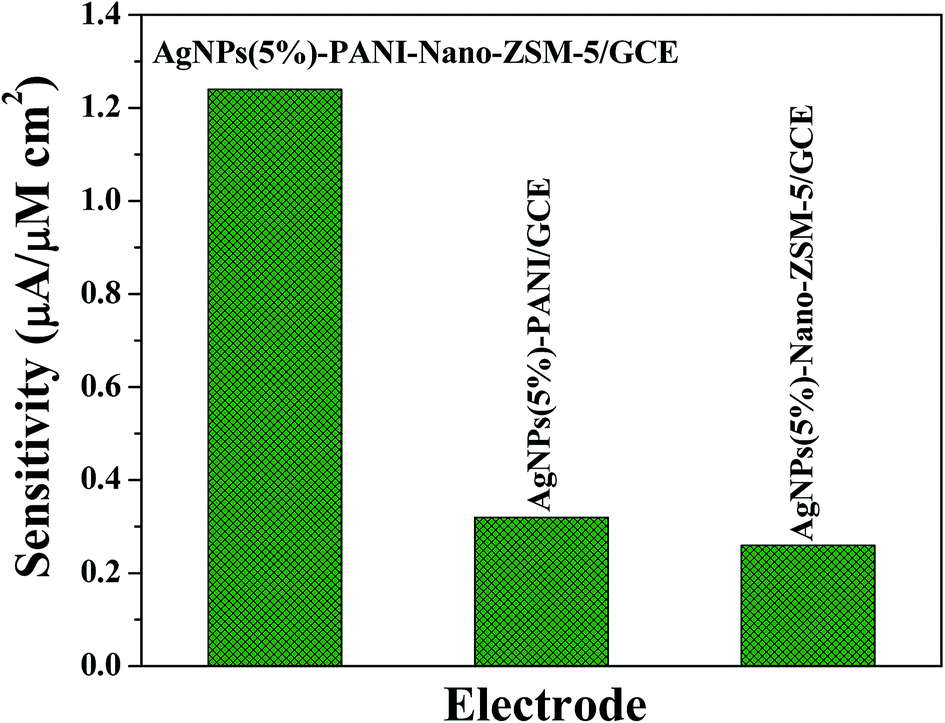 | ||
| Fig. 7 Comparison of the sensitivity at different modified glassy carbon electrodes investigated in this study towards lindane reduction. | ||
| S.No. | Modified electrode | Linear range (μM) | Limit of detection | Sensitivity (μA μM−1 cm−2) | Reference |
|---|---|---|---|---|---|
| a MIP = Molecular imprinted polymer, DPA = 9,10-diphenylanthracene, GCE = glassy carbon electrode. | |||||
| 1 | DPA | 40–100 | — | — | 28 |
| 2 | CuO/MnO2 modified GCE | 1–700 | 4.8 nM | 0.12 | 29 |
| 3 | NiCo2O4 modified GCE | 10–170 | 3.6 μM | 0.2 | 32 |
| 4 | MIP coated TiO2 nanotubes | 0.1–10 | 30 nM | — | 33 |
| 5 | Cellulose acetate modified GCE | 50–180 | 9.18 μM | — | 34 |
| 6 | AgNPs(5%)-PANI-Nano-ZSM-5/GCE | 0.01–900 | 5 nM | 1.24 | This work |
Reproducibility, stability, and anti-interference property of sensor
The reproducibility and stability of the developed sensor was evaluated in the sensing studies. Five AgNPs(5%)-PANI-Nano-ZSM-5/GCE were constructed and their current response to 50 μM concentration of lindane was investigated. The relative standard deviation (RSD) was found to be 2.4%, confirming that the fabrication method was highly reproducible. The stability of AgNPs(5%)-PANI-Nano-ZSM-5/GCE was examined by recording repetitive CVs for 50 scans at a scan rate 50 mV s−1 in the presence of lindane (50 μM). No obvious change in the peak current was observed after 50 cycles, which confirms that AgNPs(5%)-PANI-Nano-ZSM-5/GCE is highly stable. The long term stability of the sensor was evaluated by measuring its sensitivity in the presence of 50 μM lindane for 30 days. The sensor was stored in a refrigerator at 278 K when not in use and its sensitivity was tested at regular interval of 5 days. The sensor was reactivated by dipping in a supporting electrolyte for 30 min before the measurement. The results confirmed that the DPV response of the electrode for the same concentration of lindane remained almost the same with an RSD of 3.8%, indicating that the modified electrode has excellent stability and the developed sensor can be used for a long duration. To investigate the selectivity of AgNPs(5%)-PANI-Nano-ZSM-5/GCE toward lindane determination, an interference study was carried out in the presence of various interfering agents. The results indicate that organic compounds (5 mM each), such as chlorobenzene, 1,3,5-trichlorobenzene, 4-chlorobenzaldehyde, cyclohexane, and benzene, did not show any interference toward lindane detection (Fig. S7, ESI†). These results indicate that the developed sensor is specific to lindane.Determination of lindane in water samples
To show the practical application of the developed sensor, experiments were performed to determine the concentration of lindane in tap water and river water samples. The samples containing different amounts of lindane were prepared in 60:40 (v/v) methanol–tap water (10 mL) and the results are listed in Table 3. The values of recovery were in the range from 99% to 102%, suggesting the accuracy of AgNPs(5%)-PANI-Nano-ZSM-5/GCE based sensor. These results confirm that the proposed sensor is reliable and sensitive enough for the determination of lindane in different real water bodies.
Conclusions
In summary, a silver nanoparticle decorated polyaniline-zeolite nanocomposite material was synthesized. Scanning/transmission electron microscopy investigations confirmed that a polyaniline film was formed on the surface of Nano-ZSM-5 and no separate bulk polyaniline phase was formed. An electrochemical sensor based on silver nanoparticle decorated PANI-Nano-ZSM-5 modified glassy carbon electrode was fabricated for the nanomolar detection of lindane in an aqueous-methanol medium. The results demonstrated that the developed sensor exhibited high electro-catalytic activity, sensitivity, and stability toward lindane reduction. The high activity of AgNPs(5%)-PANI-Nano-ZSM-5 can be attributed to the synergistic contribution provided by highly dispersed Ag nanoparticles and the conductive PANI film at the high surface area of Nano-ZSM-5. The analytical performance of the developed sensor was extended in the determination of lindane in different water bodies with satisfactory results. The proposed methodology is simple, rapid and provides a potentially new analytical platform for the detection of lindane in ground water and other water bodies.Acknowledgements
Authors thank the Department of Science and Technology, New Delhi for financial assistance (DST grant SB/S1/PC-91/2012). BK is grateful to CSIR, New Delhi for SRF fellowship. Authors are also thankful to Director IIT Ropar for his constant encouragement.Reference
- M. E. Torres Padrón, Z. Sosa Ferrera and J. J. Santana Rodríguez, Anal. Bioanal. Chem., 2006, 386, 332–340 CrossRef PubMed.
- A. J. Durie, A. M. Z. Slawin, T. Lebl and D. ÓHagan, Angew. Chem., Int. Ed., 2012, 51, 10086–10088 CrossRef CAS PubMed.
- T. Phillips, A. Seech, H. Lee and J. Trevors, Biodegradation, 2005, 16, 363–392 CrossRef CAS PubMed.
- B. Rodríguez-Garrido, T. A. Lú-Chau, G. Feijoo, F. Macías and M. C. Monterrroso, Environ. Sci. Technol., 2010, 44, 7063–7069 CrossRef PubMed.
- J. C. Quintero, M. T. Moreira, G. Feijoo and J. M. Lema, Chemosphere, 2005, 61, 528–536 CrossRef CAS PubMed.
- K. L. Willett, E. M. Ulrich and R. A. Hites, Environ. Sci. Technol., 1998, 32, 2197–2207 CrossRef CAS.
- S. W. C. Chung and B. L. S. Chen, J. Chromatogr. A, 2011, 1218, 5555–5567 CrossRef CAS PubMed.
- H. A. Alegria, F. Wong, L. M. Jantunen, T. F. Bidleman, M. S. Figueroa, G. G. Bouchot, V. C. Moreno, S. M. Waliszewski and R. Infanzon, Atmos. Environ., 2008, 42, 8810–8818 CrossRef CAS PubMed.
- J. C. Harfield, C. Batchelor-McAuley and R. G. Compton, Analyst, 2012, 137, 2285–2296 RSC.
- M. Liu, S. He and W. Chen, Nanoscale, 2014, 6, 11769–11776 RSC.
- M. Govindhan, B.-R. Adhikari and A. Chen, RSC Adv., 2014, 4, 63741–63760 RSC.
- Y. Huang, Y.-E. Miao, S. Ji, W. W. Tjiu and T. Liu, ACS Appl. Mater. Interfaces, 2014, 6, 12449–12456 CAS.
- A. A. Isse, S. Gottardello, C. Durante and A. Gennaro, Phys. Chem. Chem. Phys., 2008, 10, 2409–2416 RSC.
- D. Lexa, J. M. Saveant, H. J. Schaefer, B. Su Khac, B. Vering and D. L. Wang, J. Am. Chem. Soc., 1990, 112, 6162–6177 CrossRef CAS.
- A. Klein, Y. H. Budnikova and O. G. Sinyashin, J. Organomet. Chem., 2007, 692, 3156–3166 CrossRef CAS PubMed.
- M. Stiles, J. Org. Chem., 1994, 59, 5381–5385 CrossRef CAS.
- A. A. Peverly, J. A. Karty and D. G. Peters, J. Electroanal. Chem., 2013, 692, 66–71 CrossRef CAS PubMed.
- A. A. Isse, A. De Giusti, A. Gennaro, L. Falciola and P. R. Mussini, Electrochim. Acta, 2006, 51, 4956–4964 CrossRef CAS PubMed.
- A. A. Isse, L. Falciola, P. R. Mussini and A. Gennaro, Chem. Commun., 2006, 344–346 RSC.
- B. Kaur, M. U. Anu Prathap and R. Srivastava, ChemPlusChem, 2012, 77, 1119–1127 CrossRef CAS PubMed.
- B. Kaur and R. Srivastava, Electroanalysis, 2014, 26, 1739–1750 CrossRef CAS PubMed.
- B. Kaur and R. Srivastava, Electrochim. Acta, 2014, 141, 61–71 CrossRef CAS PubMed.
- B. Kaur and R. Srivastava, Sens. Actuators, B, 2015, 211, 476–488 CrossRef CAS PubMed.
- M. U. Anu Prathap, B. Thakur, S. N. Sawant and R. Srivastava, Colloids Surf., B, 2012, 89, 108–116 CrossRef CAS PubMed.
- M. U. Anu Prathap, B. Kaur and R. Srivastava, J. Colloid Interface Sci., 2012, 381, 143–151 CrossRef CAS PubMed.
- P. Alexandridis and T. A. Hatton, Colloids Surf., A, 1995, 96, 1–46 CrossRef CAS.
- S. Xuan, Y.-X. J. Wang, K. C.-F. Leung and K. Shu, J. Phys. Chem. C, 2008, 112, 18804–18809 CAS.
- P. R. Birkin, A. Evans, C. Milhano, M. I. Montenegro and D. Pletcher, Electroanalysis, 2004, 16, 583–587 CrossRef CAS PubMed.
- M. U. Anu Prathap, S. Sun, C. Wei and Z. J. Xu, Chem. Commun., 2015, 51, 4376–4379 RSC.
- S. M. Kulikov, V. P. Plekhanov, A. I. Tsyganok, C. Schlimm and E. Heitz, Electrochim. Acta, 1996, 41, 527–531 CrossRef CAS.
- L. Falciola, A. Gennaro, A. A. Isse, P. R. Mussini and M. Rossi, J. Electroanal. Chem., 2006, 593, 47–56 CrossRef CAS PubMed.
- M. U. Anu Prathap and R. Srivastava, Electrochim. Acta, 2013, 108, 145–152 CrossRef CAS PubMed.
- P. Wang, L. Ge, M. Li, W. Li, L. Li, Y. Wang and J. Yu, J. Inorg. Organomet. Polym. Mater., 2013, 23, 703–711 CrossRef CAS.
- A. Kumaravel, S. Vincent and M. Chandrasekaran, Anal. Methods, 2013, 5, 931–938 RSC.
Footnote |
| † Electronic supplementary information (ESI) available: Additional details for the results and discussion as noted in the text, Fig. S1–S7, Scheme S1, and Table S1 with illustrations. Materials and instruments used are also provided. See DOI: 10.1039/c5ra09461e |
| This journal is © The Royal Society of Chemistry 2015 |