DOI:
10.1039/C5RA08903D
(Paper)
RSC Adv., 2015,
5, 67610-67616
Electrospun hollow ZnO/NiO heterostructures with enhanced photocatalytic activity†
Received
13th May 2015
, Accepted 3rd August 2015
First published on 3rd August 2015
Abstract
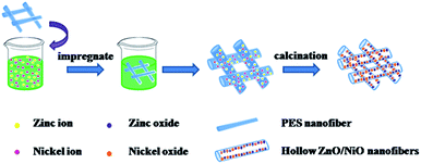
ZnO/NiO hollow nanofibers with high photocatalytic activity are successfully fabricated by impregnating electrospun polyethersulfone (PES) nanofiber webs in nickel acetate and zinc acetate solutions and subsequent thermal treatment. From scanning electron microscopy (SEM) and transmission electron microscopy (TEM) images, it can be observed that the morphology of the ZnO/NiO products is a hollow structure successively. According to statistics, the ZnO/NiO hollow nanofibers show diameters of approximate 414 nm with inner diameters of about 261 nm. Fourier transform infrared radiation (FTIR) and X-ray diffraction (XRD) measurements demonstrate that the product is composed of ZnO/NiO hollow nanofibers with hexangular structure ZnO and cubic structure NiO. The formation mechanism is studied in detail by TGA and DSC. The photocatalytic activity of the hollow ZnO/NiO heterojunction nanofibers for the degradation of methyl orange (MO) is much higher than that of pure ZnO and NiO nanofibers, which may be ascribed to the unique hollow structure and the highly efficient separation of photogenerated electron–hole pairs. Furthermore, the photocatalytic mechanism of the hollow ZnO/NiO nanofibers is expounded.
Introduction
Many kinds of semiconductor metal oxide-based nanocomposites, such as TiO2–SnO2,1 ZnO–SnO2,2 ZnO–TiO2,3 and so forth, have attracted much attention by scientific researchers from all over the world and are being widely utilized in the field of optoelectronics, gas sensors and various photocatalysts due to their unique optical, electronic, and photoactive properties.4–6 The fabrication of composite nanostructures based on the combination of semiconducting oxides offers a pivotal path to combining the different physical and chemical properties of individual components into one system.7 Zinc oxide (ZnO), as an n-type semiconductor (Eg = 3.2 eV), has high photosensitivity, high catalytic activity, suitable bandgap, and low cost.8,9 In the past several years, the composite semiconductors, which were formed by ZnO and other metal oxides such as TiO2, CuO, Cr2O3 and so on, had been reported.10–12 Among these composite materials, the ZnO/NiO composite materials have been intensively investigated that are applied as photocatalysts, gas sensors and electrical properties.13,14
In recent years, many efforts have been made to the fabrication of various semiconductors nanofibers, which include the chemical oxidative polymerization method,15 in situ deposition polymerization,16 the template method,17 hydrothermal synthesis,18 metal organic chemical vapor deposition,19 and so on. To the best of our knowledge, electrospinning technique, a versatile and mature method, has been exploited to manufacture nanofibers with controllable diameters, compositions and porosities. In terms of the fabrication for nanofibers, this method possesses the advantage of efficient composition control. In addition, according to recent literatures, poly(vinyl alcohol) (PVA),20 polyvinylpyrrolidone (PVP),21 polyaniline (PANI)22 are commonly used as polymer templates to fabricate the composite nanofibers by electrospinning method. Only the fibrous structure of composite can be obtained by these precursors. Notably, polyethersulfone (PES) can be considered as a new template for preparing inorganic composite nanofibers with special hollow structure since it has a good performance with thermal stability, hydrolysis resistance and chemical resistance.23 Unfortunately, there are rarely reports about using PES as template to prepare the composite materials, so it is worth researching further. Besides, among some composite materials, ZnO/NiO nanomaterials with special structure have attracted the most attention for application in photocatalysts, considering their low cost. Some reports point out that the ZnO/NiO composite materials have been applied to degrade nonbiodegradable dyes through photocatalytical routes.8 The superior functional performance of the ZnO/NiO semiconducting oxides is mainly attributed to the build-up of an inner electric field at the p/n junction interfere.7,24 The recombination of photogenerated electron–hole pairs can be effectively suppressed, thereby improving the efficiency of net charge transfer in the reaction process by fabricating composite nanostructures.25 However, in some case, ZnO/NiO composite materials with special structures, especially for hollow structure, may possess the excellent degradation efficiency of organic pollutants in photocatalytic activity, which impel us to further penetrate into its application.
In this work, the hollow ZnO/NiO nanofibers which were expected to have application in photocatalytic activity were prepared by impregnating electrospun polyethersulfone (PES) nanofibers webs in nickel acetate and zinc acetate solution and subsequent calcination. The structure and physicochemical property of the calcined samples were elucidated by TGA, DSC, SEM, TEM, FT-IR, XRD, EDX and DRS, respectively. In addition, the formation mechanism of the nanofibers structures was investigated. Whereafter, the photocatalytic activities of the as-prepared samples (hollow ZnO/NiO composite nanofibers; pure ZnO nanofibers and pure NiO nanofibers) were carried out in detail.
Experimental section
Chemicals and materials
Zinc acetate A.R. [Zn(CH3COO)2·2H2O] was purchased from Beijing Chemical Works Fine Chemicals Reagent Company, Beijing, China. Nickel(II) acetate tetrahydrate [Ni(CH3COO)2·4H2O] was provided by Sinopharm Chemical Regent Co., Ltd, China. Polyethersulfone (PES) was supplied by Changchun Jida plastic engineering research Co., Ltd, China. N,N-Dimethylformamide (DMF, Xilong Chemical Co., Ltd, China) and purified water (Wahaha Group) were used as solvent directly. All of these chemical reagents were analytical grade, without further purification.
Preparation of the n-type ZnO/p-type NiO nanofibers
Based on a typical procedure, the pale yellow electrospinning solution was prepared by dissolving PES in N,N-dimethylformamide (DMF) at a concentration of 34 wt%. After vigorous stirring at 80 °C for 24 hours, the precursor solution for electrospinning could be obtained. The polymer solution was charily sucked into the syringe with an internal diameter of 0.69 mm which was connected to a high-voltage power supply (Beijing Yongkang Industry Technology Development Co., Ltd, China). A piece of flat aluminum foil as the collector was placed at 26 cm away from the tip of the spinning nozzle. The applied high voltage was held at 13 kV and the feeding rate of the solution was controlled at 0.04 mm min−1 by means of a single syringe pump. Finally, a dense web of electrospun composite nanofibers was distributed uniformly over the collector. All experiments were carried out at ambient temperature. The fibers were subsequently exposed to the air overnight to remove the residual organic solvent.
3 g nickel acetate [Ni(CH3COO)2·4H2O] and 3 g zinc acetate [Zn(CH3COO)2·2H2O] were mixed with 100 mL purified water (add a little acetic acid) in a beaker under vigorous stirring for 2 h. Subsequently, the prepared PES nanofibers were immersed into the above solution for 2 days. After drying, the samples were calcinated at 800 °C in air with a heating rate of 5 °C min−1 for 3 h, and the n-type ZnO/p-type NiO nanofibers were successfully prepared. Moreover, to investigate the photocatalytic activity of the n-type ZnO/p-type NiO nanofibers in detail, pure ZnO and pure NiO nanofibers that can be used for comparison were prepared through the same experimental conditions.
Characterization
Thermal gravimetric analysis (TGA) was performed on a TG-DTG instrument (Beijing Hengjiu Instrument Ltd, Beijing, China) to determine the temperature of possible decomposition and crystallization of the nanofibers. Measurements were conducted from room temperature to 900 °C at a heating rate of 10 °C min−1 under a flowing air atmosphere. The surface morphology and dimension of the nanofibers were observed under scanning electron microscope (SEM) (SHIMDZU SSX-550, Japan) equipped with energy dispersive X-ray analysis (EDX) and transmission electron microscopy (TEM) (JEM-2100F, Japan). Before testing, the nanofibers were sputter coated with gold using ETD-2000 auto sputter coater (Elaborate Technology Development Co., Ltd, China) with a current of 4 mA for 2 min. Ground on the SEM images, the diameter of nanofibers was measured using image visualization software Image J. The crystalline structures of the calcined nanofibers were identified by the X-ray diffraction (XRD). XRD analysis was obtained using a Siemens D5005 XRD diffractometer in 2θ region of 20–80° with Cu Kα radiation. Fourier transform-infrared radiation (FT-IR) spectrometer (SHIMDZU, 1.50SU1, Japan) was used to identify the vibration in functional groups presented in the samples. The spectra were obtained with 20 scans per sample ranging from 4000 to 400 cm−1. UV-vis diffuse reflectance spectra (DRS) of the nanofibers were measured using a diffuse reflectance accessory of UV-vis spectrophotometer (DRS) (SHIMDZU UV-3600, Japan).
Photocatalytic activity measurement
The photocatalytic activities of the as-prepared samples (hollow ZnO/NiO composite nanofibers, pure ZnO nanofibers and pure NiO nanofibers) were evaluated by the photocatalytic degradation of a model pollutant, methyl orange (MO), under ultraviolet light irradiation. The reaction suspensions were prepared by adding the nanofibers photocatalyst (20 mg) into MO aqueous solution (40 mL, 10 mg L−1). The suspension was stirred in the dark for 1 h to obtain a fine dispersion and ensure the absorption–desorption equilibrium between the organic molecules and the catalyst surfaces. Then the solution was exposed to an ultraviolet (UV)-radiation lamp (UV-8, 12 W, 365 nm) irradiation whilst stirring at room temperature. At given time intervals, a few milliliters of solution were drawn from the mixture and centrifuged to separate the nanofibers. Afterwards, the solution was loaded into a UV-vis spectrophotometer (SHIMDZU UV-3600, Japan). In order to demonstrate the stability and usage of the catalysts, we recycled the used ZnO/NiO hollow nanofibers. The relative concentration of MO was monitored by comparing the characteristic absorption intensity at 464 nm with that of the original MO solution.22
Results and discussion
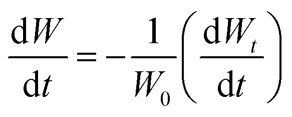
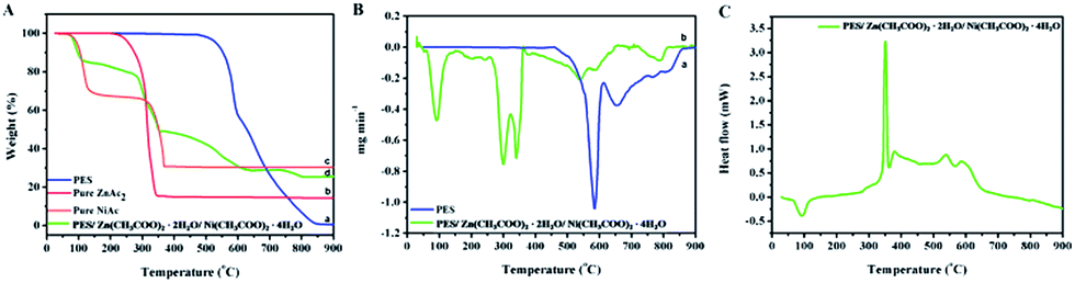
TGA curves of pure PES nanofibers, pure Zn(CH3COO)2·2H2O powders, pure Ni(CH3COO)2·4H2O powders and PES/Zn(CH3COO)2·2H2O/Ni(CH3COO)2·4H2O composite nanofibers were shown in Fig. 1A. Moreover, in order to see the weight loss range obviously, the DTG curves were displayed in Fig. 1B and the weight loss rate was calculated as below:26| |
 | (1) |
 |
| | Fig. 1 (A) TGA curves of thermal decomposition of (a) pure PES nanofibers; (b) pure Zn(CH3COO)2·2H2O powders; (c) pure Ni(CH3COO)2·4H2O powders and (d) PES/Zn(CH3COO)2·2H2O/Ni(CH3COO)2·4H2O composite nanofibers. (B) DTG curves of (a) pure PES nanofibers; (b) PES/Zn(CH3COO)2·2H2O/Ni(CH3COO)2·4H2O composite nanofibers. (C) DSC curves of PES/Zn(CH3COO)2·2H2O/Ni(CH3COO)2·4H2O composite nanofibers. | |
As observed in Fig. 1A(a) and B(a), the thermal decomposition process of pure PES nanofibers began from 480 °C. It was shown that the polyethersulfone was a good thermal stability polymer. The major weight loss of pure PES nanofibers occurred at 580 °C and 660 °C. This was consistent with nearly 100% mass loss in the range of 480–850 °C, which was corresponded to the decomposition of main chain of the PES. After 850 °C, no more weight loss can be seen, indicating that the PES was decomposed completely. The TGA curve of pure Zn(CH3COO)2·2H2O powders (Fig. 1A(b)) presented almost 85% total weight loss from 200 to 350 °C, which could be ascribed to the decomposition of the CH3COO group of zinc acetate.27 Additionally, the TGA curve of pure Ni(CH3COO)2·4H2O powders (Fig. 1A(c)) seemed to exhibit two steps of decomposition with a total weight loss of 70%. The first step appeared from 70 to 130 °C was attributed to part decomposition of Ni(CH3COO)2·4H2O and liberation of the crystal water. The second step, which occurred in the range of 300–370 °C, can be ascribed to the complete decomposition of Ni(CH3COO)2. As can be seen from Fig. 1A(d) and B(b), the PES/Zn(CH3COO)2·2H2O/Ni(CH3COO)2·4H2O composite nanofibers had four-step thermogram. Firstly, 15% weight loss had occurred below the 120 °C; secondly, there was a 36% weight loss between 120 and 370 °C; also, from 370 to 640 °C, there was a 20% weight loss; and finally, 5% weight loss existed in the temperature range of 740–800 °C. However, above 800 °C, there was no evident weight loss. Referring to the analyses above, the first step was mainly ascribed to part decomposition of Ni(CH3COO)2·4H2O and liberation of the crystal water, which showed dramatic weight loss approximate at 90 °C. The second step was attributed to the decomposition of zinc acetate and nickel acetate. The third step was resulted from the complete decomposition of acetate and degradation of the main chain of PES. The fourth step was related to the entirely removal of the organic constituents in the nanofibers. It has been reported that the existence of inorganic salt can be conducive to the decomposition of the polymer. When the temperature reached about 800 °C, the TGA curve was gentle, manifesting that the composite nanofibers had transformed into pure inorganic oxide entirely. Considering the complete decomposition of the PES nanofibers at high temperature, the increase of the residual mass amount after the TGA would correspond to the addition of the inorganic salt. This confirmed the presence of inorganic salt on the PES nanofibers.
DSC measurement was implemented in a range of room temperature to 900 °C in order to prove the existence of various substances and evaluate their thermal behavior. As observed in the DSC curve (Fig. 1C), the endothermic peak appeared at 100 °C, which could be attributed to the loss of moisture and the melt of Ni(CH3COO)2. The sharp exothermic peak at 350 °C corresponded to the decomposition of acetate. Meanwhile, the broad exothermic peaks at about 380 °C, 540 °C and 595 °C in the DSC curve were thought to the continued decomposition of acetate and degradation of main chain from PES. All the above DSC analyses could be confirmed by an obvious weight loss in the TGA curve at the corresponding temperature range from 25 °C to 900 °C.
Exemplary scanning electron microscope (SEM) micrographs of PES nanofibers and PES/Zn(CH3COO)2·2H2O/Ni(CH3COO)2·4H2O composite nanofibers were depicted in Fig. 2(a) and (b). As shown in Fig. 2(a), the electrospun PES nanofibers formed network structure and appeared to be relatively smooth and homogeneous surface due to the polymeric property. According to Gaussian fitting and statistics, the mean diameter of randomly oriented nanofibers was 387 nm. After immersing in a mixture of zinc acetate and nickel acetate solution, it could be seen that the outer layer of PES nanofibers was evenly filled with zinc acetate and nickel acetate so that the surface of the nanofibers became rough [Fig. 2(b)]. After statistics, the mean diameter of the nanofibers was 556 nm which was slightly increased. This might be ascribed to the expansion of PES nanofibers and the adsorption of inorganic salts around the nanofibers during the process of immersion. The SEM images of the sintered products were shown in Fig. 2(c)–(e). Surprisingly, the ZnO/NiO heterojunction nanofibers exhibited a hollow microstructure. From the perspective of the surface vertical view [Fig. 2(c)], it could be seen that the surface of these randomly oriented nanofibers was rough after calcination at 800 °C, and the mean diameter of the hollow ZnO/NiO heterojunction nanofibers was approximately 414 nm. In Fig. 2(d), the ruptured sections clearly showed the hollow structure of ZnO/NiO heterojunction nanofibers. In addition, Fig. 2(e) showed the typical SEM images of the above ZnO/NiO hollow nanofibers taken at high magnification. A large quantity of hollow nanofibers with nearly uniform diameter could be clearly seen in Fig. 2(e). According to the statistics, the inner diameter of the hollow nanofibers was approximate 261 nm. Since this special hollow structure was formed, the contact area of prepared ZnO/NiO heterojunction nanofibers was increased, which could improve the application of photocatalytic activity. In order to further study the microstructure of the ZnO/NiO hollow nanofibers, transmission electron microscopy (TEM) observation was carried out. As shown in Fig. 2(f), the ZnO/NiO nanofibers possessed a hollow structure. It can be seen clearly that the hollow nanofibers were composed of nanoparticles and the rough surface linked with ZnO and NiO nanoparticles. The energy-dispersive X-ray (EDX) spectra [Fig. 2(g)] confirmed that the heterojunction nanofibers were composed of Zn, Ni, and O, which was consistent with the XRD results. In addition, the weight percentage and the atomic percentage of Zn, Ni, O elements in this structure were calculated, respectively.
 |
| | Fig. 2 SEM micrographs of (a) pure PES nanofibers; (b) PES nanofibers immersed in a mixture of Zn(CH3COO)2·2H2O and Ni(CH3COO)2·4H2O solutions for 2 days; ZnO/NiO hollow nanofibers from different positions (c) vertical view of the surface; (d) cross section of the surface; (e) cross section of the partial surface at high magnification; and their corresponding diameter distribution; (f) TEM image of the ZnO/NiO hollow nanofibers; (g) EDX spectrum of the ZnO/NiO hollow nanofibers. | |
The formation mechanism of the hollow ZnO/NiO heterojunction nanofibers can be explained as follow. The prepared PES nanofibers via electrospinning were impregnated into the Zn(CH3COO)2·2H2O and Ni(CH3COO)2·4H2O mixed solution. Due to soaking for a long time, the Zn2+ and Ni2+ were evenly adsorbed on the surface of PES nanofibers. In the subsequent heating treatment, the inorganic salts were decomposed first compared to the PES nanofibers from the TGA curves (Fig. 1(A)). At the same time, the Zn2+ and Ni2+ were slowly oxidized into the ZnO and NiO. With the extension of heating time and the increase of heating temperature, the PES nanofibers were gradually degraded. Ultimately, the inner layer organic constituents were entirely removed and the metal oxides were connected together and formed of the hollow ZnO/NiO heterojunction nanofibers. The schematic of possible formation process was shown in Fig. 3.
 |
| | Fig. 3 Formation mechanism of hollow ZnO/NiO composite nanofibers. | |
The X-ray diffraction (XRD) patterns of the as-obtained nanofibers were shown in Fig. 4. It could be seen from Fig. 4(a) that all the diffraction peaks could be indexed from the (111), (200), (220), (311), (222) planes of the cubic structure for NiO (JCPDF-73-1523). The Fig. 4(b) with typical characteristic peaks such as (100), (002), (101), (102), (110), (103), (112), (201), (202) corresponded to hexagonal wurtzite structure of ZnO (JCPDF-75-0576). As shown in Fig. 4(c), there are 14 main diffraction peaks corresponding to (100), (002), (101), (111), (200), (102), (110), (220), (103), (112), (201), (311), (202), (222) planes at 31.898°, 34.578°, 36.393°, 37.169°, 43.168°, 47.679°, 56.731°, 62.609°, 62.988°, 68.072°, 69.208°, 75.196°, 77.082° and 79.158°, respectively. Therefore, the hollow ZnO/NiO heterojunction nanofibers had two crystalline phases of both cubic structure NiO and hexagonal structure ZnO simultaneously, no characteristic peaks for impurity were observed. Notably, the sharp and small values of the full widths at half maxima (FWHM) of the diffraction peaks revealed that the hollow ZnO/NiO composite nanofibers were of high crystallinity.28 The results of XRD patterns further confirmed that the calcination temperature of 800 °C was sufficient to remove PES completely and formed the two oxides.
 |
| | Fig. 4 XRD patterns of (a) pure NiO nanofibers; (b) pure ZnO nanofibers; (c) ZnO/NiO hollow nanofibers. | |
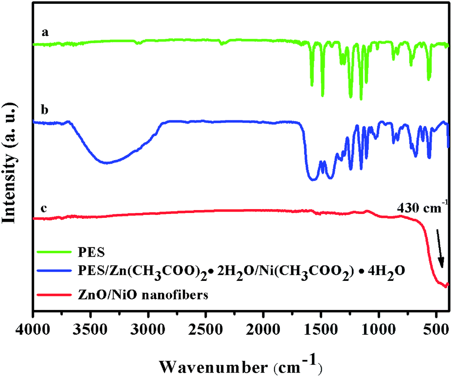
FTIR spectrum was also performed to identify the structure of the obtained nanofibers, which was shown in Fig. 5. As expected, the prepared pure PES nanofibers [Fig. 5(a)] showed typical aromatic bands at 1580, 876, 716, 560 cm−1 from the benzene ring with one or more substitutes. Furthermore, the absorption peaks located at about 1485, 1245, 1150 cm−1 were corresponding to C–C stretching vibration, aromatic ether band and aromatic sulfone band, respectively.29,30 Fig. 5(b) depicted the spectrum of the PES/Zn(CH3COO)2·2H2O/Ni(CH3COO)2·4H2O blend nanofibers and it was the same as Fig. 5(a). Notably, the broad band at about 3400 cm−1 was assigned to the O–H asymmetrical stretching vibration, which came from H2O in Ni(CH3COO)2·4H2O and Zn(CH3COO)2·2H2O. When the nanofibers were annealed at 800 °C [Fig. 5(c)], the representative absorption peaks, which belonged to the organic groups of the polymer, disappeared and a new intense broadband at about 430 cm−1 came out. This band assigned to the Zn–O vibration of hexagonal ZnO and Ni–O vibration of cubic NiO appeared but overlapped,31,32 indicating that the nanofibers obtained at this high temperature were pure inorganic species of ZnO/NiO. The results accorded well with XRD and EDX analysis.
 |
| | Fig. 5 FTIR spectra of (a) pure PES nanofibers; (b) PES/Zn(CH3COO)2·2H2O/Ni(CH3COO)2·4H2O composite nanofibers (c) ZnO/NiO hollow nanofibers. | |
Fig. 6A showed the UV-vis diffuse reflectance (DR) spectroscopy of the pure NiO, pure ZnO and hollow ZnO/NiO nanofibers. In Fig. 6A(a) and (c), the strong absorption peaks of the as-electrospun NiO and ZnO nanofibers appeared at 315 and 365 nm, respectively.28,33 Furthermore, the weak absorption peak with a maximum at 720 nm was observed in NiO nanofibers, which could be considered as intra-3d transitions of Ni2+ in the cubic crystal field of NiO.28 As observed in Fig. 6A(b), all of the absorption bands existed in the UV-vis DR spectroscopy of the hollow ZnO/NiO nanofibers, which were ascribed to the characteristic absorption of ZnO and NiO. It was confirmed that the hollow ZnO/NiO nanofibers were composite materials that were consisted of ZnO and NiO. The band-gap values of ZnO and NiO were calculated based on the well-established equation α = A(hv − Eg)1/2/hv, where α, v, Eg, and A were the absorption coefficient, light frequency, band gap energy, and a constant, respectively.8 As observed in Fig. 6B and C, the band gap of ZnO was evaluated to be 3.15 eV, while the band gap of NiO was found to be about 3.32 eV.
 |
| | Fig. 6 (A) UV-vis diffuse reflectance (DR) spectra of (a) NiO nanofibers; (b) ZnO nanofibers; (c) hollow ZnO/NiO nanofibers; (B and C) the plots of the (αhv)2 vs. photon energy (hv) for ZnO and NiO nanofibers, respectively. | |
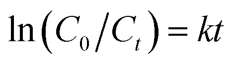
To identify the photocatalytic performance of the hollow ZnO/NiO heterojunction nanofibers for the degradation of organic pollutions, we carried out experiments of the photocatalytic degradation of methyl orange (MO) as a text reaction. The decrease of the absorption band intensities of the dyes indicated that MO had been degraded by UV light irradiation, catalyzed by ZnO/NiO nanocomposites. The time-dependent UV-vis spectra of MO during the irradiation were illustrated in Fig. 7(A). One can see that the characteristic peak of MO at 464 nm that was associated with the azo band (–N![[double bond, length as m-dash]](https://www.rsc.org/images/entities/char_e001.gif) N–) gradually disappeared after 150 min under UV light irradiation in the presence of ZnO/NiO hollow nanofibers.8 Furthermore, in the comparative experiments, the pure ZnO nanofibers and pure NiO nanofibers were used as a photocatalytic reference to investigate the photocatalytic activity of the hollow ZnO/NiO nanofibers. The degradation profiles of the same amount of different catalysts were shown in Fig. 7(B). The degradation efficiencies of MO after 150 min irradiation were about 40%, 76.5%, 91.89% for pure NiO, pure ZnO and the ZnO/NiO hollow nanofibers, respectively. An obvious degradation of MO was observed under UV light in the presence of the ZnO/NiO hollow nanofibers. Notably, the ZnO/NiO hollow nanofibers exhibited the highest photocatalytic activity as compared with both pure ZnO and pure NiO nanofibers, which might be attributed to the ZnO/NiO nanofibers unique hollow structure. The result might be favorable to the reaction with MO, leading to an excellent photocatalytic property. For a better comparison of the photocatalytic efficiency of the above electrospun nanofibers, the kinetics analysis of degradation of MO under UV light irradiation was also investigated. The kinetic linear simulation curves of the photocatalytic degradation of MO over the above nanofibers photocatalysts showed that the photocatalytic degradation process followed the first-order kinetics.34,35 The explanation was described below:
N–) gradually disappeared after 150 min under UV light irradiation in the presence of ZnO/NiO hollow nanofibers.8 Furthermore, in the comparative experiments, the pure ZnO nanofibers and pure NiO nanofibers were used as a photocatalytic reference to investigate the photocatalytic activity of the hollow ZnO/NiO nanofibers. The degradation profiles of the same amount of different catalysts were shown in Fig. 7(B). The degradation efficiencies of MO after 150 min irradiation were about 40%, 76.5%, 91.89% for pure NiO, pure ZnO and the ZnO/NiO hollow nanofibers, respectively. An obvious degradation of MO was observed under UV light in the presence of the ZnO/NiO hollow nanofibers. Notably, the ZnO/NiO hollow nanofibers exhibited the highest photocatalytic activity as compared with both pure ZnO and pure NiO nanofibers, which might be attributed to the ZnO/NiO nanofibers unique hollow structure. The result might be favorable to the reaction with MO, leading to an excellent photocatalytic property. For a better comparison of the photocatalytic efficiency of the above electrospun nanofibers, the kinetics analysis of degradation of MO under UV light irradiation was also investigated. The kinetic linear simulation curves of the photocatalytic degradation of MO over the above nanofibers photocatalysts showed that the photocatalytic degradation process followed the first-order kinetics.34,35 The explanation was described below:
| |
 | (2) |
where
k (min
−1) is the degradation rate constant,
C0 is the concentration of MO at adsorption equilibrium and
Ct is the concentration of MO at a time different intervals. To calculate reaction rate constant for the photodegradation of MO with different catalysts, the linear relationship between ln(
C0/
Ct) and the reaction time was summarized in
Fig. 7(C). It was indicated that the order of rate constant was ZnO/NiO hollow nanofibers > pure ZnO nanofibers > pure NiO nanofibers, which was consistent with the activity studies above. To prove the possibility of recyclability of the ZnO/NiO nanofibers, cycle experiments were performed. As can be seen from
Fig. 7(D), the photocatalytic activity of the ZnO/NiO nanofibers for the degradation of MO still kept above 80 percentage of the high level even recycle five times. With the increase number of repeated use, a small amount of the loss in process of recycle was the main reason for the slight lower photocatalytic efficiency than before. Therefore, the recyclability of the hollow ZnO/NiO heterojunction nanofibers was possible.
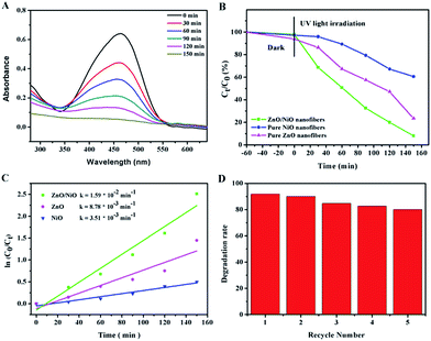 |
| | Fig. 7 (A) Adsorption spectra of MO solutions in the presence of ZnO/NiO hollow nanofibers under UV light at different periods of time; (B) photocatalytic degradation of MO concentration changes as a function of irradiation times after added different photocatalysis; (C) kinetic linear simulation curves of MO photocatalytic degradation with different electrospun nanofibers: (a) NiO nanofibers; (b) ZnO nanofibers; (c) ZnO/NiO hollow nanofibers; (D) the diagram of degradation ratio of MO versus recycle number with the ZnO/NiO hollow nanofibers. | |
The high photocatalytic activity of the hollow ZnO/NiO heterojunction nanofibers for MO decolorization was primarily due to electron–hole pair recombination inhibition by charge transfer processes. Fig. 8 showed the proposed energy band structure diagram of the hollow ZnO/NiO heterojunction photocatalysts. When the ZnO/NiO heterojunction was formed, the electron transfer occurred from ZnO to NiO while the holes transfer occurred from NiO to ZnO until the system obtained equalization. When the ZnO/NiO photocatalysts were irradiated by UV light with photon energy higher than or equal to the band gaps of ZnO and NiO, the electrons (e−) in the valence band (VB) could be excited to the conduction band (CB) with simultaneous generation of the same amount of holes (h+) in the VB (eqn (3)). On account of the ZnO was lower than that of NiO, upon light-activation the electron transfer from the CB of NiO to that of ZnO.36 The semiconductor NiO can act as a sink for photogenerated holes, making charge separation more efficient and thus suppressing recombination processes.8 Conversely, the photogenerated holes transfer could take place from the VB of ZnO to the VB of the NiO, suggesting that the photogenerated electrons and holes were efficiently separated (eqn (4)). The photogenerated electrons and holes in the ZnO/NiO photocatalysts could inject into a reaction medium and participate in chemical reactions.7
| |
 | (3) |
| | |
ZnO (e−, h+) + NiO (e−, h+) → NiO (h+) + ZnO (e−)
| (4) |
| | |
O2˙− + H2O → HO2˙ + OH−
| (6) |
| | |
HO2˙ + H2O → H2O2 + OH˙
| (7) |
| | |
H2O2 + e− → OH˙ + OH−
| (8) |
| | |
H2O2 + O2˙− → OH˙ + OH− + O2
| (9) |
| | |
OH˙ + MO → intermediates → CO2 + H2O
| (10) |
 |
| | Fig. 8 Schematic representation of the proposed energy band structure of the hollow ZnO/NiO heterojunction photocatalysts. | |
Under the UV light irradiation, the photogenerated electrons moved to the ZnO side, meanwhile, the photogenerated holes moved to the NiO side. The electronic acceptors like oxygen could easily trap the photogenerated electron (e−) to produce a superoxide anion radical (O2˙−). The formed O2˙− were reacted with absorbed H2O to produce H2O2, which would provide hydroxyl radical (OH˙) by acting as a direct electron acceptor by reaction with e− and O2˙− (eqn (5)–(9)). The hydroxyl radical (OH˙) was an extremely strong oxidant for decomposing the organic dyes (eqn (10)).33,37,38
Conclusions
In this work, by using the electrospinning technology and physical adsorption, the ZnO/NiO heterojunction nanofibers with hollow structure were successfully fabricated. Initially, the electrospun PES nanofibers had smooth surfaces with diameter of 387 nm. Then the PES nanofibers webs were impregnated in a mixture of zinc acetate and nickel acetate solutions and subsequently calcinated in air for 3 h, which induced the formation of ZnO/NiO hollow nanofibers. After statistics, the ZnO/NiO hollow nanofibers showed diameters of approximate 414 nm with the inner diameters of about 261 nm. The calcined ZnO/NiO heterojunction nanofibers were characterized by TGA, DSC, SEM and TEM techniques. Therefore, the formation mechanism of the nanofibers was confirmed. Moreover, the photocatalytic performance test indicated that the ZnO/NiO hollow nanofibers exhibited higher photocatalytic activity than the pure ZnO and NiO nanofibers for the degradation of MO dye under UV light irradiation, which might be attributed to the highly efficient separation of photogenerated electron–hole pairs. Therefore, we believe that the ZnO/NiO hollow nanofibers with high photocatalytic activity can be considered as a promising photocatalyst for dyes treatment. Also, it is expected that the hollow ZnO/NiO heterojunction nanofibers may possess greatly potential in the sensor areas and other fields for further research.
Acknowledgements
The Project 2015082 supported by Graduate Innovation Fund of Jilin University.
Notes and references
- Z. Liu, D. D. Sun, P. Guo and J. O. Leckie, Nano Lett., 2006, 7, 1081 CrossRef PubMed.
- J. S. Lee, O. S. Kwon and J. Jang, J. Mater. Chem., 2012, 22, 14565 RSC.
- B. Liu, Y. Sun, D. Wang, L. Wang, L. Zhang, X. Zhang, Y. Lin and T. Xie, RSC Adv., 2014, 4, 32773 RSC.
- S. Wang, D. Chao, E. B. Berda, X. Jia, R. Yang, X. Wang, T. Jiang and C. Wang, RSC Adv., 2013, 3, 4059 RSC.
- J. Zhao, L. Wang, X. Yan, Y. Yang, Y. Lei, J. Zhou, Y. Huang, Y. Gu and Y. Zhang, Mater. Res. Bull., 2011, 46, 1207 CrossRef CAS PubMed.
- M. A. Kanjwal, F. A. Sheikh, N. A. M. Barakat, I. S. Chronakis and H. Y. Kim, Appl. Surf. Sci., 2011, 257, 7975 CrossRef CAS PubMed.
- Y. Liu, G. Li, R. Mi, C. Deng and P. Gao, Sens. Actuators, B, 2014, 191, 537 CrossRef CAS PubMed.
- F. Tian and Y. Liu, Scr. Mater., 2013, 69, 417 CrossRef CAS PubMed.
- P. Singh, K. Mondal and A. Sharma, J. Colloid Interface Sci., 2013, 394, 208 CrossRef CAS PubMed.
- W. Wang, Z. Li, W. Zheng, H. Huang, C. Wang and J. Sun, Sens. Actuators, B, 2010, 143, 754 CrossRef CAS PubMed.
- Z. L. Liu, J. C. Deng, J. J. Deng and F. F. Li, Mater. Sci. Eng., B, 2008, 150, 99 CrossRef CAS PubMed.
- Y. Wang, S. Zhu, X. Chen, Y. Tang, Y. Jiang, Z. Peng and H. Wang, Appl. Surf. Sci., 2014, 307, 263 CrossRef CAS PubMed.
- M. Xiao, Y. Lu, Y. Li, H. Song, L. Zhu and Z. Ye, RSC Adv., 2014, 4, 34649 RSC.
- H. Pang, Y. Ma, G. Li, J. Chen, J. Zhang, H. Zheng and W. Du, Dalton Trans., 2012, 13284 RSC.
- K. R. Reddy, H. M. Jeong, Y. Lee and A. V. Raghu, J. Polym. Sci., Part A: Polym. Chem., 2010, 48, 1477 CrossRef CAS PubMed.
- K. R. Reddy, M. Hassan and V. G. Gomes, Appl. Catal., A, 2015, 489, 1 CrossRef CAS PubMed.
- P. Song, Q. Wang, Z. Zhang and Z. Yang, Sens. Actuators, B, 2010, 147, 248 CrossRef CAS PubMed.
- X. Zhou, C. Wang, W. Feng, P. Sun, X. Li and G. Lu, Mater. Lett., 2014, 120, 5 CrossRef CAS PubMed.
- S. L. Wang, X. Jia, P. Jiang, H. Fang and W. H. Tang, J. Alloys Compd., 2010, 502, 118 CrossRef CAS PubMed.
- M. A. Kanjwal, N. A. M. Barakat, F. A. Sheikh, M. S. Khil and H. Y. Kim, J. Mater. Sci., 2008, 43, 5489 CrossRef CAS.
- J. Moon, J.-A. Park, S.-J. Lee, S. C. Lim and T. Zyung, Curr. Appl. Phys., 2009, 9, S213 CrossRef PubMed.
- K. R. Reddy, K. Nakata, T. Ochiai, T. Murakami, D. A. Tryk and A. Fujishima, J. Nanosci. Nanotechnol., 2010, 10, 7951 CrossRef CAS PubMed.
- J. F. Li, Z. L. Xu, H. Yang, L. Y. Yu and M. Liu, Appl. Surf. Sci., 2009, 255, 4725 CrossRef CAS PubMed.
- J. Li, H. Fan, X. Jia, W. Yang and P. Fang, Appl. Phys. A: Mater. Sci. Process., 2009, 98, 537 CrossRef.
- A. Hameed, T. Montini, V. Gombac and P. Fornasiero, Photochem. Photobiol. Sci., 2009, 8, 677 CAS.
- M. Liu, Y. Wang, Z. Cheng, M. Zhang, M. Hu and J. Li, Appl. Surf. Sci., 2014, 313, 360 CrossRef CAS PubMed.
- Z. Zhang, X. Li, C. Wang, L. Wei, Y. Liu and C. Shao, J. Phys. Chem. C, 2009, 113, 19397 CAS.
- Z. Zhang, C. Shao, X. Li, C. Wang, M. Zhang and Y. Liu, ACS Appl. Mater. Interfaces, 2010, 2, 2915 CAS.
- M. Peyravi, A. Rahimpour, M. Jahanshahi, A. Javadi and A. Shockravi, Microporous Mesoporous Mater., 2012, 160, 114 CrossRef CAS PubMed.
- S. Saedi, S. S. Madaeni, K. Hassanzadeh, A. A. Shamsabadi and S. Laki, J. Ind. Eng. Chem., 2014, 20, 1916 CrossRef CAS PubMed.
- G. Xiong, U. Pal, J. G. Serrano, K. B. Ucer and R. T. Williams, Phys. Status Solidi C, 2006, 3, 3577 CrossRef CAS PubMed.
- R. Cerc Korošec, P. Bukovec, B. Pihlar and J. Padežnik Gomilšek, Thermochim. Acta, 2003, 402, 57 CrossRef.
- Z. Y. Zhang, C. L. Shao, X. H. Li, L. Zhang, H. M. Xue, C. H. Wang and Y. C. Liu, J. Phys. Chem. C, 2010, 114, 7920 CAS.
- N. Soltani, E. Saion, W. Mahmood Mat Yunus, M. Navasery, G. Bahmanrokh, M. Erfani, M. R. Zare and E. Gharibshahi, Sol. Energy, 2013, 97, 147 CrossRef CAS PubMed.
- S. Khanchandani, S. Kundu, A. Patra and A. K. Ganguli, J. Phys. Chem. C, 2013, 117, 5558 CAS.
- R. Liu, Y. Huang, A. Xiao and H. Liu, J. Alloys Compd., 2010, 503, 103 CrossRef CAS PubMed.
- I. M. Arabatzis, T. Stergiopoulos, M. C. Bernard, D. Labou, S. G. Neophytides and P. Falaras, Appl. Catal., B, 2003, 42, 187 CrossRef CAS.
- K. Rajeshwar, M. E. Osugi, W. Chanmanee, C. R. Chenthamarakshan, M. V. B. Zanoni, P. Kajitvichyanukul and R. Krishnan-Ayer, J. Photochem. Photobiol., C, 2008, 9, 171 CrossRef CAS PubMed.
Footnote |
| † Electronic supplementary information (ESI) available. See DOI: 10.1039/c5ra08903d |
|
| This journal is © The Royal Society of Chemistry 2015 |
Click here to see how this site uses Cookies. View our privacy policy here.