Enhanced electrocatalytic activity of nitrogen-doped multi-walled carbon nanotubes towards the oxygen reduction reaction in alkaline media
Merilin Vikkiska,
Ivar Kruusenberga,
Sander Ratsoa,
Urmas Joostb,
Eugene Shulgab,
Ilmar Kinkb,
Protima Rauwelb and
Kaido Tammeveski*a
aInstitute of Chemistry, University of Tartu, Ravila 14a, 50411 Tartu, Estonia. E-mail: kaido@chem.ut.ee; Tel: +372-7375168; Fax: +372-7375181
bInstitute of Physics, University of Tartu, Ravila 14c, 50411 Tartu, Estonia
First published on 29th June 2015
Abstract
In this work multi-walled carbon-nanotubes (MWCNTs) were doped with nitrogen using cyanamide (CM) or dicyandiamide (DCDA). To incorporate nitrogen into the CNT structure, high-temperature pyrolysis in an inert atmosphere was performed. For surface characterisation of nitrogen-doped CNTs (NCNTs) X-ray photoelectron spectroscopy (XPS), Raman spectroscopy, scanning electron microscopy (SEM) and transmission electron microscopy (TEM) were used. According to the results of XPS analysis, nitrogen was successfully incorporated into the carbon nanotube network. The electrocatalytic activity of NCNT catalysts for oxygen reduction reaction (ORR) in alkaline media was examined using the rotating disk electrode (RDE) and linear sweep voltammetry (LSV) measurements. The NCNT-DCDA material showed a better ORR performance than the NCNT-CM catalyst. The RDE results reveal that the NCNT materials studied could be considered as interesting alternatives to Pt-based catalysts in alkaline membrane fuel cells.
1. Introduction
Fossil fuels are presently dominant sources of energy. However, since these are non-renewable resources there is an urgent need to put into practice new renewable, environmentally friendly sources of energy. A fuel cell is an electrochemical energy conversion device,1,2 which affects the environment minimally.3 Until now the largest drawbacks of fuel cells are high cost, low durability4,5 and sluggish oxygen reduction reaction (ORR) on the cathode.4,6,7 There are different pathways for oxygen reduction: two, four or two-by-two electron transfer.8 Electrocatalysts are used to improve the kinetics of the ORR and the most active catalysts are Pt-based materials,2,3 which facilitate the four-electron reduction pathway, producing less hydrogen peroxide.9 However, Pt has disadvantages: it is expensive,4,5,10 tends to dissolve and agglomerate,4,11,12 has limited availability, suffers from CO and methanol poisoning.9 For these reasons, the Pt usage is becoming minimal and non-precious metal catalysts for ORR are being researched and developed.Many carbon materials such as carbon black, ordered mesoporous carbon, carbon nanotubes and nanofibers, graphite and graphene have been studied for sustainable energy conversion and storage.1,10,13 Carbon-based materials exhibit several useful properties like high surface area, high conductivity, high chemical and mechanical stability,1 low cost and tailorable surface chemistry.3,10,13–15 For these reasons carbon nanomaterials can find application in fuel cells, solar cells, supercapacitors and lithium-ion batteries.10,13 The electrocatalytic activity of nanocarbons towards the ORR can potentially reach the activity of Pt/C catalysts10,16 by doping with heteroatoms such as N, B, P, S and Se.1 Nitrogen-containing compounds used as precursor materials for N-doping are widely available,8 therefore nitrogen is most widely used as a doping agent among these choices. A great deal of attention has been paid to carbon nanotubes (CNTs) as catalysts or support materials in ORR electrocatalysis.8,17 Both single-walled (SWCNTs) and multi-walled carbon nanotubes (MWCNTs) have large specific surface area and good electrical conductivity.18,19 CNTs are cylindrical graphene layers consisting of six-atom carbon aromatic rings, where π electrons are delocalised and can give nucleophilic attack, which makes the carbon a Lewis base.20 The electrochemical stability of CNTs depends on the degree of graphitisation, as they are more stable, if the percentage of graphitisation is higher.21 Despite that CNTs show many unique properties and enhanced performance by implanting N atoms into the carbon lattice,22–25 onto the carbon basal plane or edge sites.
Nitrogen atom has a similar size to a carbon atom, which prevents significant lattice distortion, when the latter is substituted in carbon material.8 Various nitrogen-containing compounds have been used for N-doping and different N contents have been obtained. For example, xylene or pyridine have been used for nitrogen doping26–28 and 7.4% N content has been reported.29 With melamine even 20% N content with altered CNT structure and larger diameter was obtained.8,30–32 In addition to these precursors also polyaniline,33,34 ammonia,35,36 ethylenediamine,37,38 imidazole,39 urea40,41 and even ionic liquids42 have been used. Using nitrogen for the preparation of metal-free NCNTs has shown that N strongly promotes the carbon nanotube formation, without the necessity of metal catalysts,43 which is another advantage of N-doping.
Nitrogen-doped carbons and Pt catalysts possess different ORR mechanism, whereas nitrogen as an n-type dopant polarises the adjacent carbon atoms,44 but Pt catalysts use d-bands filling at O2 adsorption sites.44 If the nitrogen content increases then the oxygen adsorption is energetically more favourable and the ORR activity is enhanced.13,45 The amount and type of the incorporated N depend on few aspects: percentage of N in the precursor,46 the nitrogen precursor's content in the synthesis mixture,47 the temperature and the duration of heat-treatment.48 During the nitrogen doping the carbon atoms in sp2 configuration are substituted,1 achieved by post-treating the carbon material with nitrogen precursor49 or during the preparation of carbon materials.50,51 The ORR activity of N-doped carbon materials is improved due to nitrogen functionalities that are incorporated into the nanocarbon structure and edge plane defects that act as active sites.20 NCNTs have low stability in acidic media because of the hydrogen peroxide generated during the oxygen reduction reaction, which attacks the active sites,37 but in alkaline media the ORR activities similar to that of Pt have been obtained.52
There are four main N-functionalities on NCNTs: quaternary-N, pyridinic-N, pyrrolic-N and pyridine-N-oxide.53,54 Quaternary and pyridinic-N group are said to improve the ORR activity of NCNTs in alkaline media,13 but pyrrolic-N type is claimed to have negative effects.55 Pyridinic and pyrrolic-N do not donate the electrons into the delocalised π-system, but quaternary-N has the same configuration as carbon and donates extra electrons.1 Nitrogen incorporation makes the carbon more basic, possibly due to the electrons donated to the carbon framework by the N atoms, thus creating active sites, which improves the O2 adsorption and therefore enhances the electrocatalytic activity for ORR.56 The physico-chemical origin of the ORR activity is still not exactly understood. Some groups state that it is the quaternary-N,57 which serves as an active site due to reduced adsorption energy,3 but others that pyridinic-N together with small pores on the catalyst improve the ORR kinetics.58 In addition to this, there are hidden parameters of CNTs such as the number of tube walls, tube length and diameter that might affect the electrocatalytic activity for ORR.43 Despite that NCNTs as metal-free ORR catalysts have many advantages compared to Pt, their active site density is low, which might affect the fuel cell performance over a period of time.59
Recently, we have studied the reduction of oxygen on nitrogen-doped graphene catalysts.60 In this work nitrogen-doped CNTs were synthesised using two different nitrogen precursors: cyanamide (CM) and dicyandiamide (DCDA). CM and DCDA are simple nitrogen rich compounds and when heat-treated in argon, the fast decomposition of nitrogen precursor and nitrogen doping of carbon material occurs.61 First the MWCNTs and nitrogen precursor were mixed in ethanol followed by heat-treatment. The pyrolysis temperature and the mass ratio of MWCNTs to nitrogen-containing compound were kept the same to allow a better comparison between the two NCNT catalysts prepared. To study the electrochemical oxygen reduction behaviour of these catalysts, the ORR measurements were carried out in alkaline media using the rotating disk electrode and linear sweep voltammetry methods.
2. Experimental
2.1. Synthesis of nitrogen-doped carbon nanotubes (NCNTs)
Multi-walled carbon nanotubes (MWCNTs, NanoLab, Inc., Brighton, MA, USA) used in this work were acid-treated before their doping with nitrogen and for acid washing a published procedure was followed.62 To improve the material's electrochemical properties, MWCNTs were doped in the presence of N-precursor: cyanamide (CM) or dicyandiamide (DCDA). CM and DCDA were purchased from Sigma-Aldrich. To prepare NCNT catalysts, the first step was to disperse MWCNTs in ethanol using ultrasound bath and polyvinylpyrrolidone (PVP) as dispersing agent.40 Then CM or DCDA with mass ratio of 1/20 (MWCNT/N-precursor) was added and sonicated until the dissolution of nitrogen precursor. After obtaining a dispersion, the MWCNT-precursor mixture was dried in vacuum at 75 °C, followed by pyrolysis in flowing argon at 800 °C for 2 h. Finally, the furnace was cooled down to room temperature and NCNT catalyst was collected. The catalysts prepared in the presence of CM and DCDA are designated as NCNT-CM and NCNT-DCDA, respectively.2.2. Surface characterisation
Scanning electron microscopy (SEM) imaging with Helios™ NanoLab 600 (FEI) was used to provide information about the surface morphology of NCNT catalysts. Suspension of the catalyst in ethanol was pipetted onto cleaned piece of Si wafer, which served as the substrate material. Different areas of the sample were observed to obtain information about its average characteristics.Scanning/transmission electron microscopy was carried out on a probe corrected FEI Titan G2 80-200. The point to point resolution in STEM mode at various voltages is around 0.8 Å. HAADF-STEM images were obtained at an acceleration voltage of 80 kV in order to avoid damage to the sample. TEM images were acquired at an acceleration voltage of 200 kV. At this voltage the point to point resolution in TEM mode is around 2.4 Å. Samples for TEM imaging were prepared by mixing the catalyst powders in isopropanol followed by sonication for uniform dispersion. A drop of the suspension was then placed on a lacey carbon grid and was allowed to dry in air.
X-ray photoelectron spectroscopy (XPS) was used for analysing the surface composition of NCNT catalysts. Cleaned Si wafer pieces (1.1 × 1.1 cm) served as the substrate material and NCNT suspensions in ethanol (3 mg ml−1) were pipetted onto the Si plate. The Si surface was coated with suspensions and placed into an oven at 80 °C for the solvent evaporation. SCIENTA SES-100 spectrometer was employed to carry out the XPS analysis. The catalysts were examined with a non-monochromatic twin anode X-ray tube (XR3E2), whereas characteristic energies were 1253.6 eV (Mg Kα1,2, FWHM 0.68 eV) and 1486.6 eV (Al Kα1,2, FWHM 0.83 eV). The pressure in the analysis chamber was below 10−9 Torr and 300 W source power was used. The survey scan was collected using following parameters: energy range = 900 to 0 eV, pass energy = 200 eV, step size = 0.5 eV. For high resolution scans in specific regions pass energy of 200 eV and step of 0.1 eV were used.
High resolution Raman spectra were recorded in a Renishaw inVia Raman spectrometer, using Ar ion laser beam at 514.5 nm wavelength.
2.3. Preparation of electrodes and electrochemical measurements
Glassy carbon (GC) disks (GC-20SS, Tokai Carbon) with geometric area (A) of 0.2 cm2 were pressed into a Teflon holder. To polish the electrodes, 1.0 and 0.3 μm alumina slurries (Buehler) were used. The GC disks were sonicated in 2-propanol and Milli-Q water for 5 min and then uniformly covered with catalyst layer. The catalyst ink was prepared from NCNTs, ethanol and Tokuyama OH− ionomer AS-04. The concentration of the suspension was 1 mg NCNTs in 1 ml of ethanol and it contained 0.25% of the ionomer. Before modifying the electrodes, the suspensions were sonicated for 1 h to obtain homogeneous mixture. Then 20 μl of the catalyst ink was pipetted onto a GC electrode, followed by drying in air. The loading of NCNTs for electrochemical testing was 0.1 mg cm−2. For comparison the reduction of oxygen was also studied on Pt/C catalysts deposited on GC. The commercial 20 wt% Pt/C catalyst was purchased from E-TEK (Framingham, MA, USA) and dispersed in EtOH (1 mgcatalyst ml−1). The Pt loading was 20 μg per cm2 of geometric electrode area.The rotating disk electrode (RDE) method was used to study the electrochemical reduction of oxygen. The RDE system was equipped with EDI101 rotator and CTV101 speed control unit (Radiometer). The electode rotation rate (ω) was varied from 360 to 4600 rpm. Linear sweep voltammetry (LSV) was also performed to gather more data about the ORR of the catalysts. All the experiments were carried out at room temperature (23 ± 1 °C) in a three-electrode cell. Electrochemical measurements were performed in 0.1 M KOH solution (p.a. quality, Merck). Before the experiments, the solution was saturated with O2 (99.999%, AGA) or Ar (99.999%, AGA) and during the electrochemical measurements the gas was continuously flowing over the solution. The counter electrode was a Pt foil, which was separated from the solution with a glass frit. The reference electrode was a saturated calomel electrode (SCE) and all potentials are referred to this electrode. General Purpose Electrochemical System (GPES) software was used to control the measurements and the potential was applied to the electrodes using Autolab potentiostat PGSTAT30 (Eco Chemie B.V., The Netherlands).
To measure the durability of NCNT catalysts, the stability tests were carried out in O2-saturated 0.1 M KOH. All together 1000 potential cycles were applied at a scan rate of 100 mV s−1. Linear sweep voltammograms were measured after each 100 cycles. The catalyst stability was also tested in the RDE mode using a scan rate of 10 mV s−1 and rotation rate of 960 rpm. To study the durability of catalysts at a fixed potential, chrono-amperometric measurements were made. The potential was kept at −0.6 V and the current values were measured during 10 h at a rotation speed of 960 rpm.
3. Results and discussion
3.1. Surface characterisation of N-doped CNT materials
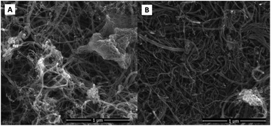
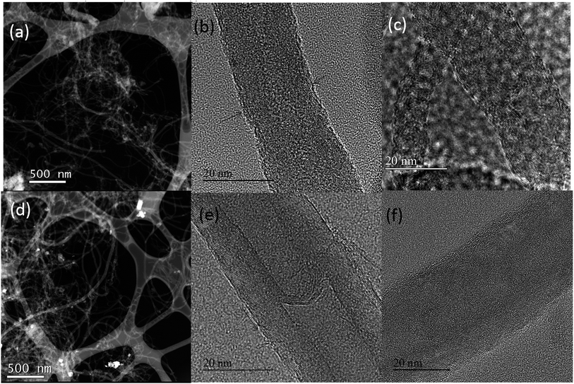
SEM measurements were used to characterise the morphological features of NCNT samples. As can be seen from Fig. 1 the surface morphology of both materials did not change much during the nitrogen doping process. The samples represent mainly MWCNT material with some inclusions which originate from CM and DCDA pyrolysis. In the case of NCNT-CM catalyst a larger amount of non-CNT material is present (Fig. 1a). These inclusions are most probably graphitic carbon nitride, which usually forms during CM or DCDA pyrolysis.63TEM images of N-doped and undoped CNT materials are shown in Fig. 2. Fig. 2a and d are overviews of the NCNT-CM and NCNT-DCDA samples, respectively. The overall morphology depicts several different nanotubes having a bamboo type structure. Moreover, the nanotubes are open ended mainly due to the acid treatment before nitrogen doping. We also observe that the inner and outer diameters of the nanotubes used in this study are variable. TEM is used to compare the surface morphology of the nanotubes with particular attention to the outer walls that are directly affected when treated with CM and DCDA. The arrows in Fig. 2b and e emphasise on the side walls of the CNTs undergoing CM and DCDA assisted N-doping, respectively. The CM assisted N-doped CNT sample shows a very thin layer of amorphous carbon on the outer surface (indicated by the arrow). The DCDA-derived N-doped CNT material does not present any real amorphous outer layer when compared to the CM-derived sample. Nevertheless, it clearly illustrates that the outermost walls of the DCDA-derived sample are discontinuous. In any case, the N-doping using CM and DCDA both show a very low amount of amorphous carbon similarly to the undoped acid-purified MWCNT samples presented in Fig. 2c and f. In Fig. 2c, two nanotubes with different inner diameters (2 nm and 5 nm) with the bamboo type structure are illustrated. Similarly in Fig. 2f a single MWCNT with an internal diameter of 10 nm is shown. In all the three acid-treated MWCNTs no explicit amorphous layer is visible irrespective of their diameters implying that the acid treatment was successful in elimination of the amorphous carbon usually present in the as-synthesised CNT materials.
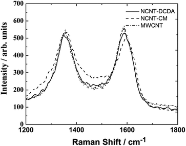
In Raman spectra of the NCNT materials (Fig. 3) the most interesting features are two peaks at approximately 1352 cm−1 (D-band) and 1580 cm−1 (G-band). Similar Raman spectrum was also observed for undoped MWCNTs. The G-band represent vibrational mode in the symmetry group of the graphite crystal planes.64 The D-band emerges from the lattice distortion in the sp2-hybridised carbon and becomes more intense with increasing number of defects.65 The measured ID/IG ratio was found to be 0.9 and 1.03 for NCNT-DCDA and NCNT-CM samples, respectively. Slightly higher ID/IG ratio for NCNT-CM sample could be due to a larger deposition of carbonaceous species onto the surface of MWCNTs, which could be seen also from the SEM images and further confirmed with TEM.
The elemental composition and chemical surrounding of nitrogen atoms in N-doped carbon nanotubes was characterised by X-ray photoelectron spectroscopy. Our previous work has shown that various oxygen-containing functionalities were present on the surface of acid-treated MWCNTs, whereas metal catalyst impurities were not detected by XPS.66 For both nitrogen-doped carbon nanotube samples the C1s peak appears at 284.8 eV, O1s at 532.1 eV and N1s at 398.2 eV (Fig. 4a for NCNT-CM and Fig. 4b for NCNT-DCDA). The high resolution spectra in the C1s region shown in Fig. 4e (NCNT-CM) and Fig. 4f (NCNT-DCDA) indicate the presence of different carbon species: C![[double bond, length as m-dash]](https://www.rsc.org/images/entities/char_e001.gif) C (284.4 eV), C–C (285.4 eV), C–O (286.6 eV), O–C
C (284.4 eV), C–C (285.4 eV), C–O (286.6 eV), O–C![[double bond, length as m-dash]](https://www.rsc.org/images/entities/char_e001.gif) O (288.2 eV), C
O (288.2 eV), C![[double bond, length as m-dash]](https://www.rsc.org/images/entities/char_e001.gif) N (285.2 eV) and C–N (286.7 eV).67–69 The exact nature and amount of carbon–oxygen functionalities is difficult to determine due to the wide and featureless shoulder on the high energy side of the C1s photoelectron line. According to literature the majority of oxygen is removed below 400 °C by pyrolysis of the oxygen-containing functional groups.70,71
N (285.2 eV) and C–N (286.7 eV).67–69 The exact nature and amount of carbon–oxygen functionalities is difficult to determine due to the wide and featureless shoulder on the high energy side of the C1s photoelectron line. According to literature the majority of oxygen is removed below 400 °C by pyrolysis of the oxygen-containing functional groups.70,71
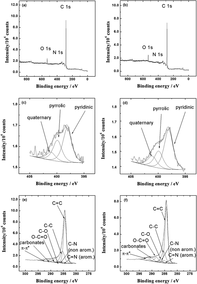 | ||
| Fig. 4 XPS survey spectra and high-resolution XPS spectra in the N1s and C1s regions (hν = 1253.6 eV, scan step 0.1 eV) for NCNT-CM (a, c and e) and NCNT-DCDA (b, d and f) samples. | ||
The removal of oxygenated species in turn might provide active sites for N doping into graphene framework.69 In the high resolution N1s spectra presented in Fig. 4c (NCNT-CM) and 4d (NCNT-DCDA), the peak can be deconvoluted into three components: pyridinic-N (398 eV), pyrrolic-N (399.9 eV) and quaternary-N (401.1 eV). Pyrrolic-N occurs in five-member ring and the nitrogen atom can contribute two p-electrons to the π-conjugated system in the graphene layers.69 The quaternary-N corresponds to nitrogen atoms that are linked with three carbon atoms in graphene basal plane and thereby replacing the carbon atoms in graphene hexagonal ring.72 Pyridinic-N occurs in six-member ring and can donate one p-electron to the aromatic π system.69 The total N content in the NCNT-DCDA catalyst was 3.7 at%, from which pyridinic-N constitutes 59 at%, quaternary-N 16 at% and pyrrolic-N 25 at%.
In NCNT-CM samples the overall nitrogen content was found to be approximately 2.3 at%, from which pyridinic-N constitutes 54 at%, quaternary-N 13 at% and pyrrolic-N 33 at%. The XPS analysis showed clearly that N-doping was successful and three different types of nitrogen species were present on the surface of NCNT materials, from which the main component is pyridinic-N.
3.2. Oxygen reduction on NCNT catalysts in alkaline media
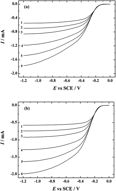
The electrocatalytic activity of both N-doped carbon nanotube catalysts was examined by the RDE method in O2-saturated 0.1 M KOH at a scan rate of 10 mV s−1. The ORR polarisation curves in the potential range of −1.2 to 0 V are presented for NCNT-CM and NCNT-DCDA catalyst materials in Fig. 5a and b, respectively. The onset potential of the ORR for NCNT-CM catalyst materials is approximately −0.08 V and for NCNT-DCDA −0.05 V, which is only slightly shifted negative as compared to that of the commercial Pt/C catalyst. Slightly lower electrocatalytic activity of NCNT-CM advert to lower nitrogen doping effect of cyanamide, which is also confirmed by the shape of the polarisation curve. Well-defined current plateaux are in evidence for the NCNT-DCDA catalyst, whereas the reduction current gradually increases for the NCNT-CM material and reaches the diffusion-limited value only at high negative potentials. The lower ORR activity of NCNT-CM could be attributed to the conductivity problems of carbon nitride material which is formed during the pyrolysis of nitrogen precursor and MWCNTs.73,74 It was also evident from SEM images that NCNT-CM catalyst had more inclusions which most probably were graphitic carbon nitride and a slightly higher amount of amorphous carbon. Difference in the ORR activity of these two NCNT catalysts can also be explained by the fact that higher N content (according to the XPS data) results in better ORR performance.It is also interesting to note that besides the difference in overall nitrogen content there are more pyridinic and quaternary and less pyrrolic nitrogen in more active NCNT-DCDA catalyst, which shows the importance in choice of nitrogen precursors for N-doping process. The reduction currents observed with NCNT-DCDA catalyst at E < −0.5 V exceed the limiting currents achieved with commercial Pt/C electrocatalyst, which exhibits great potential of this NCNT catalyst to replace Pt-based catalysts as cathode materials in alkaline fuel cells.
For the studied N-doped electrocatalysts a high oxygen reduction current was observed probably because of the unique electronic properties of these NCNTs originated from the conjugation between the lone-pair electrons of nitrogen and π electron system of carbon matrix in CNTs.75 Nitrogen will donate electrons to the conjugated π orbital of carbon, which will increase its ability to give an electron to the π* orbital in O2 molecule.76 This kind of charge delocalisation drags oxygen towards carbon and thus weakens the O–O bond of the adsorbed species until the splitting of the O2 molecule.42 It has been reported by Ruoff and co-workers that the up-mentioned process could be determined by graphitic-N and pyridinic-N which are responsible for improving the onset potential and converting the ORR mechanism from two-electron pathway to four-electron process.77 Some investigators claim that quaternary-N is responsible for the enhanced electrocatalytic activity for ORR.57,58
Despite enormous research that has been made to investigate different N-doped carbon materials, the exact electrocatalytically active nitrogen species are still under debate. Based on the XPS and RDE results obtained in this work, we could suggest that the enhanced electrocatalytic activity of the NCNT catalysts studied could be related to the higher content of pyridinic and quaternary nitrogen. In addition to electrocatalytically active nitrogen species, defects on CNTs might play a significant role in the ORR activity as well.
The occurrence of carbon vacancies on nitrogen-doped catalyst influences significantly the physical and chemical properties of CNTs. It has been proposed that the defective carbon support increases the oxygen–oxygen bond length and thereby considerably lowers the oxygen molecule's dissociation barrier.78 Density functional theory (DFT) predictions have confirmed the fact that activation of oxygen molecule and extension of the oxygen–oxygen bond distance elongation will lead to a smaller energy barrier required for dissociation.78
The number of electrons transferred per O2 molecule (n) was calculated from the Koutecky–Levich (K–L) equation:79
 | (1) |
![[thin space (1/6-em)]](https://www.rsc.org/images/entities/char_2009.gif) 485 C mol−1), ω is the rotation rate (rad s−1), DO2 is the diffusion coefficient of oxygen (1.9 × 10⁻⁵ cm2 s−1),80
485 C mol−1), ω is the rotation rate (rad s−1), DO2 is the diffusion coefficient of oxygen (1.9 × 10⁻⁵ cm2 s−1),80  is the concentration of oxygen in the bulk (1.2 × 10⁻⁶ mol cm−3)80 and ν is the kinematic viscosity of the solution (0.01 cm2 s−1).81
Fig. 6a and b present the K–L plots obtained from the RDE data on oxygen reduction for NCNT-CM (Fig. 5a) and NCNT-DCDA (Fig. 5b) at several rotation rates in 0.1 M KOH solution. The intercepts of the extrapolated K–L lines were close to zero, which indicates that the ORR process is almost entirely under the diffusion control. The insets of Fig. 6a and b show that the value of n does not depend on the potential and is 4 over the entire potential range studied. This indicates the superiority of these nitrogen-doped CNT materials and their great potential as cathode catalyst in alkaline fuel cells.
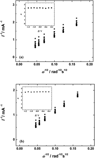 | ||
Fig. 6 Koutecky–Levich plots for oxygen reduction on (a) NCNT-CM and (b) NCNT-DCDA modified GC electrodes in 0.1 M KOH solution. E = ( ) −0.4, ( ) −0.4, ( ) −0.5, ( ) −0.5, ( ) −0.6, ( ) −0.6, ( ) −0.7, ( ) −0.7, ( ) −0.8, ( ) −0.8, ( ) −0.9, ( ) −0.9, ( ) −1.0, ( ) −1.0, ( ) −1.1 and ( ) −1.1 and ( ) −1.2 V. Inset shows the potential dependence of n. Data derived from Fig. 5. ) −1.2 V. Inset shows the potential dependence of n. Data derived from Fig. 5. | ||
Fig. 7 presents the comparative RDE results of O2 reduction for GC electrodes modified with different catalyst materials. The RDE voltammetry curves of pure GC, pristine MWCNTs and commercial Pt/C catalyst have been added for comparison purposes. It is clearly evident that the onset potential of the ORR on NCNT catalysts is considerably more positive than that of undoped MWCNT material. This shows that the catalytic activity of MWCNTs is significantly increased by nitrogen species on the surface of catalyst.
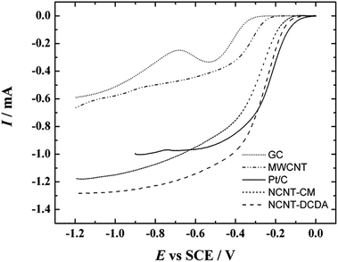 | ||
| Fig. 7 Comparison of RDE results of oxygen reduction on bare GC, MWCNT, NCNT-CM, NCNT-DCDA and Pt/C modified GC electrodes in O2-saturated 0.1 M KOH. v = 10 mV s−1, ω = 1900 rpm. | ||
The NCNT-DCDA catalyst shows a higher reduction current than any other material compared. At the foot of the polarisation curve the commercial 20 wt% Pt/C catalyst shows a higher reduction current but at more negative potentials both NCNT-CM and NCNT-DCDA modified GC electrodes become more active and the reduction current exceeds the values of the 20 wt% Pt/C catalyst material. In spite of the high reduction currents and extraordinary ORR performance of the NCNT-CM catalyst, the half-wave potential of this catalyst material is still 0.05 and 0.07 V more negative compared to the NCNT-DCDA and Pt/C catalysts, respectively.
It needs to be stressed that both CM and DCDA have been employed by other research groups as precursors for N-doping of carbon nanomaterials,14,60,61,82–84 however, to our knowledge no such comparative study on the oxygen reduction behaviour on CM- and DCDA-derived NCNTs has been reported as yet.
The linear sweep voltammetry (LSV) experiments were also carried out to study the reduction of O2 on the N-doped CNT catalysts in 0.1 M KOH. The LSV behaviour of the ORR on the NCNT-CM and NCNT-DCDA catalysts is shown in Fig. 8a and b, respectively. The LSV experiments were made using various potential scan rates (10–200 mV s−1). The peak current (Ip) is proportional to the square root of potential scan rate (v1/2) as expected for the reacting species diffusing from solution (insets of Fig. 8a and b). Comparing to the MWCNT/GC electrodes (data not shown) the LSV peak currents of NCNT-CM and NCNT-DCDA catalysts are higher and this is caused by a higher number of electrons involved for N-doped CNTs. The value of peak potential (Ep) is more positive (ca. 30 mV) for the NCNT-DCDA material, which results from higher ORR activity compared to NCNT-CM. The Ep values of both NCNT catalysts are higher than that of undoped CNTs. Similar tendency has been reported by Rybarczyk et al. recently, when studying N-doped and undoped carbon materials.85 The Ep shifts negative with increasing scan rate and this behaviour is analogous to that of the MWCNT/GC electrodes.
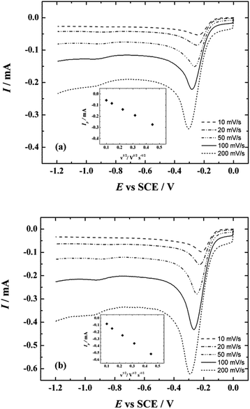 | ||
| Fig. 8 LSV curves for oxygen reduction on NCNT-CM/GC (a) and NCNT-DCDA/GC electrodes in O2-saturated 0.1 M KOH. v = 10–200 mV s−1. Inset shows the dependence of Ip on v1/2. | ||
It is clear that post-treatment of MWCNTs with either CM or DCDA results in a significant ORR activity enhancement. Whereas both N-doped catalyst materials possess excellent electrocatalytic activity towards the ORR, it is evident that the catalytic activity of CM-derived NCNTs is lower than that of DCDA-derived NCNT catalyst.
The intermediate electrocatalytic behaviour of NCNT-CM materials illustrates not only the importance of the overall nitrogen content and exact form of nitrogen achieved by N-doping, but also the role of nitrogen source in the formation of higher number of active sites.
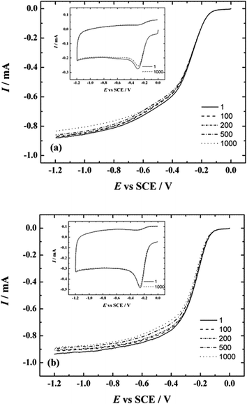
In addition to RDE and LSV measurements, the stability tests were also carried out to study the durability of these NCNT catalysts in electrochemical conditions. Both catalysts were tested under the same conditions: cycled between −1.2 and 0 V at 100 mV s−1 in O2-saturated 0.1 M KOH by applying 1000 potential cycles. The results of durability testing are shown in Fig. 9. The LSVs were recorded after every 100 cycles (insets of Fig. 9a and b) and it can be seen that the peak current values of the first and the last LSV curve have only a small difference. The value of the peak potential for NCNT-CM is approximately −0.3 V and for NCNT-DCDA ca. −0.25 V and the shift after 1000 cycles is minimal, which demonstrates that both catalysts exhibit good long-term stability.
Additionally, the RDE measurements at a scan rate of 10 mV s−1 and rotation speed of 960 rpm were performed under repetitive potential cycling. The ORR polarisation curves were recorded after every 100 cycles (Fig. 9a and b) and it can be seen that the reduction currents only slightly decrease upon potential cycling.
Furthermore, the change in the onset potential for both catalysts is minimal and it can be concluded that both catalysts maintain their stability during continuous potential cycling.
The results of the chronoamperometric tests are shown in Fig. 10. These tests confirmed the durability of the catalysts. The final current values after 10 h of stability testing were 84.85% for pure MWCNT, 85.15% for NCNT-CM and 85.65% for NCNT-DCDA catalysts. These results are similar to those of other nitrogen-doped carbon nanomaterials previously reported.3,84
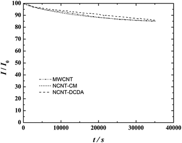 | ||
| Fig. 10 I–t curves in O2-saturated 0.1 M KOH for MWCNT, NCNT-CM and NCNT-DCDA modified GC electrodes recorded at −0.6 V, ω = 960 rpm. | ||
The electrochemical testing results show that both NCNT materials studied are promising cathode catalysts for alkaline membrane fuel cells.
4. Conclusions
High electrocatalytic ORR activity was achieved by pyrolysis of cyanamide or dicyandiamide in the presence of acid-treated multi-walled carbon nanotubes. Both of the studied catalysts showed increased selectivity towards the overall 4-electron O2 reduction pathway in alkaline media. Comparison with a commercial Pt/C catalyst showed that the nitrogen-doped carbon nanotube materials are highly active for ORR in alkaline media and therefore could be used as alternative cathode catalysts to the Pt-based materials in alkaline membrane fuel cells. The results obtained in this research indicate superior electrocatalytic properties of the developed catalyst and in the next stage of work these catalysts will be tested in the fuel cell conditions.Acknowledgements
This research was financially supported by institutional research funding (IUT20-16 and IUT2-25) of the Estonian Ministry of Education and Research and by the Estonian Research Council (Grant No. 9323) and by Archimedes Foundation (Project No. 3.2.0501.10-0015). NAMUR, the Estonian Road Map infrastructure project, is also acknowledged. We thank Valter Kiisk for assistance in collecting the Raman spectra.References
- N. Daems, X. Sheng, I. F. J. Vankelecom and P. P. Pescarmona, J. Mater. Chem. A, 2014, 2, 4085–4110 CAS.
- H. A. Gasteiger, S. S. Kocha, B. Sompalli and F. T. Wagner, Appl. Catal., B, 2005, 56, 9–35 CrossRef CAS PubMed.
- Z. Yang, H. Nie, X. A. Chen, X. Chen and S. Huang, J. Power Sources, 2013, 236, 238–249 CrossRef CAS PubMed.
- Y. Y. Shao, J. H. Sui, G. P. Yin and Y. Z. Gao, Appl. Catal., B, 2008, 79, 89–99 CrossRef CAS PubMed.
- C. W. B. Bezerra, L. Zhang, K. Lee, H. Liu, A. L. B. Marques, E. P. Marques, H. Wang and J. Zhang, Electrochim. Acta, 2008, 53, 4937–4951 CrossRef CAS PubMed.
- X. Z. Yuan and H. Wang, in PEM Fuel Cell Electrocatalysts and Catalyst Layers: Fundamentals and Applications, ed. J. Zhang, Springer, London, 2008, pp. 1–87 Search PubMed.
- D. Higgins, Z. Chen and Z. Chen, Electrochim. Acta, 2011, 56, 1570–1575 CrossRef CAS PubMed.
- K. N. Wood, R. O'Hayre and S. Pylypenko, Energy Environ. Sci., 2014, 7, 1212–1249 CAS.
- L. Zhang and Z. Xia, J. Phys. Chem. C, 2011, 115, 11170–11176 CAS.
- D.-W. Wang and D. Su, Energy Environ. Sci., 2014, 7, 576–591 CAS.
- Y. Shao, G. Yin, J. Zhang and Y. Gao, Electrochim. Acta, 2006, 51, 5853–5857 CrossRef CAS PubMed.
- Y. Shao, G. Yin and Y. Gao, J. Power Sources, 2007, 171, 558–566 CrossRef CAS PubMed.
- P. Trogadas, T. F. Fuller and P. Strasser, Carbon, 2014, 75, 5–42 CrossRef CAS PubMed.
- D. C. Higgins, J. Wu, W. Li and Z. Chen, Electrochim. Acta, 2012, 59, 8–13 CrossRef CAS PubMed.
- S. Maldonado, S. Morin and K. J. Stevenson, Carbon, 2006, 44, 1429–1437 CrossRef CAS PubMed.
- E. J. Biddinger, D. V. Deak and U. S. Ozkan, Top. Catal., 2009, 52, 1566–1574 CrossRef CAS.
- Y. Wang, X. Cui, Y. Li, L. Chen, H. Chen, L. Zhang and J. Shi, Carbon, 2014, 68, 232–239 CrossRef CAS PubMed.
- S. Maass, F. Finsterwalder, G. Frank, R. Hartmann and C. Merten, J. Power Sources, 2008, 176, 444–451 CrossRef CAS PubMed.
- G. Che, B. B. Lakshmi, E. R. Fisher and C. R. Martin, Nature, 1998, 393, 346–349 CrossRef CAS.
- S. Maldonado and K. J. Stevenson, J. Phys. Chem. B, 2005, 109, 4707–4716 CrossRef CAS PubMed.
- J. Wang, G. Yin, Y. Shao, Z. Wang and Y. Gao, J. Phys. Chem. C, 2008, 112, 5784–5789 CAS.
- B. Wang, J. Power Sources, 2005, 152, 1–15 CrossRef CAS PubMed.
- P. Ayala, R. Arenal, M. Rümmeli, A. Rubio and T. Pichler, Carbon, 2010, 48, 575–586 CrossRef CAS PubMed.
- Z. W. Chen, D. Higgins, A. P. Yu, L. Zhang and J. J. Zhang, Energy Environ. Sci., 2011, 4, 3167–3192 CAS.
- R. Liu, D. Wu, X. Feng and K. Müllen, Angew. Chem., Int. Ed., 2010, 49, 2565–2569 CrossRef CAS PubMed.
- Q. Guo, D. Zhao, S. Liu, S. Chen, M. Hanif and H. Hou, Electrochim. Acta, 2014, 138, 318–324 CrossRef CAS PubMed.
- Y. Ma, L. Sun, W. Huang, L. Zhang, J. Zhao, Q. Fan and W. Huang, J. Phys. Chem. C, 2011, 115, 24592–24597 CAS.
- Z. Chen, D. Higgins and Z. Chen, Carbon, 2010, 48, 3057–3065 CrossRef CAS PubMed.
- J. D. Wiggins-Camacho and K. J. Stevenson, J. Phys. Chem. C, 2009, 113, 19082–19090 CAS.
- D. Geng, H. Liu, Y. Chen, R. Li, X. Sun, S. Ye and S. Knights, J. Power Sources, 2011, 196, 1795–1801 CrossRef CAS PubMed.
- H. Li, H. Liu, Z. Jong, W. Qu, D. Geng, X. Sun and H. Wang, Int. J. Hydrogen Energy, 2011, 36, 2258–2265 CrossRef CAS PubMed.
- H. Liu, Y. Zhang, R. Li, X. Sun, S. Désilets, H. Abou-Rachid, M. Jaidann and L.-S. Lussier, Carbon, 2010, 48, 1498–1507 CrossRef CAS PubMed.
- C. Jin, T. C. Nagaiah, W. Xia, B. Spliethoff, S. Wang, M. Bron, W. Schuhmann and M. Muhler, Nanoscale, 2010, 2, 981–987 RSC.
- M. Borghei, P. Kanninen, M. Lundahl, T. Susi, J. Sainio, I. Anoshkin, A. Nasibulin, T. Kallio, K. Tammeveski, E. Kauppinen and V. Ruiz, Appl. Catal., B, 2014, 158–159, 233–241 CrossRef CAS PubMed.
- E. J. Biddinger and U. S. Ozkan, J. Phys. Chem. C, 2010, 114, 15306–15314 CAS.
- W. Y. Wong, W. R. W. Daud, A. B. Mohamad, A. A. H. Kadhum, K. S. Loh, E. H. Majlan and K. L. Lim, Electrochim. Acta, 2014, 129, 47–54 CrossRef CAS PubMed.
- A. Dorjgotov, J. Ok, Y. Jeon, S. H. Yoon and Y. G. Shul, J. Appl. Electrochem., 2013, 43, 387–397 CrossRef CAS PubMed.
- H. Li, X. Cheng, F.-B. Weng, A. Su and Y.-C. Chiang, J. Electrochem. Soc., 2014, 161, F1140–F1145 CrossRef PubMed.
- Z. Mo, S. Liao, Y. Zheng and Z. Fu, Carbon, 2012, 50, 2620–2627 CrossRef CAS PubMed.
- M. Vikkisk, I. Kruusenberg, U. Joost, E. Shulga and K. Tammeveski, Electrochim. Acta, 2013, 87, 709–716 CrossRef CAS PubMed.
- S. Ratso, I. Kruusenberg, M. Vikkisk, U. Joost, E. Shulga, I. Kink, T. Kallio and K. Tammeveski, Carbon, 2014, 73, 361–370 CrossRef CAS PubMed.
- X. Tuaev, J. P. Paraknowitsch, R. Illgen, A. Thomas and P. Strasser, Phys. Chem. Chem. Phys., 2012, 14, 6444–6447 RSC.
- Z. Wang, R. Jia, J. Zheng, J. Zhao, L. Li, J. Song and Z. Zhu, ACS Nano, 2011, 5, 1677–1684 CrossRef CAS PubMed.
- W. Y. Wong, W. R. W. Daud, A. B. Mohamad, A. A. H. Kadhum, K. S. Loh and E. H. Majlan, Int. J. Hydrogen Energy, 2013, 38, 9370–9386 CrossRef CAS PubMed.
- T. Sharifi, G. Hu, X. Jia and T. Wågberg, ACS Nano, 2012, 6, 8904–8912 CrossRef CAS PubMed.
- C. Xiong, Z. Wei, B. Hu, S. Chen, L. Li, L. Guo, W. Ding, X. Liu, W. Ji and X. Wang, J. Power Sources, 2012, 215, 216–220 CrossRef CAS PubMed.
- J. Liu, R. Czerw and D. L. Carroll, J. Mater. Res., 2005, 20, 534–538 Search PubMed.
- G. Liu, X. Li, P. Ganesan and B. N. Popov, Electrochim. Acta, 2010, 55, 2853–2858 CrossRef CAS PubMed.
- J. Yin, Y. Qiu and J. Yu, J. Electroanal. Chem., 2013, 702, 56–59 CrossRef CAS PubMed.
- R. Droppa, P. Hammer, A. C. M. Carvalho, M. C. dos Santos and F. Alvarez, J. Non-Cryst. Solids, 2002, 299–302, 874–879 CrossRef CAS.
- W. Y. Wong, W. R. W. Daud, A. B. Mohamad, A. A. H. Kadhum, K. S. Loh and E. H. Majlan, Int. J. Hydrogen Energy, 2013, 38, 9421–9430 CrossRef CAS PubMed.
- N. Alexeyeva, E. Shulga, V. Kisand, I. Kink and K. Tammeveski, J. Electroanal. Chem., 2010, 648, 169–175 CrossRef CAS PubMed.
- A. Zhao, J. Masa, W. Schuhmann and W. Xia, J. Phys. Chem. C, 2013, 117, 24283–24291 CAS.
- Y. J. Sa, C. Park, H. Y. Jong, S.-H. Park, Z. Lee, K. T. Kim, G.-G. Park and S. H. Joo, Angew. Chem., Int. Ed., 2014, 53, 4102–4106 CrossRef CAS PubMed.
- J. D. Wiggins-Camacho and K. J. Stevenson, J. Phys. Chem. C, 2011, 115, 20002–20010 CAS.
- K. Gong, F. Du, Z. Xia, M. Durstock and L. Dai, Science, 2009, 323, 760–764 CrossRef CAS PubMed.
- Z. Lin, G. Waller, Y. Liu, M. Liu and C.-P. Wong, Adv. Energy Mater., 2012, 2, 884–888 CrossRef CAS PubMed.
- Y. Sun, C. Li and G. Shi, J. Mater. Chem., 2012, 22, 12810–12816 RSC.
- L. Wang, L. Zhang and J. Zhang, Electrochem. Commun., 2011, 13, 447–449 CrossRef CAS PubMed.
- M. Vikkisk, I. Kruusenberg, U. Joost, E. Shulga, I. Kink and K. Tammeveski, Appl. Catal., B, 2014, 147, 369–376 CrossRef CAS PubMed.
- J. Tian, L. Birry, F. Jaouen and J. P. Dodelet, Electrochim. Acta, 2011, 56, 3276–3285 CrossRef CAS PubMed.
- I. Kruusenberg, M. Marandi, V. Sammelselg and K. Tammeveski, Electrochem. Solid-State Lett., 2009, 12, F31–F34 CrossRef CAS PubMed.
- A. Thomas, A. Fischer, F. Goettmann, M. Antonietti, J.-O. Müller, R. Schlögl and J. M. Carlsson, J. Mater. Chem., 2008, 18, 4893–4908 RSC.
- J. H. Lehman, M. Terrones, E. Mansfield, K. E. Hurst and V. Meunier, Carbon, 2011, 49, 2581–2602 CrossRef CAS PubMed.
- M. S. Dresselhaus, A. Jorio, M. Hofmann, G. Dresselhaus and R. Saito, Nano Lett., 2010, 10, 751–758 CrossRef CAS PubMed.
- I. Kruusenberg, N. Alexeyeva, K. Tammeveski, J. Kozlova, L. Matisen, V. Sammelselg, J. Solla-Gullón and J. M. Feliu, Carbon, 2011, 49, 4031–4039 CrossRef CAS PubMed.
- V. Datsyuk, M. Kalyva, K. Papagelis, J. Parthenios, D. Tasis, A. Siokou, I. Kallitsis and C. Galiotis, Carbon, 2008, 46, 833–840 CrossRef CAS PubMed.
- Z. Luo, S. Lim, Z. Tian, J. Shang, L. Lai, B. MacDonald, C. Fu, Z. Shen, T. Yu and J. Lin, J. Mater. Chem., 2011, 21, 8038–8044 RSC.
- Z. H. Sheng, L. Shao, J. J. Chen, W. J. Bao, F. B Wang and X. H. Xia, ACS Nano, 2011, 5, 4350–4358 CrossRef CAS PubMed.
- H. C. Schniepp, J. L. Li, M. J. McAllister, H. Sai, M. Herrera-Alonso, D. H. Adamson, R. K. Prud'homme, R. Car, D. A. Saville and I. A. Aksay, J. Phys. Chem. B, 2006, 110, 8535–8539 CrossRef CAS PubMed.
- S. Chandra, S. Sahu and P. Pramanik, Mater. Sci. Eng., B, 2010, 167, 133–136 CrossRef CAS PubMed.
- H. Wang, T. Maiyalagan and X. Wang, ACS Catal., 2012, 2, 781–794 CrossRef CAS.
- L. Feng, L. Yang, Z. Huang, J. Luo, M. Li, D. Wang and Y. Chen, Sci. Rep., 2013, 3, 1–8 Search PubMed.
- Y. Gong, J. Wang, Z. Wei, P. Zhang, H. Li and Y. Wang, ChemSusChem, 2014, 7, 2303–2309 CrossRef CAS PubMed.
- K. Kurak and A. B. Anderson, J. Phys. Chem. C, 2009, 113, 6730–6734 CAS.
- Q. Liu, H. Zhang, H. Zhong, S. Zhang and S. Chen, Electrochim. Acta, 2012, 81, 313–320 CrossRef CAS PubMed.
- L. F. Lai, J. R. Potts, D. Zhan, L. Wang, C. K. Poh, C. H. Tang, H. Gong, Z. Shen, J. Lin and R. S. Ruoff, Energy Environ. Sci., 2012, 5, 7936–7942 CAS.
- D. H. Lim and J. Wilcox, J. Phys. Chem. C, 2011, 115, 22742–22747 CAS.
- A. J. Bard and L. R. Faulkner, Electrochemical Methods, Wiley, New York, 2nd edn, 2001 Search PubMed.
- R. E. Davis, G. L. Horvath and C. W. Tobias, Electrochim. Acta, 1967, 12, 287–297 CrossRef CAS.
- D. R. Lide, CRC Handbook of Chemistry and Physics, CRC Press, Boca Raton, 82nd edn, 2001 Search PubMed.
- H. T. Chung, J. H. Won and P. Zelenay, Nat. Commun., 2013, 4, 1922 CrossRef PubMed.
- H. T. Chung, C. M. Johnston and P. Zelenay, ECS Trans., 2009, 25, 485–492 CAS.
- C. H. Choi, M. W. Chung, S. H. Park and S. I. Woo, RSC Adv., 2013, 3, 4246–4253 RSC.
- M. K. Rybarczyk, M. Lieder and M. Jablonska, RSC Adv., 2015, 5, 44969–44977 RSC.
| This journal is © The Royal Society of Chemistry 2015 |

