Electrolytic recovery of bismuth and copper as a powder from acidic sulfate effluents using an emew® cell

Wei Jina, Paul I. Laforesta, Alex Luyimaa, Weldon Readb, Luis Navarrob and Michael S. Moats*a
aMaterials Research Center, Missouri University of Science and Technology, Rolla, Missouri 65409, USA. E-mail: moatsm@mst.edu; Fax: +1 573 341 6934; Tel: +1 573 341 6974
bASARCO, 7001 State Highway 136, Amarillo, Texas 79106, USA

Received 5th May 2015 , Accepted 30th May 2015

First published on 1st June 2015


Abstract

Effective removal of bismuth is a primary concern during copper electrorefining. A novel electrowinning process using an emew® cell was developed to recover bismuth and copper from a copper electrorefining waste stream. Significant removal and co-deposition of copper and bismuth were achieved from a highly acidic sulfate industrial effluent using a current density of 350 A m−2, but the current efficiency was low (27%). Operating at a lower current density (75 A m−2) facilitated the preferred removal of Cu, while increasing current efficiency to 67.4% due to the decrease of aside-reaction. Consequently, a two-stage process was employed to remove most of the copper at low current and then extract bismuth at high current. 93.4% of the bismuth and 97.8% of the copper were recovered with a satisfactory current efficiency, and a high purity (∼98%) Bi powder was obtained in the second step. This novel emew® cell approach may serve as a promising alternative for recovering copper and bismuth, and the proposed two step strategy may offer insight for the selective recovery of metals in a multi-component system.

1. Introduction

In the primary production of copper using pyrometallurgical methods, electrorefining is required to produce high purity metal.1 During copper electrorefining, many impurities from the original copper concentrate, such as group 15 elements (bismuth, antimony and arsenic), are dissolved along with copper into the sulfuric acid electrolyte.2 The accumulation of these impurities can result in cathode contamination, floating slime formation and reduction of current efficiency.3 Therefore, the removal of impurities from the electrolyte is a key concern for copper electrorefineries.4

Conventionally, the purification of copper electrolyte is achieved by electrowinning in liberator cells where impurities are removed from the electrolyte by their co-deposition with copper. However, this technique has some drawbacks such as low current efficiency and loss of possible by-products, particularly bismuth.5,6 Although the standard reduction potentials of Bi3+ and Cu2+ are very close as shown in eqn (1) and (2),7 few authors have reported the co-deposition of Cu and Bi by electrowinning in acidic media.8 Hoffmann indicated that bismuth does not electrolytically co-deposit with copper under normal electrowinning conditions9 and the bismuth removal in the conventional copper electrolyte purification is limited. This is due to the fact that the electrodeposition reaction is largely determined by the diffusion of the reactant ion. Bismuth deposition is limited when copper concentration is high (>15 g L−1) and bismuth concentration is low (<0.3 g L−1). The diffusion coefficient of copper ion is also nearly 3.5 times more than the bismuth ion.10,11

 
Bi3+ + 3e ⇆ Bi(s) + 0.308 V (vs. RHE) (1)
 
Cu2+ + 2e ⇆ Cu(s) + 0.340 V (vs. RHE) (2)

Furthermore, bismuth is widely employed in semiconductor, thermoelectric and electrochromic devices.10 It is obtained as a by-product from the production of copper, silver, lead and tin ores.12,13 Therefore, bismuth recovery from copper electrorefining electrolytes could produce a valuable by-product from an otherwise problematic element for copper.

Recently, a new electrowinning technology, the emew® cell, has been developed based on re-design of the electrowinning chamber.14,15 The cell is constructed from a pair of concentric tubular electrodes with a closed chamber, and the target solution can be pumped at high flow rates between the electrodes to obtain improved mass transport.15 Consequently, a much higher current efficiency and larger operating window can be achieved in this new cell.15,16 The electrowinning of copper, nickel, cobalt, zinc, gold and silver have been reported using this type of cell.14,16 Moreover, it has been employed to recover metals from industrial waste solutions.15 Obviously, extending this new technology to the electrowinning of bismuth could overcome the diffusion limitation of Bi/Cu co-deposition and result in the substantial improvement in the treatment of copper electrorefining effluents.

In this regard, the aim of this study is to develop a novel electrowinning process using an emew® cell to recover bismuth from a copper electrorefining waste stream. The co-deposition behavior of Bi and Cu in the electrowinning process was also investigated to understand the mechanism of the current efficiency results obtained. This approach may serve as a promising alternative for overcoming the disadvantages of existing bismuth production techniques and/or copper electrorefining electrolyte treatments.

2. Materials and methods

2.1 Materials

The chemical reagents used in the preparation of synthetic solutions used in this study were all of analytical grade purity and used as received, including sulfuric acid (GFS Chemicals, 95.0–98.0 wt%) and bismuth(III) nitrate pentahydrate (Sigma-Aldrich, ≥98.0 wt%). A synthetic solution was prepared by dissolving the corresponding sulfuric acid and bismuth salt into ultrapure water (18 MΩ cm) obtained from a water purification system.

An industrial solution was provided by ASARCO from their copper refinery electrolyte purification system. Its composition is listed in Table 1. Acid concentration was analyzed by titration while the other elements were determined by inductively coupled atomic plasma emission spectrometry (ICP-AES).

Table 1 Industrial effluent chemical composition
Cu (g L−1) H2SO4 (g L−1) Cl (g L−1) Sb (g L−1) As (g L−1) Pb (g L−1) Bi (g L−1)
0.8 604 0.026 0.2 <0.1 <0.1 3.44


2.2 Electrochemical studies

To understand the basic electrochemistry of bismuth electrodeposition, cyclic voltammetry (CV) was performed at ambient temperature using a Gamry (reference 3000) electrochemical workstation. A three electrode cell with a 316L stainless steel working electrode (active area of 1.0 cm2), an IrO2–Ta2O5 coated titanium counter electrode and a double junction Ag/AgCl (0.22 V vs. SHE) reference electrode was employed. Prior to each experiment, the stainless steel plate was prepared by successively polishing using 180, 400 and 600 grit silicon carbide sandpaper in order to obtain a smooth, even surface for deposition. Following polishing, the electrode was washed and sonicated in water. The electrochemical measurements were then performed in N2-purged solutions by potential cycling from −0.18 V to 1.0 V vs. SHE at various scan rates. All potentials are reported versus SHE.

Linear sweep voltammetry (LSV) and chronopotentiometry (CP) were used to understand hydrogen evolution from the industrial effluent on stainless steel. LSV and CP were performed with the same electrochemical cell and electrodes as described in the CV procedure. The potential range for LSV was 0.5 V to −0.4 V with a scan rate of 10 mV s−1. Chronopotentiometric experiments were conducted at 75, 175 and 350 A m−2 to correspond to the current densities used in emew® cell experiments. Both LSV and CP were conducted with electrolyte stirring to approximate the hydrodynamic conditions of the cell.

2.3 emew® cell test

A laboratory scale emew® system was provided by Electrometals, USA. A schematic drawing and an image of the system are shown in Fig. 1. The cell is tubular in nature with an IrO2–Ta2O5 coated titanium anode in the center and a stainless steel foil cathode on the outside of the tube. The cell has a cathode area of 0.04 m2. Current was applied at 3, 7, or 14 amps or at cathodic current densities of 75, 175, or 350 A m−2, respectively. Current was applied for 20, 30, 45 or 90 minutes depending on the purpose of the test.
image file: c5ra08318d-f1.tif
Fig. 1 Schematic diagram and photograph of the laboratory emew® cell setup.

Experiments with the emew® system were conducted at ambient temperature and pressure. 3 liters of solution were used in each test. The flow rate used was 5 L min−1, unless otherwise specified. Most tests were conducted with the industrial solution. One test was conducted using a synthetic solution of 3.44 g L−1 Bi(III) and 604 g L−1 H2SO4.

2.4 Powder characterization

The surface morphology and approximate composition of prepared powder from the electrowinning tests were characterized using a Helios Nanolab 600 scanning electron microscopy (SEM) with energy dispersive X-ray spectroscopy (EDS), while its crystalline structure was measured using a PANanalytical X'Pert X-ray diffractometry (XRD) with Cu Kα radiation. The Cu/Bi ratio of the powder sample was determined by EDS, while its relative speciation was obtained by XRD after calibration using samples of known mixtures. The mean particle sizes and size distribution were determined using a Microtrac S3500 particle size analyzer.

3. Results and discussion

3.1 Electrochemical reduction of Bi(III) in concentrated sulfuric acid solution

Cyclic voltammetric (CV) measurements were performed using the synthetic Bi(III)–sulfuric acid solution to determine the electrochemical reduction performance of Bi(III) at the stainless steel electrode. The H2SO4 concentration of 604 g L−1 and Bi(III) concentration of 3.44 g L−1 were selected to be the same as the industrial solution. As shown in Fig. 2, a well-defined reduction peak emerged at 0.05 V with a peak current density of 3.12 mA cm−2 in the presence of Bi(III), while no reduction peak was observed in the same potential region when Bi(III) was not in the sulfuric acid solution, indicating this peak is related to Bi(III) reduction. There is the corresponding oxidation peak at 0.17 V with a maximum current density of 1.35 mA cm−2 in the reverse scan of the CV curve in the presence of Bi(III), suggesting a quasi-reversible reaction. It should be noted that a crossover occurs at 0.08 V. This crossover indicates that bismuth deposits easier upon itself than on stainless steel. The experiment indicates, an overpotential of ∼68 mV is required to promote Bi(III) nuclei formation on 316L stainless steel. These results indicate that Bi(III) electrodeposition on the stainless steel electrode in concentrated sulfuric acid solution occurs if an adequate potential is applied.
image file: c5ra08318d-f2.tif
Fig. 2 Cyclic voltammograms using a stainless steel working electrode in the absence and presence of 3.44 g L−1 Bi(III) in a solution of 604 g L−1 H2SO4, scan rate = 10 mV s−1, ambient temperature.

In order to further characterize the electrochemical reduction of Bi(III), potential scans were performed at different rates (from 10 to 50 mV s−1). As can be seen in Fig. 3a, a negative shift in the cathodic peak potential with increasing sweep rate is observed, which agrees with the theory of a quasi-reversible reaction.17 There is also a linear relationship between the Bi(III) reduction peak current and the square root of scan rate (v1/2) as seen in Fig. 3b, indicating the reaction is diffusion-controlled.18,19 In general, the peak current of a diffusion-controlled quasi-reversible electrochemical reaction at 298 K for an insoluble product can be described by the following equation:20

 
Ip = 367n3/2AD1/2Cv1/2 (3)
where Ip (A) is the peak current, n is the number of electrons (n = 3 for Bi(III) reduction), A (cm2) is the surface area of the working electrode, D (cm2 s−1) is the diffusion coefficient of Bi(III), C (mol L−1) is the bulk Bi(III) concentration, and v (V s−1) is the scan rate. Using this equation and the slope from the least-squares fit linear correlation curve shown in Fig. 3b, the diffusion coefficient of Bi(III) was calculated to be 0.89 × 10⁻⁶ cm2 s−1. This value appears reasonable as compared to the reported value of 1.72 × 10⁻⁶ cm2 s−1 in 1 mol L−1 HNO3 solution.10 It is believed that the Bi(III) diffusion coefficient in the strong sulfuric acid solution (∼6.45 M) used in his study is lower due to higher solution viscosity. Given the low concentration of Bi(III) in solution and its small diffusion coefficient, the emew® cell is expected to overcome the diffusion issues better than a parallel plate cell because of its improved design.


image file: c5ra08318d-f3.tif
Fig. 3 Bi(III) reduction behavior as a function of scan rate on stainless steel: (a) cyclic voltammograms with increasing scan rate (10–50 mV s−1); (b) variation of the reduction peak current as a function of the square root of the scan rate in synthetic solution of 3.44 g L−1 Bi(III) and 604 g L−1 H2SO4.

3.2 Treatment of synthetic Bi(III) solution

The electrowinning performance of a synthetic Bi(III)-containing solution was evaluated using an emew® cell, and the treatment was conducted with a current of 14 A (350 A m−2) and a solution flow rate of 5 L min−1. As shown in Table 2, 9.3 g of powder product were obtained after a 20 min treatment. The powder was determined to be crystalline Bi using XRD (Fig. 4), which confirms the feasibility of Bi powder electrowinning from a concentrated acidic sulfate solution. Nearly 94.9% of the Bi content was extracted from the three liters of solution in this 20 min treatment and most of the as-prepared Bi powder was removed by washing with water. This indicates that the Bi powder could be flushed from the cell with water, which overcomes a disadvantage of powder harvesting from a conventional electrowinning cell.
Table 2 Performance of emew cell treatment with synthetic and industrial effluents
Test # Electrolyte Current (A m−2) Flow rate (L min−1) Run time (min) Product weight (g) Product composition Current efficiency Cu removal Bi removal
a The data were calculated for the whole process.
1 Synthetic 350 5 20 9.3 Bi 100 wt% 76.7% 94.9%
2 Industrial 350 5 30 4.2 Cu2O 21 wt%, Cu 14 wt%, Bi 65 wt% 26.7% 57.2% 26.5%
3 Industrial 350 8 30 4.8 Cu2O 19 wt%, Cu 17 wt%, Bi 64 wt% 31.5% 67.8% 29.8%
4 Industrial 175 5 30 2.5 Cu2O 15%, Cu 53 wt%, Bi 32 wt% 44.5% 69.1% 7.8%
5 Industrial 75 5 90 5.3 Cu 42 wt%, Bi 58 wt% 67.4% 92.7% 29.8%
6 Industrial 350 5 90 12.1 Cu2O 13 wt%, Cu 8 wt%, Bi 79 wt% 27.4% 98.6% 92.6%
7 Industrial 75 5 90 5.3 Cu 42 wt%, Bi 58 wt% 67.4% 92.7% 29.8%
350 5 20 6.7 Cu2O 1 wt%, Cu 1 wt%, Bi 98 wt% 55.8% 97.8%a 93.4%a
61.6%a


image file: c5ra08318d-f4.tif
Fig. 4 XRD spectrum of the as-prepared cathodic deposit from emew cell using a synthetic solution (3.44 g L−1 Bi3+, 604 g L−1 H2SO4) after 350 A m−2 and 20 min: flow rate = 5 L min−1.

The current efficiency was calculated to be 76.7%, which is much higher than the previous 30.6% reported under similar conditions in a conventional electrowinning cell.8 This significant improvement is believed to be due to the excellent mass transport of the cell. It should also be noted that the working cathode employed in our treatment was an inexpensive stainless steel sheet (foil), while the reported treatment in the conventional cell was a more expensive Nb electrode.

3.3 Co-deposition of Bi and Cu

As discussed earlier, the removal of bismuth from copper electrorefining electrolyte is a problem in copper production.21 However, industrial solutions typically contain multiple metals with various counter anions. The ASARCO industrial solution contains primarily Bi (3.44 g L−1) and Cu (0.8 g L−1) in a high concentration of sulfuric acid (604 g L−1), while the Cl, Sb, Pb and As concentrations are relatively low.

In order to determine the electrochemical behavior of Bi(III) in the presence of other impurities, cyclic voltammetry using the industrial solution was performed and the results are presented in Fig. 5. As compared to the synthetic solution, the reduction peak shifts slightly positive to 0.06 V and the current density increases slightly to 3.63 mA cm−2. The standard reduction potentials of Bi(III) and Cu(II) are very close with the potential of Cu(II) reduction occurring at slightly more positive potentials. Therefore, the shift of peak potential and current in the industrial solution is probably due to the combination of Bi and Cu reduction. The cyclic voltammogram from the industrial solution also reveals the oxidation peak of the metal deposited during the reduction sweep shifts positively and the peak current is significantly higher as compared to the data from the synthetic solution which does not contain copper. Thus, the higher oxidation current is attributed to the influence of Cu-related dissolution.


image file: c5ra08318d-f5.tif
Fig. 5 Comparison of the cyclic voltammograms between the synthetic and the industrial effluents at stainless steel electrode: scan rate = 10 mV s−1.

Electrolytic metal recovery from the industrial solution using the laboratory cell was first examined using 350 A m−2 and a solution flow rate of 5 L min−1 for 30 minutes. At the end of the test, a powder was removed by washing the stainless steel foil with water. The powder was filtered, dried in air and characterized. SEM and EDS analyses indicate the powder consisted of Bi and Cu with some oxides present (see Fig. 6). XRD confirmed the presence of Bi, Cu and Cu2O as shown in Fig. 7a. The composition of the powder was estimated by combining the XRD and EDS results as 21 wt% Cu2O, 14 wt% Cu and 65 wt% Bi. The formation of Cu2O is believed to occur by the partial reduction of Cu2+ to Cu+ followed by the precipitation of Cu+ as Cu2O due to the very low solubility of monovalent copper in solution. It is common to see copper “burn” (e.g. form Cu2O) during high current density plating in acidic sulfate baths when the agitation or mass transport is not great enough.22 These results indicate the co-deposition of Bi, Cu and Cu2O from the industrial solution under these conditions. Based on the estimated composition of the deposit 57.2% of the copper and 26.5% of the bismuth was removed from the solution by the 30 minute treatment. The current efficiency was calculated to be 26.7%. Clearly, the co-deposition performance of Cu and Bi was not complete or particularly energy efficient.


image file: c5ra08318d-f6.tif
Fig. 6 (a) SEM image and (b) EDS spectrum of the as-prepared cathodic deposit in the industrial effluents after 350 A m−2 and 30 min emew® treatment: flow rate = 5 L min−1.

image file: c5ra08318d-f7.tif
Fig. 7 XRD spectra of the as-prepared cathodic deposit in the industrial effluents after (a) 350 A m−2 and 30 min; (b) 75 A m−2 and 90 min emew treatments: flow rate = 5 L min−1.

Given the formation of cuprous oxide, a higher flow rate of 8 L min−1 was employed to the cell in an attempt to minimize the “burning” of the deposit while maintaining the current density at 350 A m−2 for 30 minutes. A slight improvement (higher current efficiency or removal rate) was obtained as shown in Table 2. Cu2O however was still formed indicating that even at a high flow rate to the laboratory scale cell, the selected current density (350 A m−2) was likely too high for copper plating. Consequently, the flow rate was returned to 5 L min−1 and maintained at that level in subsequent measurements.

A treatment using a lower current density (175 A m−2) for 30 minutes was then examined. The product weight and composition was significantly different from those produced at 350 A m−2. The weight of the powder product was lower at lower current as expected (2.5 g vs. 4.8 g). More interestingly, there was a substantial decrease in Bi reduction and the formation of Cu2O. This suggests the composition of the deposit is current (e.g. potential) dependent. The lower current promoted the deposition of copper while inhibiting bismuth and Cu2O formation. This likely occurred by the lower current density promoting a more positive potential at the cathode surface which favored copper electrodeposition at the expense of the other two reactions. At the lower current density, the current efficiency was also improved (44.5% vs. 26.7% at 350 A m−2). The powder composition and energy efficiency can be modified by changing the current input to the emew® cell during the treatment of the industrial solution.

An even lower current density (75 A m−2) was applied to the cell with a longer treatment time of 90 min to examine if better performance could be achieved. As illustrated in the Table 2, nearly 92.7% of copper was removed as Cu metal from the industrial solution and a much higher current efficiency (67.4%) was achieved. Interestingly only 29.8% of the Bi was recovered in this treatment. No Cu2O was detected in the XRD analysis of the powder. Therefore, it appears a suitably low level of current applied to the cell may facilitate Cu formation over Cu2O and Bi metal.

The preferred electrodeposition of copper over bismuth at the lower current density is related to its higher standard reduction potential. The CV shown in Fig. 5 reveals that reversible potential of the industrial effluent is more positive as compared to the synthetic bismuth only solution. This indicates that even with the low concentration of copper in the industrial effluent, it is potentially more favored than bismuth reduction. Thus, at lower current densities copper deposits more quickly than bismuth. Optimization of the plating current and time in the first stage could further improve the separation of copper from bismuth.

A loss in current efficiency during electrochemical deposition of powders can be caused be re-solution of the powder when the particles lose electrical contact with the cathode substrate. The possible re-solution of particles was examined by measuring the particle size distributions for selected emew® produced powders from the treatment of the industrial effluent. The particle size distributions are shown in Fig. 8. The mean particles size for the current densities of 350 A m−2, 175 A m−2 and 75 A m−2 were 130 μm, 90 μm and 35 μm, respectively. Smaller particle sizes typically lead to an increase dissolution rate due to higher specific surface area.22 Since current efficiency decreases with increasing current density and larger mean particle size, it suggests the main source of current inefficiency is not re-solution of particles.


image file: c5ra08318d-f8.tif
Fig. 8 Particle size distributions for powers produced in the emew® cell when different current densities were applied.

On the other hand, it is well known that lowering the operating current density can result in the enhancement of current efficiency by better matching the applied current to the mass transport of the desired ion to be reduced.23 This increases current efficiency by limiting the amount of current lost to a side reaction that occurs at a more cathodic potential. The possible influence of a side-reaction was investigated by measuring chronopotentiometric curves using a stainless steel working electrode in a three electrode cell with significant agitation (to simulate the high surface mass transport conditions in an emew® cell) of the industrial effluent at the current densities employed in the laboratory electrowinning experiments.

The chronopotentiometric results are presented in Fig. 9. The obtained potentials at 350 A m−2, 175 A m−2, and 75 A m−2 are −0.46 V, −0.34 V, and −0.19 V, respectively. These potentials were compared to the potential at which hydrogen evolution occurs on a stainless steel cathode after some plating of copper and bismuth has occurred. The hydrogen evolution onset potential was determined using linear sweep voltammetry and is observed after some reduction of copper and bismuth on the stainless surface to be −0.24 V in the industrial effluent (see inset curve in Fig. 9). From these data, it appears that as current density was increased in the emew® cell, a more negative cathode potential was produced which allowed hydrogen evolution to occur leading to the decrease in current efficiency observed.


image file: c5ra08318d-f9.tif
Fig. 9 Chronopotentiometric curves using a stainless steel working electrode in the industrial effluents produced at different current densities with stirring; inset: linear sweep voltammogram produced using the industrial effluent with a stainless steel working electrode, scan rate = 10 mV s−1.

3.4 Two-stage emew® cell treatment

The preceding experiments were designed to understand the effects of flow rate and applied current, which are the two major operating variables of an emew® cell, on copper and bismuth recovery. Using the information gained, two additional experiments were designed with the goal of removing a significant quantity (>90%) of copper and bismuth from the industrial solution.

Current was applied at the highest level tested previously (350 A m−2) for 90 minutes. As presented in Table 2, 92.6% of the bismuth was removed from solution as metal, and 98.6% of copper was removed as Cu2O and Cu. This indicates good removal performance for both metals using this single step treatment. However, the current efficiency was low (27.4%) and the powder produced was not very pure. While metal values could be recovered using this one-step process, the value of the product and the energy efficiency is less than desired.

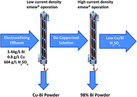
As suggested from the previous experiments, if the cell current (e.g. cathode potential) is set to a suitable level, the copper could be initially removed with some contamination and then maybe the bismuth could be extracted using a higher current setting. This could result in an improvement in current efficiency and productivity of the cell. Therefore, a two-stage treatment was examined to selectively remove the Cu and then the Bi from the industrial solution. In the first stage, 75 A m−2 was applied for 90 minutes. The resulting powder deposit was removed. Then, 350 A m−2 was applied for 20 minutes in the second stage. A second powder was then removed. Using the two stage treatment, 97.8% of copper and 93.4% of bismuth were removed, and a reasonable current efficiency of 61.6% was obtained. The first step produced a powder that consisted of metallic copper and bismuth and no detectible Cu2O. This powder could be used to produce a Cu–Bi master alloy to improve the machinability of brass.24 The second step produced a high purity Bi powder (98%) which could serve as a feed stock to a bismuth refinery. The two stage process appears to offer a more energy efficiency process with higher value products.

4. Conclusions

A novel electrowinning process to recover bismuth and copper from an industrial copper electrorefining effluent using an emew® cell was developed. Bismuth powder can be electrowon from the synthetic and industrial Bi(III)-containing concentrated sulfuric acid solutions using an emew® cell. By adjusting the applied current, the electrowinning performance of the cell could be altered. The co-deposition of Cu and Bi was achieved at high current conditions in the emew® cell, but the current efficiency was low (<30%). Low current operation facilitated Cu powder generation over the formation of Cu2O and Bi metal while increasing current efficiency. The improvement in current efficiency appears to occur by reducing the cathode overpotential and inhibiting hydrogen evolution. The current inefficiency does not appear to be related to the re-solution of the powders produced.

A two-stage emew® cell process was demonstrated to produce higher value products with greater energy efficiency. The first stage of the process used a low current setting (75 A m−2) for 90 minutes to remove most of the copper. In the second stage, a high current (350 A m−2) was applied for 20 minutes to deposit bismuth. The two stage process produced two products (Cu–Bi powder and high purity Bi powder) which are of suitable purity for use as a master alloy for lead-free machinable brass and a bismuth feed stock while achieving an overall current efficiency of 62%.

Acknowledgements

The authors would like to thank ASARCO for supplies, funds and permission to publish this work. The Materials Research Center is acknowledged for providing supplemental funds for physical characterization of the powders.

References

  1. A. Agrawal, S. Kumari and K. K. Sahu, Ind. Eng. Chem. Res., 2009, 48(13), 6145–6161 CrossRef CAS.
  2. J. Hait, R. K. Jana and S. K. Sanyal, Ind. Eng. Chem. Res., 2004, 43(9), 2079–2087 CrossRef CAS.
  3. M. L. Ballinas, E. D. San Miguel, M. Munoz and J. Gyves, Ind. Eng. Chem. Res., 2003, 42(3), 574–581 CrossRef.
  4. F. Xiao, J. Mao, D. Cao, X. Shen and A. A. Volinsky, Hydrometallurgy, 2012, 71, 125–126 Search PubMed.
  5. M. Gorgievski, D. Bozic, V. Stankovic and G. Bogdanovic, J. Hazard. Mater., 2009, 170, 716–721 CrossRef CAS PubMed.
  6. N. V. Deorkar and L. L. Tavlarides, A chemically bonded adsorbent for separation of antimony, copper and lead, Hydrometallurgy, 1997, 46, 121–135 CrossRef CAS.
  7. A. J. Bard, R. Parsons and J. Jordan, Standard potentials in aqueous solutions, IUPAC, Marcel Dekker, New York, USA, 1985 Search PubMed.
  8. K. Ando and N. Tsuchida, JOM, 1997, 49, 49–51 CrossRef CAS PubMed.
  9. J. E. Hoffmann, JOM, 2004, 56, 30–33 CrossRef CAS PubMed.
  10. E. Sandnes, M. E. Williams, U. Bertocci, M. D. Vaudin and G. R. Stafford, Electrochim. Acta, 2007, 52, 6221–6228 CrossRef CAS PubMed.
  11. J. T. Hinatsu and F. R. Foulkes, J. Electrochem. Soc., 1989, 136, 125–132 CrossRef CAS PubMed.
  12. J.-G. Yang, C.-B. Tang, S.-H. Yang, J. He and M. T. Tang, Hydrometallurgy, 2009, 100, 5–9 CrossRef CAS PubMed.
  13. L. Iberhan and M. Wisniewski, Hydrometallurgy, 2002, 63, 23–30 CrossRef CAS.
  14. P. A. Treasure, Electrolytic zinc recovery in the emew cell, Proceedings of the TMS Fall Extraction and Processing Conference, Missouri: The Minerals, Metals and Materials Society, 2000, 185–191.
  15. V. Escobar, T. Treasure and R. E. Dixon, High current density emew copper electrowinning, Proceedings of the TMS Fall Extraction and Processing Conference, Chicago: The Minerals, Metals and Materials Society, 2003, 1369–1380.
  16. S. Wang, JOM, 2008, 60, 41–45 CrossRef CAS.
  17. W. Jin, H. Du, S. Zheng, H. Xu and Y. Zhang, J. Phys. Chem. B, 2010, 114(19), 6542–6548 CrossRef CAS PubMed.
  18. W. Jin, M. S. Moats, S. Zheng, H. Du, Y. Zhang and J. D. Miller, Electrochim. Acta, 2011, 56, 8311–8318 CrossRef CAS PubMed.
  19. W. Jin, M. S. Moats, S. Zheng, H. Du, Y. Zhang and J. D. Miller, J. Phys. Chem. B, 2012, 116, 7531–7537 CrossRef CAS PubMed.
  20. T. Berzins and P. Delahay, J. Am. Chem. Soc., 1953, 75, 555–559 CrossRef CAS.
  21. B. Mandal and N. Ghosh, J. Hazard. Mater., 2010, 182, 363–370 CrossRef CAS PubMed.
  22. K. R. Chu, E. Lee, S. H. Jeong and E.-S. Park, Arch. Pharmacal Res., 2012, 35, 1187–1195 CrossRef CAS PubMed.
  23. K. J. Cathro, J. Electrochem. Soc., 1992, 139, 2186–2192 CrossRef CAS PubMed.
  24. S. Kuyucak and M. Sahoo, Can. Metall. Q., 1996, 35, 1–15 CrossRef PubMed.

This journal is © The Royal Society of Chemistry 2015
Click here to see how this site uses Cookies. View our privacy policy here.