Sn–Co nanoparticles encapsulated in grid-shell carbon spheres, applied as a high-performance anode material for lithium-ion batteries

Bo Zhang, Xiao-Shan Li, Chun-Ling Liu*, Zong-Huai Liu and Wen-Sheng Dong*
Key Laboratory of Applied Surface and Colloid Chemistry (SNNU), MOE, School of Chemistry and Chemical Engineering, Shaanxi Normal University, Xi'an 710062, China. E-mail: clliutt@snnu.edu.cn; wsdong@snnu.edu.cn; Fax: +86-29-81530806; Tel: +86-29-81530806

Received 5th May 2015 , Accepted 4th June 2015

First published on 4th June 2015


Abstract

A novel composite comprising Sn–Co nanoparticles encapsulated in grid-shell carbon spheres was synthesized. The composite comprised homogeneous grid-shell carbon spheres with a size of ∼1 μm and a shell thickness of ∼100 nm; SnCo and SnO2 nanoparticles with an average size of ∼16 nm were uniformly embedded in the shells and internal grids of the carbon spheres. This composite showed high capacity, good rate performance and excellent capacity retention when it was applied as an anode material for lithium-ion batteries.
1. Introduction

Lithium-ion batteries (LIBs) are typically used as the power source for portable electronic devices, and are also considered as candidate power sources for electric vehicles and hybrid electric vehicles.1 Graphite is the current choice for the anode materials in commercial LIBs, owing to its long cycle life, abundance, and relatively low cost. However, graphite anode materials have some disadvantages, including a low theoretical capacity (372 mA h g−1), and questions regarding their safety.2 Increasing interest has therefore been focused on the development of alternative anode materials with high energy/power density, a long cycle life, low cost, and enhanced safety.

In the last decade, metallic tin or tin dioxide has been extensively investigated as a potential candidate for negative electrode material in LIBs, because of their much higher specific capacity compared with that of graphite.3,4 Moreover, tin-based anodes are less reactive than graphite anodes, because of their higher operating voltage, thus improving the safety of batteries during rapid charge/discharge cycles.4,5 However, a large obstacle prevents the application of tin-based anode materials; metallic tin or tin dioxide suffer from large variations in their volume during Li insertion/extraction cycles, leading to pulverization of the electrode, and a very rapid deterioration in the capacity.6,7 To date, various strategies have been employed to overcome this problem; one of these methods involves the dispersion of nanometer-sized particles of metallic tin or tin dioxide in a carbon matrix,5,7–17 where the carbon acts as both a structural buffer and an electroactive material. However, because of the low melting point of tin (232 °C), it remains a challenge to uniformly disperse tin nanoparticles in a carbon matrix.17 Another promising approach involves the use of inter metallic compounds, for example Sn–Co,18 Sn–Cu,19 Sn–Sb–Ni,20 or Sn–Co–C.21–40 These materials exhibit improved cycling performance because of the buffering effect of the inactive components in the alloys, which provides structural stability during cycling. Among these Sn-base materials, Sn–Co–C composites, in particular, have attracted much attention, since the Sony Company used this material for commercial battery applications. Commercial Sn–Co–C anodes have been extensively studied, and stable reversible capacities of approximately 400–450 mA h g−1 have been achieved over 30 cycles at 0.5 mA cm−2.21,22 However, the achievable capacity remains limited, and cannot meet the requirements of next-generation electrodes for LIBs.36

In a previous study, we prepared a nanostructured Sn0.31Co0.09C0.6 composite via a simple solution polymerization, followed by pyrolysis in a nitrogen atmosphere. This material delivered an initial reversible capacity of 719 mA h g−1 at a current density of 50 mA g−1, and after 100 cycles it retained a capacity of 706.7 mA h g−1 when applied as an anode material for rechargeable LIBs.37 However, the kinetics of the charge/discharge process must be improved further to meet the requirements for use at large current densities.

In this study, a novel composite consisting of Sn–Co nanoparticles embedded in grid-shell carbon spheres (SnCo/GSCS) was synthesized for the first time. The change in the volume of the Sn–Co nanoparticles was confined inside the spherical shell-grids of the amorphous carbon, and the Sn–Co particles were able to (in principle) make full contact with the electrolyte filling the spaces in the grid-shell carbon spheres. This novel nanostructured material showed high initial charge capacities at both low and high current densities and an excellent cycling stability when it was applied as an anode material for rechargeable LIBs.

2. Experimental methods

2.1 Synthesis of materials

All the chemicals were of analytical reagent grade, and were used without further purification.

Sn–Co colloids were prepared according to the following procedure. In a typical preparation, 0.49 g of SnCl2·2H2O, 0.1722 g of CoCl2·6H2O, and 0.1 g of PVA (Mw 10[thin space (1/6-em)]000 from Aldrich, 80% hydrolyzed), which acted as a protecting agent, were added to 25 mL of deionized water, and this mixture was stirred for a few minutes to form a pink transparent solution. Then, 0.8312 g of NaBH4 was added dropwise to the reaction system, and the temperature was maintained at 0–5 °C using an ice-water bath. After continuous magnetic stirring for 2 h, the resultant nanoparticles (Sn–Co) were collected via centrifugation, copious washing with deionized water, and drying under vacuum at 50 °C for 12 h.

The scheme for the synthesis of the Sn–Co/GSCS composite is shown in Scheme 1. Sn–Co/polymerspheres were prepared via the polymerization of 2,4-dihydroxybenzoic acid (DA) and formaldehyde, using lysine as a polymerization catalyst in the presence of the Sn–Co nanoparticles. The non-ionic surfactant F108 (Sigma-Aldrich) was used as an additive to achieve a homogeneous spherical product. In a typical synthesis, 1.8 g of F108 was dissolved in 300 mL of ethanol, and 0.175 g of the Sn–Co nanoparticles was then dispersed in the system under vigorous stirring; the solution temperature was fixed at 80 °C. DA (1.68 g) and L-lysine (0.288 g) were then added to the above solution under vigorous stirring. After the addition of formaldehyde (1.79 g, 37 wt%), the clear solution became turbid and white in color, then beige, and then orange, with increasing time. After 36 h, the yellow-green polymer spheres (Sn–Co/PS) were collected via filtration, and then immersed in distilled water (350 mL) at 80 °C for 3 h. During this process, the salt-like complex formed by the reaction of the amine groups of the lysine with the carboxylic acid groups of the DA was partially dissolved from the interior of the Sn–Co/PS.41 Consequently, Sn–Co/PS particles with a grid-shell structure were obtained. The grid-shell Sn–Co/PS particles were then dried and pyrolyzed at 600 °C for 1 h, in N2. Finally, the Sn–Co/GSCS composite was obtained.


image file: c5ra08244g-s1.tif
Scheme 1 Schematic of the process used for the preparation of the Sn–Co/GSCS composite.

2.2 Characterization of materials

Scanning electron microscopy (SEM) and energy dispersive X-ray analysis (EDAX) were performed on a Philips-FEI Quanta 200 microscope operated at 20 kV. The crystal structure of the as-prepared sample was characterized using powder X-ray diffraction (XRD), which was performed on a Rigaku D/MAX-IIIX-ray diffractometer (35 kV, 40 mA), using a CuKα source. The diffraction patterns were taken from 10° to 80°, using a scan rate of 8° min−1. The microstructure was characterized using high-resolution transmission electron microscopy (JEM-2100; JEOL). The specific surface area and pore size distribution of the samples were determined using N2 (77 K) adsorption measurements, which were performed using a Micromeritics ASAP2020M system.

2.3 Electrochemical measurements

The working electrode consisted of 80 wt% active material, 10 wt% acetylene black (Super-P), and 10 wt% polyterafluoroethylene. Pure lithium was used for the counter and reference electrodes, and a polypropylene film (Celgard 2400) was used as a separator. The electrolyte consisted of 1.0 M LiPF6 dissolved in a mixed solution of ethylene carbonate (EC) and dimethyl carbonate (1[thin space (1/6-em)]:[thin space (1/6-em)]1, by weight). The specific conductivity of the electrolyte solution was 11.5 ms cm−1, which was measured using a conductivity meter. The cells (CR2032 coin type) were assembled in an argon-filled glove box, and were charged and discharged at a constant current density of 100 mA g−1 (unless otherwise stated), between cut-off potentials of 3.0 V and 0.005 V, using a LAND CT2001A cell test apparatus. Cyclic voltammetry (CV) measurements were performed on an electrochemistry workstation (Autolab PGSTAT302N), using a scan rate of 0.1 mV s−1, within the range of 0.005–3.0 V. The impedance spectroscopy measurements were performed on Autolab PGSTAT302N in the frequency range from 10 mHz to 100 kHz.

3. Results and discussion

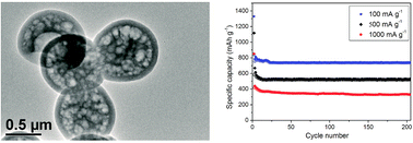
To elucidate the morphology and structure of the samples, SEM and TEM measurements were performed. As shown in Fig. 1A, the Sn–Co/GSCS prepared via the polymerization of 2,4-dihydroxybenzoic acid and formaldehyde, catalyzed by lysine and in the presence of the Sn–Co nanoparticles, displayed a spherical shape, with a diameter of ∼1.0 μm. Energy-dispersive X-ray spectrometry analysis (Fig. 1B) indicated that this sample contained 55.6% of C, 18.9% of Sn, 2.2% of Co, and 23.3% of O. The TEM image in Fig. 1C confirmed that the sample consisted of grid-shell carbon spheres with an outer shell thickness of ∼100 nm. Sn–Co nanoparticles with an average diameter of 16 nm were homogeneously embedded in the shells and internal grids of the carbon spheres (Fig. 1D).
image file: c5ra08244g-f1.tif
Fig. 1 SEM image (A), EDAX pattern (B), and TEM images (C and D), for SnCo/GSCS.

The N2 adsorption–desorption isotherms and pore size distribution of CoSn/GSCS are shown in Fig. 2A. The isotherm of the CoSn/GSCS sample showed typical characteristics of microporous carbons. The adsorbed volume increased sharply when p/p0 was ≤0.05, and then remained nearly constant after p/p0 was ≥0.1; the knee of the isotherm was sharp and the plateau was almost horizontal. The sample had a BET surface area of 486 m2 g−1, a micropore surface area of 408 m2 g−1, a total pore volume of 0.198 m3 g−1. The XRD pattern for the Sn–Co/GSCS sample is shown in Fig. 2B. The broad peak at approximately 23.8° corresponded to the amorphous carbon in the product. The sharp peaks at 28.5°, 33.8°, 40.2°, 42.4°, 45.1°, 57.6°, and 71.2° were assigned to CoSn alloy (JCPDS no. 02-0559). The peaks at 26.5°, 33.8°, 37.9°, 51.7°, 55.2°, 57.6°, 64.9°, and 71.2° were assigned to SnO2 (JCPDS no. 41-1445). The results showed that the sample contained amorphous carbon, SnCo alloy, and SnO2.


image file: c5ra08244g-f2.tif
Fig. 2 N2 sorption isotherm (A), corresponding pore size distribution (A, insert), and XRD pattern (B) for SnCo/GSCS.

To test the potential of the Sn–Co/GSCS composite anode for its application in lithium batteries, we investigated the electrochemical properties with respect to Li insertion/extraction. Fig. 3A shows CVs for the Sn–Co/GSCS anode. The cyclic voltammetry profiles revealed that there was a substantial difference between the first cycle and the subsequent cycles. Two cathodic peaks were observed during the first cathodic scan (the peaks were centered at 1.50 and 0.75 V, respectively), but were not present in the corresponding anodic cycles. The two peaks were ascribed to the formation of the solid electrolyte interface film on the surface of the Sn–Co/GSCS electrode and the passivation of the carbon.23,34 Peaks at voltages lower than 0.5 V can be associated with the electrochemical reduction of SnO2 to Sn, the reaction of Sn and SnCo alloy with lithium to form an LixSn alloy, and the insertion of Li into the carbon matrix to form LiCx.4,15,23,42 During the anodic process (corresponding to the Li dealloying process), there were two anodic current peaks. One was at approximately 0.20 V and was attributed to the deintercalation of Li from LiCx. The other peak was at approximately 0.75 V, and was associated with the dealloying reaction from LixSn to Li and Sn.34,43 The CV curves for the Sn–Co/GSCS anode in the subsequent two cycles almost overlapped, suggesting an excellent reversibility.


image file: c5ra08244g-f3.tif
Fig. 3 CV curves (A), discharge–charge curves at a current density of 100 mA g−1 (B), and cycling performance at various current densities (C), and impedance spectra (D), for Sn–Co/GSCS.

The charge (Li+ extraction) and discharge (Li+ insertion) curves for the as-prepared Sn–Co/GSCS sample are shown in Fig. 3B. In the first cycle, the Sn–Co/GSCS composite electrode delivered a large discharge capacity of 1330 mA h g−1, and the corresponding charge capacity was 840.6 mA h g−1. There was a large irreversible capacity in the first cycle, which led to a relatively low coulombic efficiency of 63.2%. The irreversible capacity most likely resulted from two factors: the formation of a solid electrolyte interface film on the surface of the electrode; and the presence of abundant unsaturated carbon atoms in the sample, which may have catalyzed the decomposition of the electrolytes.8 From the second cycle onward, the Sn–Co/GSCS composite anode delivered a charge capacity near its discharge capacity, with a coulombic efficiency of higher than 90%. After five cycles, the coulombic efficiency increased to 97% and was stable thereafter, indicating that the newly formed interface was stable during the cycling.

Fig. 3C shows the cycling performance of the composite anode. The Sn–Co/GSCS anode delivered an excellent cyclicstability, and a large reversible capacity. The Sn–Co/GSCS composite electrode exhibited a high initial charge capacity of 840.6 mA h g−1 at 100 mA g−1, and even after 200 cycles the electrode maintained a capacity of 734 mA h g−1, giving a high capacity retention of 87.3%. When the current density was increased to 500 mA g−1, the electrode still delivered an initial charge capacity of 583.2 mA h g−1, and after 200 cycles the electrode maintained a capacity of 522.7 mA h g−1, giving a high capacity retention of 89.6%. At a high rate of 1000 mA g−1, the electrode still delivered an initial charge capacity of 416 mA h g−1, confirming that the electrode had a good rate performance. After 200 cycles, the electrode retained a capacity of 335.6 mA h g−1. The electrode was tested for a further 800 cycles at a current density of 1000 mA g−1, and after 800 cycles it still retained a capacity of 335 mA h g−1, confirming that the electrode had excellent cycling stability at large current densities.

For further explaining above results, AC impedance spectroscopy was employed to analyze the performance of the Sn–Co and Sn–Co/GSCS composite anodes. Fig. 3D presents the impedance spectra of the anodes from 10 mHz to 100 kHz. The impedance spectra had the feature: a medium-to-high frequency depressed semicircle and an inclined low frequency line, which corresponded well to the results of previously reported Sn anode.44,45 The inclined line in the low frequency region represented the lithium diffusion impedance, and the depressed semicircle suggested an overlap between the SEI film and an interfacial charge transfer impedance. The results of impedance spectra measured for the Sn–Co and Sn–Co/GSCS composite anodes revealed that the total SEI and interfacial charge transfer impedance were quite distinct among them. Undoubtedly, the electric conductivity and ionic conductivity of Sn–Co/GSCS were much higher than those of Sn–Co. This result is in agreement with the superior rate capability of the Sn–Co/GSCS composite since charge transfer process is the rate-determining step for conversion reactions.

On the basis of the preceding results, the excellent cycling ability and high capacity of the Sn–Co/GSCS composite electrode likely resulted from the following factors: first, the porous grid-shell carbon spheres with good electronic conductivity and high surface area likely provided a higher number of active sites for Li+ storage, a large electrode/electrolyte contact area, and a short path length for Li+ transport. Second, the porous grid-shell carbon spheres, which had an abundance of void space, likely allowed only a limited change in volume in the local environment, and the carbon layer coated on the Sn–Co particles had enough mechanical strength to act as a structural buffer preventing the disintegration and aggregation of the Sn particles. Third, the nano-sized SnCo alloy and SnO2 particles were embedded in the shell and internal grid of the carbon spheres, which effectively increased the charge-transfer properties and shortened the transport length for both electrons and lithium ions. The above observations, supported by the experimental results of this study, confirm the high capacity and excellent cycling performance of the Sn–Co/GSCS composite electrode, and its potential as a next-generation electrode material for LIBs.

4. Conclusions

A novel Sn–Co/GSCS composite with SnCo and SnO2 nanoparticles embedded in the shells and internal grids of carbon spheres was prepared via the polymerization of 2,4-dihydroxybenzoic acid and formaldehyde, using lysine as a polymerization catalyst in the presence of the Sn–Co nanoparticles, and subsequent pyrolysis. The composite exhibited a highly reversible Li storage capacity, excellent cyclability, and good rate performance when it was applied as an anode material for LIBs. The method used for the synthesis of the Sn–Co/GSCS composite will be generally applicable to a wide variety of charges in metal or metal oxide particles, and will facilitate the production of various composites—including Sn/GSCS, Si/GSCS, Fe2O3/GSCS, and Co3O4/GSCS—for a variety of purposes.

Acknowledgements

The authors gratefully acknowledge financial support from the Program for Key Science and Technology Innovation Team of Shaanxi Province (2012KCT-21), and the Program for Changjiang Scholars and Innovative Research Team in University of China (IRT_14R33), and the Fundamental Research Funds for the Central Universities (GK201501007).

References

  1. B. Scrosati and J. Garche, J. Power Sources, 2010, 195, 2419–2430 CrossRef CAS PubMed.
  2. M. Winter, J. O. Besenhard, M. E. Spahr and P. Novák, Adv. Mater., 1998, 10, 725–763 CrossRef CAS.
  3. Y. Idota, T. Kubota, A. Matsufuji, Y. Maekawa and T. Miyasaka, Science, 1997, 276, 1395–1397 CrossRef CAS.
  4. M. Winter and J. O. Besenhard, Electrochim. Acta, 1999, 45, 31–50 CrossRef CAS.
  5. W. M. Zhang, J. S. Hu, Y. G. Guo, S. F. Zheng, L. S. Zhong, W.-G. Song and L.-J. Wan, Adv. Mater., 2008, 20, 1160–1165 CrossRef CAS PubMed.
  6. H. Li, L. Shi, Q. Wang, L. Chen and X. Huang, Solid State Ionics, 2002, 148, 247–258 CrossRef CAS.
  7. M. Noh, Y. Kwon, H. Lee, J. Cho, Y. Kim and M. G. Kim, Chem. Mater., 2005, 17, 1926–1929 CrossRef CAS.
  8. M.-Y. Li, Y. Wang, C.-L. Liu, C. Zhang and W.-S. Dong, J. Electrochem. Soc., 2012, 159, A91–A97 CrossRef CAS PubMed.
  9. B. Guo, J. Shu, K. Tang, Y. Bai, Z. Wang and L. Chen, J. Power Sources, 2008, 177, 205–210 CrossRef CAS PubMed.
  10. S. Yang, H. Song and X. Chen, J. Power Sources, 2007, 173, 487–494 CrossRef CAS PubMed.
  11. G. Wang, B. Wang, X. Wang, J. Park, S. Dou, H. Ahn and K. Kim, J. Mater. Chem., 2009, 19, 8378–8384 RSC.
  12. J. Liang, W. Wei, D. Zhong, Q. Yang, L. Li and L. Gu, ACS Appl. Mater. Interfaces, 2012, 4, 454–459 CAS.
  13. B. Lee, S. C. Han, M. Oh, M. S. Lah, K.-S. Sohn and M. Pyo, Electrochim. Acta, 2013, 113, 149–155 CrossRef CAS PubMed.
  14. Z. Li, G. Wu, D. Liu, W. Wu, B. Jiang, J. Zheng, Y. Li, J. Li and M. Wu, J. Mater. Chem. A, 2014, 2, 7471–7477 CAS.
  15. M.-Y. Li, C.-L. Liu, Y. Wang and W.-S. Dong, J. Electrochem. Soc., 2011, 158, A296–A301 CrossRef CAS PubMed.
  16. X. Qian, T. Hang, G. Ran and M. Li, RSC Adv., 2015, 5, 31275–31281 RSC.
  17. G. Cui, Y. S. Hu, L. Zhi, D. Wu, I. Lieberwirth, J. Maier and K. Müllen, Small, 2007, 3, 2066–2069 CrossRef CAS PubMed.
  18. H. Kim and J. Cho, J. Electrochem. Soc., 2007, 154, A462–A466 CrossRef CAS PubMed.
  19. J. Wolfenstine, S. Campos, D. Foster, J. Read and W. K. Behl, J. Power Sources, 2002, 109, 230–233 CrossRef CAS.
  20. H. Guo, H. Zhao, X. Jia, J. He, W. Qiu and X. Li, J. Power Sources, 2007, 174, 921–926 CrossRef CAS PubMed.
  21. Q. Fan, P. J. Chupas and M. S. Whittingham, Electrochem. Solid-State Lett., 2007, 10, A274–A278 CrossRef CAS PubMed.
  22. R. Zhang and M. S. Whittingham, Electrochem. Solid-State Lett., 2010, 13, A184–A187 CrossRef CAS PubMed.
  23. J. Hassoun, S. Panero, G. Mulas and B. Scrosati, J. Power Sources, 2007, 171, 928–931 CrossRef CAS PubMed.
  24. J. Hassoun, G. Mulas, S. Panero and B. Scrosati, Electrochem. Commun., 2007, 9, 2075–2081 CrossRef CAS PubMed.
  25. G. F. Ortiz, R. Alcántara, I. Rodríguez and J. L. Tirado, J. Electroanal. Chem., 2007, 605, 98–108 CrossRef CAS PubMed.
  26. S. I. Lee, S. Yoon, C. M. Park, J. M. Lee, H. Kim, D. Im, S. G. Doo and H. J. Sohn, Electrochim. Acta, 2008, 54, 364–369 CrossRef CAS PubMed.
  27. A. D. W. Todd, R. E. Mar and J. Dahn, J. Electrochem. Soc., 2007, 154, A597–A604 CrossRef CAS PubMed.
  28. R. B. Lewis, A. Timmons, R. E. Mar and J. R. Dahn, J. Electrochem. Soc., 2007, 154, A213–A216 CrossRef CAS PubMed.
  29. P. P. Ferguson, A. D. W. Todd and J. R. Dahn, Electrochem. Commun., 2008, 10, 25–31 CrossRef CAS PubMed.
  30. P. P. Ferguson, M. L. Martine, A. E. George and J. R. Dahn, J. Power Sources, 2009, 194, 794–800 CrossRef CAS PubMed.
  31. P. P. Ferguson, A. D. W. Todd and J. R. Dahn, Electrochem. Commun., 2010, 12, 1041–1044 CrossRef CAS PubMed.
  32. J. Li, D. B. Le, P. P. Ferguson and J. R. Dahn, Electrochim. Acta, 2010, 55, 2991–2995 CrossRef CAS PubMed.
  33. Z. Chen, J. Qian, X. Ai, Y. Cao and H. Yang, J. Power Sources, 2009, 189, 730–732 CrossRef CAS PubMed.
  34. T. Huang, Y. Yao, Z. Wei, Z. Liu and A. Yu, Electrochim. Acta, 2010, 56, 476–482 CrossRef CAS PubMed.
  35. L. Huang, J. S. Cai, Y. He, F. S. Ke and S. G. Sun, Electrochem. Commun., 2009, 11, 950–953 CrossRef CAS PubMed.
  36. Y. Gu, F. Wu and Y. Wang, Adv. Funct. Mater., 2013, 23, 893–899 CrossRef CAS PubMed.
  37. M.-Y. Li, C.-L. Liu, M.-R. Shi and W.-S. Dong, Electrochim. Acta, 2011, 56, 3023–3028 CrossRef CAS PubMed.
  38. P. P. Ferguson, A. D. W. Todd, M. L. Martine and J. R. Dahn, J. Electrochem. Soc., 2014, 161, A342–A347 CrossRef CAS PubMed.
  39. P. Chen, L. Guo and Y. Wang, J. Power Sources, 2013, 222, 526–532 CrossRef CAS PubMed.
  40. X. Liu, J. Xie, H. Zhao, P. Lv, K. Wang, Z. Feng and K. Świerczek, Solid State Ionics, 2015, 269, 86–92 CrossRef CAS PubMed.
  41. A.-H. Lu, W.-C. Li, G.-P. Hao, B. Spliethoff, H.-J. Bongard, B. B. Schaack and F. Schüeth, Angew. Chem., Int. Ed., 2010, 49, 1615–1618 CrossRef CAS PubMed.
  42. C. Tan, G. Qi, Y. Li, J. Guo, X. Wang, D. Kong, H. Wang and S. Zhang, J. Alloys Compd., 2013, 574, 206–211 CrossRef CAS PubMed.
  43. K. Ui, S. Kikuchi, Y. Jimba and N. Kumagai, J. Power Sources, 2011, 196, 3916–3920 CrossRef CAS PubMed.
  44. X. Zhao, Z. Xia and D. Xia, Electrochim. Acta, 2010, 55, 6004–6009 CrossRef CAS PubMed.
  45. F. Nobili, M. Mancini, S. Dsoke, R. Tossici and R. Marassi, J. Power Sources, 2010, 195, 7090–7097 CrossRef CAS PubMed.

This journal is © The Royal Society of Chemistry 2015
Click here to see how this site uses Cookies. View our privacy policy here.