DOI:
10.1039/C5RA08172F
(Paper)
RSC Adv., 2015,
5, 58959-58965
Bistable polymer-dispersed cholesteric liquid crystal thin film enabled by a stepwise polymerization
Received
4th May 2015
, Accepted 24th June 2015
First published on 24th June 2015
Abstract
In this paper, by using a novel polymer network and an ion-doped cholesteric liquid crystal (ChLC) with negative dielectric anisotropy, we successfully fabricated a bistable polymer-dispersed liquid crystal (PDLC) thin film by the optically-induced polymerization of acrylate monomers followed by the thermal curing of epoxy groups. The stepwise processes not only enable an enhancement in the mechanical properties of PDLC films but also a stabilization of cholesteric textures by polymer networks. The bistable memory effects came from the anchoring properties of polymer networks formed within the microdroplets of PDLCs. The devices prepared from the films can be reversibly switched between a transparent state and an opaque state by an electric field. When the electric field is removed, the states are retained. Therefore, the devices are highly energy efficient.
1. Introduction
Polymer-dispersed liquid crystal (PDLC) films can be used as an important class of electro-optical materials for making large and flexible displays, optical shutters and switchable windows.1–5 In recent years, bistable liquid crystal (LC) devices have received considerable attention for use in light shutters because of their unique electro-optic properties.6–8 Unlike traditional PDLC devices, a bistable mode PDLC need not be placed in a sustained electric field to maintain its two optical states; it is therefore better suited for use as an energy-saving light shutter. They have the advantages of fascinating visual effects, no mechanically moving parts and instant switching. They have been used for architectural and greenhouse windows for privacy and energy flow control.9–11 Recently, more research efforts have been devoted to producing bistable LC technology. Among these, methods based on cholesteric liquid crystals (ChLCs) are of great interest because they exhibit strong bistability and have the ability to be passively multiplexed, giving them potential applications as low-power and low-cost devices, switchable storage devices, and electronic paper.12–15 As is known, an electric field can switch an ion-doped ChLC with negative dielectric anisotropy between two stable states. The scattering focal conic (FC) state is obtained as the LC relaxes from the electrohydrodynamic instability known as the dynamic light scattering, induced by a low frequency electric field. The clear state is obtained as a planar (P) aligned texture after the application of a high frequency electric field.16
Generally, polymer-stabilized LC (PSLC) was employed as an optimal method to make bistable LC devices. In PSCT, the liquid-crystalline material represents the continuous matrix, while a small amount (≈5 wt%) of a crosslinked polymer is dispersed in the anisotropic fluid.17 However, such a device has poor mechanical strength. Consequently, the addition of polymer network infrastructure is required to provide mechanical stability to the LC devices. Epoxy resins have found a myriad of applications due to their good thermal and chemical resistance, superior mechanical properties, and excellent adhesion to a variety of substrates. Specifically, most epoxy resins are employed as mutually reactive two component mixtures consisting of a multifunctional epoxymonomers and a coreactant termed “multifunctional amines”.18,19
In this paper, bistable PDLC films were prepared by first photo-curing through the acrylate groups, and then thermally curing the epoxy groups. The dual-curing capability not only allows increased mechanical properties but also the cholesteric texture can be stabilized by polymer networks. In the cells, the initial P orientation (helical axis perpendicular to the substrates) of a long pitch cholesteric (P = several micrometers) is stabilized by the network and a texture transition to the scattering FC state is induced by a low frequency electric fields. The application of a high frequency electric field causes a rapid reorientation back to the P configuration. With proper polymer networks, both the P and FC states were stabilized at zero voltage. Switching by electric field application thus occurs from transparent to scattering, or black to white. This is the first report of bistable PDLC films via two different polymerization steps.
2. Experimental
2.1 Materials
The LC used in the study was HNG 726200-100 (TNI = 373.2 K, Δε = −4.0, Jiangsu Hecheng Display Technology Co. Ltd), the chiral dopant CB15 (Merck Co., Ltd) was used. 3,5,5-Trimethylhexylacrylate (TMHA), isobutyl methacrylate (IBMA), 1,4-butanedioldiacrylate (BDDA) and polyethylene glycol (600) diacrylate (PEGDA600) were used as ultraviolet (UV) initiated free-radical curable monomers (Tokyo Chemical Industry Co., Ltd). The photoinitiator was Irgacure 651 (Ciba-Geigy). Epoxies of 4,4′-methylenebis(N,N-diglycidylaniline) (TGMDA, TCI (Shanghai) Development Co., Ltd) cured with a stoichiometric amount of the amine curing agent biscyclohexanamine (PACM, TCI (Shanghai) Development Co., Ltd). Hexadecyl trimethyl ammonium bromide (CTAB, Sinopharm Chemical Reagent Co. Ltd) salt was employed. The chemical structures and some physical properties of the materials are shown in Fig. 1.
 |
| Fig. 1 Chemical structures of some materials used. | |
2.2 Sample preparation
The compositions of the samples were prepared and vigorously stirred until a homogeneous mixture formed. Then, the mixture was sandwiched between two pieces of indium-tin-oxide coated glass substrates by capillary filling into LC cell. The film thickness was controlled by 30.0 ± 1.0 μm thick polyester spacers. The samples were irradiated for polymerisation by a UV lamp (365 nm 35 W Hg lamp, PS135, UV Flood, Stockholm, Sweden) for 10.0 min at 318.2 K. The curing intensity was 1.0 mW cm−2. After that, thermal curing was carried out at 323.2 K for 6 hours with applying an ac field at frequency of 5000 Hz and voltage of 50 V. An open hot-stage was used to control temperature during the thermal-cure. The compositions of samples in the study were listed in Table 1.
Table 1 The compositions of the samples studied
Sample |
TMHA/BDDA/PEGDA600/IBMA/Irgacure 651/TGMDA/PACM/HNG 726200-100/CB15/CTAB (wt%) |
1 |
3.8/3.8/7.6/3.8/0.9/0.0/0.0/78.0/2.0/0.1 |
2 |
3.8/3.8/7.6/3.8/0.9/0.4/0.4/77.2/2.0/0.1 |
3 |
3.8/3.8/7.6/3.8/0.9/0.8/0.8/76.4/2.0/0.1 |
4 |
3.8/3.8/7.6/3.8/0.9/1.2/1.2/75.6/2.0/0.1 |
5 |
3.8/3.8/7.6/3.8/0.9/1.6/1.6/74.8/2.0/0.1 |
6 |
3.8/3.8/7.6/3.8/0.9/2.0/2.0/74.0/2.0/0.1 |
2.3 Measurements
The morphology of the samples was observed by scanning electron microscopy (SEM) (ZEISS, EVO18, Germany). The samples were first separated and dipped into cyclohexane for four days at room temperature to extract the LCs molecules, followed by drying for 12 hours under vacuum. After the samples were sputtered with carbon, the microstructure of the polymer network was observed under SEM. The optical textures of the samples used were studied by polarizing optical microscopic (POM) (Olympus BX-51) equipped with function generator (Tektronix AFG3102) and RF Power Amplifier (NF HSA4051). The spectra of selective transmission were obtained by UV/VIS/NIR spectrophotometer (JASCO V-590), while the transmittance of the blank cell was normalized as 100%.
3. Results and discussion
3.1 Proposed mechanism of bistable PDLC devices
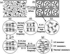
As Fig. 2 shows a schematic of the bistable PDLC films from photo- and thermally-induced processes, which can be switched between a transparent state and an opaque state by electric field. The states can be sustained without applying electric field. Therefore, this device is highly energy efficient. The film combines the advantages of both PDLC and PSCT. The molecular arrangement of the used ChLC with negative dielectric anisotropy tends to be perpendicular to the applied field. The pitch of the ChLC is about 2.5 μm. The monomer mixtures were irradiated by UV light firstly. As shown in Fig. 2(b) photo-polymerization induced phase separation forming LC droplets with a diameter on the order of several micrometers in the processes. There were mixing of low-molecular-weight and thermally curable monomers in the LC droplets appearing light scattering state. The scattering state was the FC state where the LC exists in randomly oriented poly-domains as shown in Fig. 2(c). Then, the cell was cured by hot-stage to polymerize the thermal monomers. During polymerization, a sufficiently high frequency voltage was applied across the cell and the mixture was in the P texture where the LC and monomer molecules are aligned along the cell normal direction. After the removal of the vertical field, the anchoring force that was exerted by the polymer network was strong enough to keep the LC molecules in the P state without the input of external energy. In this state, the film was transparent as shown in Fig. 2(d–f). When a low frequency voltage was applied across the cell, the device was opaque state known as the dynamic light scattering as shown in Fig. 2(g). It should be also noted that both the transparent and opaque states are stabilized at zero voltage with proper polymer networks.
 |
| Fig. 2 Schematic mechanism of the bistable polymer-dispersed liquid crystal (PDLC) films. | |
3.2 Electro-optical properties and morphology of polymer network
Fig. 3 shows the applied voltage dependence of the transmittance of samples 1–6 with applying high-low frequency voltage. The PDLC cells were initially in the P state with high transmittance. When the voltage was increased, the cells were switched to the FC state and the transmittance decreases with applying low frequency voltage (f = 100 Hz). At the same time, the cells were initially in the FC state with low transmittance. When the voltage was increased, the cells were switched to the P state and the transmittance increased with applying high frequency voltage (f = 5000 Hz). When the voltage was removed, the states of the cells depend on the thermal polymer concentration. When the thermal polymer concentration is 0.0%, the mix-transmittance is 62.9% in the off-state meanwhile the min-transmittance is 14.1% in the on-state after applying low frequency voltage on sample 1. When the sample 1 was applied high frequency the min-transmittance is 21.3% in the off-state meanwhile the mix-transmittance is 75.0% in the on-state in Fig. 3(a). Sample 1 can present performance of bistable PDLC because ChLC possess a helical structure and exhibit two stable states at zero field: the P texture and the FC texture. When the thermal polymer concentration is 0.8%, the mix-transmittance is up to 79.6% in the off-state meanwhile the min-transmittance is 3.5% in the on-state after applying low frequency voltage on sample 2. When the sample 2 was applied high frequency the min-transmittance is 17.0% in the off-state meanwhile the mix-transmittance is 87.5% in the on-state in Fig. 3(b). The contrast of the min-transmittance of sample 2 with applying high low frequency voltage would conclude the polymer network is not strong enough to pull the material back to the P state completely. When the thermal polymer concentration is 1.6%, the mix-transmittance is up to 77.6% in the off-state meanwhile the min-transmittance is 6.6% in the on-state after applying low frequency voltage on sample 3. When the sample 3 was applied high frequency the min-transmittance is 9.4% in the off-state meanwhile the mix-transmittance is 84.6% in the on-state in Fig. 3(c).
 |
| Fig. 3 The applied voltage dependence of the transmittance of samples 1–6. | |
The min-transmittances of sample 3 with applying high low frequency voltage were nearly identical. Aligning effect of sample 3 is strong and can pull the material back into the P state and the transmittance remains high. Sample 3 with proper polymer networks can be switched between the FC and P states. As the thermal polymer concentration increases, its aligning effect increases. When the polymer concentration is 2.4%, the max-transmittances of sample 4 in initially P state were about 86.0%. However, the min-transmittances of sample 4 with applying low frequency voltage were up to 55.0%. Aligning effect of sample 4 is too strong to change the material in the P state to in the FC state. When the thermal polymer concentration continues to increase, its aligning effect is even stronger. The polymer networks remain the material in the P state and difficult to switch the material into the FC state. The tendency of change can be found in Fig. 3(d–f).
Fig. 4 shows the threshold voltage (Vth) and the saturation voltage (Vsat) of samples 1–6 with applying high-low frequency voltage. Fig. 4(a) shows the Vth and Vsat of samples 1–6 with applying low frequency voltage. The Vth and Vsat of samples decreased firstly, and then increased with the increase of the thermal polymer concentration. The aligning effect of the thermal polymer network is proportional to the surface area of the thermal polymer network in per unit volume. When the surrounding size of the network is fixed, as the thermal polymer concentration is increased, the network density increases; the surface area per unit volume increases and therefore the aligning effect increases. The proper stronger aligning effect of the higher concentration polymer network is also shown by the lower voltage needed to switch the material to the FC state. However, as the thermal polymer concentration continue to increase, its aligning effect increases dramatically. The still stronger aligning effect of the higher concentration polymer network effect is also shown by the higher voltage needed to switch the material to the FC state. In the same way, we can speculate what the change in Vth and Vsat of samples 1–6 with applying high frequency voltage in Fig. 4(b). The proper stronger aligning effect of the higher concentration polymer network is shown by the lower voltage needed to switch the material to the P state. The even stronger aligning effect of the higher concentration polymer network effect remains the material in the P state. Moreover, the Vth and the Vsat were defined as the voltage required for transmittance to reach 10% and 90% of transmittances, respectively. Samples 4–6 with applying high low frequency voltage had little influence on the transmittances of off-state and on-state. As a result the Vth and Vsat of samples 4–6 decreased comparing to samples 1–3.
 |
| Fig. 4 The threshold voltage (Vth) and the saturation voltage (Vsat) of samples 1–6: (a) with applying low frequency electric field, (b) with applying high frequency electric field. | |
The electro-optical behaviour of samples were also investigated by determining their contrast ratio (CR) and the response time. The CR was commonly known as the switching contrast ratio, where Ton and Toff are the ultimate on-state transmittance and the initial off-state transmittance respectively. Fig. 5(a) shows the electro-optical the CR and response time of all samples at an applied low frequency electric field. The CR of samples increased at first, and then decreased with the of the increase thermal polymer concentration. It is well known that thermal polymer network density has significant influence on Toff of the samples. For a definite system, with proper polymer networks of samples can be switched to the FC state and pull the material back into the P state by the low voltage, and the Toff of the samples decreased. Meanwhile, the decrease in the Toff resulted in a rise in the CR due to the CR being strongly influenced by the Toff. When the thermal polymer concentration continues to increase, its aligning effect is even stronger. The polymer networks remain the material in the P state and difficult to switch the material into the FC state. The increase in the Toff resulted in a decline in the CR. The change for samples 1–6 with applying high frequency voltage was similar in Fig. 5(b).
 |
| Fig. 5 The contrast ratio (CR), the rise time (tR) and the decay time (tD) of samples 1–6: (a) with applying low frequency electric field, (b) with applying high frequency electric field. | |
The rise time (tR) and the decay time (tD) were defined as the time required for transmittance change from 10.0% to 90.0% upon turn-on, and from 90.0% to 10.0% upon turn-off, respectively. The tR and tD of samples 1–6 were nonlinear distribution with the increasing the thermal polymer concentration in Fig. 5(a). Generally, a competition among the applied electric field and the interface anchoring the LC molecules governed the response time. The aligning effect strongly increases with increasing network content and the response times for switch from the P state to the FC state become slower. The aligning effect of the higher concentration polymer network effect is too stronger to change the material from the P state to the FC state, when the concentration polymer network above a critical threshold. As a result the tR and tD of samples 4–6 were faster than them of samples 1–3. The change for samples 1–6 with applying high frequency voltage was similar in Fig. 5(b).
The principal electro-optical performance parameters such as threshold voltage, CR, and response time of PDLC strongly depend on the morphology of the dispersed network, which in turn depends on the polymerization conditions. The concentration of the thermal polymer has a crucial influence on the electro-optical performance. Fig. 6 shows the SEM micrographs of polymer network in samples 1–6, which contained different relative contents of the photo-monomers and thermal monomers, as listed in Table 1. Fig. 6(a) shows the SEM micrographs of the polymer network formed from the UV curable monomers in sample 1 before application of the thermal curing process. There is no polymer network formed in the mesh which photo-polymerization induced phase separation forming LC domains. Fig. 6(b–f) shows the SEM micrographs of samples 2–6 with different thermal polymer concentration. The crosslinking density of the samples 2–6 monotonically increased with increasing the thermal polymer concentration resulted in smooth network in the mesh. The polymer morphology ensures memory effects of the orientational order present when its formation occurs. These results are in good agreement with our experimental result in analysis of the electro-optical properties.
 |
| Fig. 6 SEM micrographs of the polymer network of samples 1–6. | |
3.3 Light scattering properties and liquid crystalline textures
It is well known that the shorter the pitch, the stronger the LC tends to be in the FC state. Therefore, a long pitch ChLC (P = 2.5 μm) was utilized by mixtures of nematic LC and chiral dopant. The interaction between the LC molecules and the polymer network favors the P state where the helical structure is unwound. The higher the polymer concentration, the stronger the polymer network tends to keep the LC in the P state.20–23 The PDLC device with 1.6% thermal polymer is bistable at zero voltage. It can be either in the FC state with low transmittance or the P state with high transmittance. Voltage pulses with different frequencies can be used to switch it back and forth. We further analysis of the light scattering properties and morphology of the sample 3. Fig. 7 shows the transmittance spectra of the sample 3 under different states, i.e. after thermally curing, after photo-curing and after thermally curing with applying low frequency electric field, respectively. The wavelength dependence transmittance of sample 3 in off-state formed from the UV curable monomers before application of the thermal curing process is about 25.0% wavelength range of 400–3000 nm. The scattering state is the FC state where the LC exists in randomly oriented poly-domains because ChLC possess a helical structure and exhibit stable FC state at zero field. The wavelength dependence transmittance of sample 3 in off-state formed from photo- and thermally-induced processes is about 75.0% wavelength range of 400–3000 nm. The long pitch ChLC was stabilized by the thermal polymer network after application of the thermal curing process. The polymer morphology ensures memory effects of the orientational order present appearing stable transparent at zero field. The wavelength dependence transmittance of sample 3 in off-state formed from photo- and thermally-induced processes with applying low frequency electric field is about 10.0% wavelength range of 400–3000 nm. The scattering FC state is obtained as the LC relaxes from the electrohydrodynamic instability known as the dynamic light scattering. There were confirmed by POM.
 |
| Fig. 7 The transmittance spectra of the sample 3 under different states: (a) after thermally curing, (b) after photo-curing and (c) after thermally curing with applying low frequency electric field. | |
Fig. 8 shows POM textures of the sample 3 under different states, i.e. after thermally curing, after photo-curing and after thermally curing with applying low frequency electric field, respectively. There is P aligned texture of sample 3 in off-state formed from photo- and thermally-induced processes in Fig. 8(a). There is the FC state where the LC exists in randomly oriented poly-domains of sample 3 in off-state formed from the UV curable monomers in Fig. 8(b). There is the scattering FC state obtained from the electrohydrodynamic instability in Fig. 8(c). These results are in good agreement with above experimental results. Consequently, by using a proper polymer network and an ion-doped ChLC with negative dielectric anisotropy, we developed a bistable PDLC film at zero field.
 |
| Fig. 8 Optical polarizing microscopy (POM) textures of sample 3 under different states: (a) after thermally curing, (b) after photo-curing and (c) after thermally curing with applying low frequency electric field. | |
4. Conclusions
In this study, a long pitch ion-doped ChLC with negative dielectric anisotropy (P = 2.5 μm) was utilized for bistable PDLC films prepared by first photo-curing through the acrylate groups, and then thermally curing the epoxy groups. With proper polymer network, the devices can be switched between a transparent state and an opaque state by voltage pulses. No voltage has to be applied to sustain the states. The principal electro-optical properties depend on the morphology of the dispersed network, which in turn depends on the polymerization conditions. The concentration of the thermal polymer has a crucial influence on the electro-optical performance. The PDLC film with 1.6% thermal polymer is bistable at zero voltage. It can be either in the FC state with low transmittance or the P state with high transmittance. The bistable films can be switched to the scattering FC state by applying a low frequency voltage pulse and can be switched to the transparent P state by applying a high frequency voltage pulse. This dual-curing capability not only allows increased mechanical properties but a cholesteric texture is stabilized by polymer networks. The polymer morphology ensures memory effects of the orientational order present. The states can be sustained without applying electric field. Therefore, this device is highly energy efficient. The bistable PDLC material can be used to make architectural and greenhouse windows to control light energy flow.
Acknowledgements
This work was supported by the Sino-American Cooperative Project of Chinese Ministry of Science and Technology under Grant (2013DFB50340), the National Natural Science Foundation of China (NSFC) (Grant No. 51173003, Grant No. 51333001, Grant No. 51273113, Grant No. 51473020, Grant No. 51173017), the Major Program of Chinese Ministry of Education under Grant (313002), the Doctoral Fund of Chinese Ministry of Education under Grant (20120001130005), the Fundamental Research Funds for the Central Universities (Grant No. FRF-TP-14-001A2).
Notes and references
- A. Golemme, S. Zumer, D. W. Allender and J. W. Doane, Phys. Rev. Lett., 1988, 61, 2937 CrossRef CAS.
- W. B. Li, L. L. Yu, W. L. He, X. T. Yuan, D. Y. Zhao, W. Huang, H. Cao, Z. Yang and H. Yang, J. Phys. Chem. C, 2008, 112, 13739 CAS.
- P. Song, H. Cao, F. F. Wang, F. Liu and H. Yang, Liq. Cryst., 2012, 39, 433 CrossRef CAS PubMed.
- Y. Z. Gao, P. Song, T. T. Zhang, W. H. Yao, H. J. Ding, J. M. Xiao, S. Q. Zhu, H. Cao and H. Yang, RSC Adv., 2013, 3, 23533 RSC.
- Y. Z. Gao, W. H. Yao, J. Sun, H. M. Zhang, Z. D. Wang, L. Wang, D. K. Yang, L. Y. Zhang and H. Yang, J. Mater. Chem. A, 2015, 3, 10738 CAS.
- H. Y. Chen, R. F. Shao, E. Korblova, W. Lee, D. Walba and N. A. Clark, Appl. Phys. Lett., 2007, 91, 163506 CrossRef PubMed.
- N. Gheorghiu, J. L. West, A. V. Glushchenko and M. Mitrokhin, Appl. Phys. Lett., 2006, 88, 263511 CrossRef PubMed.
- E. A. Büyüktanir, N. Gheorghiu, J. L. West, M. Mitrokhin, B. Holter and A. Glushchenko, Appl. Phys. Lett., 2006, 89, 031101 CrossRef PubMed.
- J. Ma, L. Shi and D. K. Yang, Appl. Phys. Express, 2010, 3, 021702 CrossRef.
- I. Dierking, Adv. Mater., 2000, 12, 167 CrossRef CAS.
- Y. Lu, J. Wei, Y. Shi, O. Jin and J. B. Guo, Liq. Cryst., 2013, 40, 581 CrossRef CAS PubMed.
- D. J. Gardiner and H. J. Coles, J. Phys. D: Appl. Phys., 2006, 39, 4948 CrossRef CAS.
- D. K. Yang, L. C. Chien and J. W. Doane, Appl. Phys. Lett., 1992, 60, 3102 CrossRef CAS PubMed.
- D. W. Berreman and W. R. Heffner, Appl. Phys. Lett., 1980, 37, 109 CrossRef CAS PubMed.
- J. X. Guo, Z. G. Meng, M. Wong and H. S. Kwok, Appl. Phys. Lett., 2000, 77, 3716 CrossRef CAS PubMed.
- H. H. Wang, L. Wang, H. Xie, C. Y. Li, S. M. Guo, M. Wang, C. Zou, D. K. Yang and H. Yang, RSC Adv., 2015, 5, 33489 RSC.
- D. J. Broer, H. Finkelmann and K. Kondo, Makromol. Chem., 1988, 189, 185 CrossRef CAS PubMed.
- J. V. Crivello and U. Bulut, J. Polym. Sci., Part A: Polym. Chem., 2006, 44, 6750 CrossRef CAS PubMed.
- Y. Z. Li, P. Badrinarayanan and M. R. Kessler, Polymer, 2013, 03, 1 CrossRef PubMed.
- H. Kikuchi, M. Yokota, Y. Hisakado, H. Yang and T. Kajiyama, Nat. Mater., 2002, 1, 64 CrossRef CAS PubMed.
- P. Bos, J. Rahman and J. Doane, SID Int. Symp. Dig. Tech. Pap., 1993, 24, 887 Search PubMed.
- M. Petit, A. Daoudi, M. Ismaili and J. M. Buisine, Phys. Rev. E: Stat., Nonlinear, Soft Matter Phys., 2006, 74, 061707 CrossRef.
- L. Wang, W. He, Q. Wang, M. Yu, X. Xiao, Y. Zhang, M. Ellahi, D. Zhao, H. Yang and L. Guo, J. Mater. Chem. C, 2013, 1, 6526 RSC.
Footnote |
† Huihui Wang and Ling Wang contributed equally to this work. |
|
This journal is © The Royal Society of Chemistry 2015 |
Click here to see how this site uses Cookies. View our privacy policy here.