Fabrication of high power LiNi0.5Mn1.5O4 battery cathodes by nanostructuring of electrode materials

Mohammad A. Kianiab, Mohammad S. Rahmanifarc, Maher F. El-Kadyed, Richard B. Kaner*e and Mir F. Mousavi*ae
aDepartment of Chemistry, Tarbiat Modares University, Tehran, Iran. E-mail: mfmousavi@yahoo.com
bChemistry & Chemical Engineering Research Center of Iran, Iran
cFaculty of Basic Science, Shahed University, Tehran, Iran
dDepartment of Chemistry, Faculty of Science, Cairo University, Giza 12613, Egypt
eDepartment of Chemistry and Biochemistry and California NanoSystems Institute, University of California, Los Angeles (UCLA), Los Angeles, CA 90095, USA. E-mail: kaner@chem.ucla.edu

Received 4th May 2015 , Accepted 26th May 2015

First published on 26th May 2015


Abstract

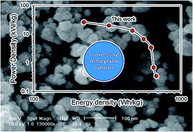
Using nanoparticles, instead of microparticles, as active electrode materials in lithium ion batteries could provide a solution to slow charging rates due to long ion diffusion pathways in conventional bulk materials. In this work, we present a new strategy for the synthesis of high purity lithium nickel manganese oxide (LiNi0.5Mn1.5O4) nanoparticles as a high-voltage cathode. A sonochemical reaction is used to synthesize nickel hydroxide and manganese dioxide nanoparticles followed by a solid-state reaction with lithium hydroxide. The product shows a single spinel phase and uniform spherical nano-particles under the appropriate calcination conditions. The LiNi0.5Mn1.5O4 exhibits a high voltage plateau at about 4.7–4.9 V in the charge/discharge process and delivers a discharge capacity of more than 140 mA h g−1 and excellent cycling performance with 99% capacity retention after 70 cycles. The synthesized nano-particles show improved electrochemical performance at high rates. This electrode delivers a power density as high as 26.1 kW kg−1 at a discharge rate of 40 C. This power performance is about one order of magnitude higher than traditional lithium ion batteries. These findings may lead to a new generation of high power lithium ion batteries that can be recharged in minutes instead of hours.

Introduction

Lithium-ion batteries have gained enormous interest recently for large-scale applications, such as electric vehicles, hybrid electric vehicles, and stationary energy storage.1 To meet the requirements of these applications, further improvements in terms of energy and power density are required. The transition-metal-doped spinel-type LiMxMn2−xO4 (where M is Ni,2,3 Fe,4,5 Cr,6 Co,7 etc.) offers cathode materials with one of the highest potentials for high power Li batteries. The voltage plateau and capacity in a Li/LiMxMn2−xO4 cell strongly depend on the type of transition metal (M) and its constituents. The charge/discharge reaction mechanism is based on oxidation/reduction of the doped transition metal above 4.6 V. Among all possible compositions, LiNi0.5Mn1.5O4 (LNMO) is the most attractive since it offers a flat plateau at 4.7 V, due to the Ni2+/Ni4+ couple, with a capacity of >130 mA h g−1, and good cycling stability and rate capability.8–22

There are two possible lattice structures for LNMO depending on the Ni ordering in the lattice.13,23 One is primitive simple cubic (P4332), and the other is face centered spinel (Fd[3 with combining macron]m). The structural differences between these two space groups are described in the ESI.

To meet the high power demands of lithium ion batteries in new applications, the rate capability of LNMO needs to be significantly improved. To reach this goal, two methods can be used: (1) increasing the electronic conductivity by controlling of the electrode microstructure, or (2) enhancing the Li-ion transport by reducing the bulk diffusion length in the active phase, which can be achieved by the use of nanostructured materials. The relatively low conductivity is one of the main drawbacks of LNMO, restricting its high-rate performance. To enhance conductivity, nanosized LNMO materials have been synthesized by various methods to shorten the transport length of Li+ ions and electrons, and improved high-rate performances have been achieved.24–27 Different methods of synthesis can result in LNMO with different sizes, morphologies, crystal structures and electrochemical properties23,24,28–30 (Table S2). Brutti and coworkers investigated various synthesis methods for the LNMO spinel including: wet chemistry, solid state reactions, combustion synthesis, cellulose-based sol–gel synthesis, ascorbic acid-based sol–gel synthesis and resorcinol/formaldehyde-based sol–gel synthesis for applications as cathode materials in lithium ion batteries.30 Most of these methods include two or more steps which involve the preparation of precursors at low temperatures followed by heating at high temperatures to obtain LNMO. However, the use of expensive raw materials and the presence of impurities and aggregations in the products remain challenging.

Nanostructured materials can provide new solutions for a variety of applications31 For example, our research group has used nanomaterials to enable a new generation of batteries,32–35 supercapacitors,36–41 sensors42–45 and solid phase microextraction systems.46 In this work, we show that by engineering the structure of LNMO at the nanoscale, it is possible to fabricate high power lithium batteries that can be charge/discharged at high rates up to 40 C (where 1 C rate represents a one-hour complete charge or discharge). A single phase LNMO product with space group P4332 that did not contain nickel oxide impurities was obtained with the appropriate synthesize conditions, i.e. calcination temperature and time, were employed. These electrodes demonstrate stable and highly reversible capacity of about 141 mA h g−1 while providing higher voltage than the traditional manganese-only LiMn2O4 electrodes. In addition, this nano-sized and ordered LNMO offers high rate performance, flat voltage plateau and good cycling stability, which is an important step towards the successful utilization of high-voltage spinels for the next generation of lithium ion batteries.

Experimental section

Apparatus

A multiwave ultrasonic generator (Sonicator® 3000; Misonix, Inc., Farmingdale, NY, USA), equipped with a converter/transducer and titanium oscillator (horn), 12.5 mm in diameter, operating at 20 kHz with a maximum power output of 600 W, was used for the ultrasonic irradiation. The ultrasonic generator automatically adjusted the power level. The wave amplitude in each experiment was adjusted as needed. A cylindrical two-walled glass cell with an interior volume of 300 mL was used for the sonication of the reaction solution. The solution temperature was kept constant by circulating water from a water bath (Optima, Tokyo, Japan). A home-made centrifuge, with a maximum speed of 8000 rpm, was used for the deposition of the dispersed nano-particles. For milling precursors, a Retsch mixer/mill (RM 100) was employed. An electrical furnace (Paragon E10, USA) was used to heat the samples. X-ray diffraction (Cu Kα, λ = 1.5406 A°) (Philips X'pert diffractometer), and scanning electron microscopy (SEM) (Philips XL 30) were used to characterize the as-prepared powders. The cyclic voltammetry (CV), electrochemical impedance spectroscopy (EIS) measurements were carried out using Galvanostat/PotentiostatAutolab (PGSTAT30) connected to a PC. Electrochemical charge/discharge experiments were performed on a Solartron SI 1470.

Synthesis of nano-LNMO particles

Sonochemical synthesis of Ni(OH)2 was carried out as previously reported.32 Briefly, 100 mL of 0.1 M NiCl2·6H2O and 0.8 mM CTAB were prepared and sonicated for 5 min in a sonication flask. Then, 100 mL of 0.2 M NaOH was added dropwise into the sonication flask over 45 min. The precipitate was allowed to settle for 2 h and the colloidal suspensions were centrifuged and washed with distilled water. The precipitate was dried to a constant weight (24 h) in an oven at 70 °C and characterized as Ni(OH)2. Nano-particles of MnO2 were prepared by an oxidation reaction under ultrasonication based on previous reports.33,35 Briefly, nano-particles of γ-MnO2 were synthesized by a redox reaction between stoichiometric quantities of MnSO4·H2O and (NH4)2S2O8 in the presence of an ultrasonic wave.

LNMO nano-particles were synthesized using a stoichiometric amount of LiOH, nano-Ni(OH)2, and nano-MnO2 (2.12[thin space (1/6-em)]:[thin space (1/6-em)]1[thin space (1/6-em)]:[thin space (1/6-em)]3) which were thoroughly mixed using a Retsch mixer/mill for 1 h. Next, the mixtures were calcined at 800 °C for 24 h, and subsequently cooled to room temperature. The resulting powders were thoroughly washed several times with distilled water, centrifuged and dried for 24 h in oven at 100 °C. Scheme S1 shows a schematic representation of the preparation of the LiNi0.5Mn1.5O4 nanostructures.

Electrochemical investigations

The electrochemical performances of the as-prepared powders were investigated with a beaker-type three-electrode cell. The working electrode was composed of 80% LNMO, 15% carbon (Merck) and 5% Teflon (polytetrafluoroethylene) (a 60% water-based solution from SUTECH, Iran) binder by weight. This blend was rolled and pressed onto a nickel grid current collector, and the electrode was dried at 120 °C for 12 h in an oven. In a typical experiment, the active mass loading is between 8 and 9 mg. The three-electrode cell consisted of an LNMO working electrode and a pressed Li granule (Fluka) on a Ni grid current collector used for the electrochemical measurements both as a counter and a reference electrode. The electrolyte was 1 M LiClO4 (Acros) in propylene carbonate (PC) (Merck). The assembly of the cells was carried out in a dry Ar-filled glove box. CV and EIS experiments were done in three-electrode systems. The cyclic voltammogram was measured at a sweep rate of 0.1 mV s−1 between 3.5 and 5.0 V. The EIS experiments were performed at different applied voltages (4.3–5.0 V) over a frequency range of 100 kHz to 10 mHz with a perturbation amplitude of 5 mV. EIS data analyses were carried out based on the CNLS method of Boukamp using Zview2 software (Scribner Associates), with an appropriate equivalent circuit as described in the text. It should be noted that in all cases, the uncertainty in data fitting was approximately <10%. Galvanostatic charge/discharge measurements were performed in a two-electrode system within a potential range of 4.5–5.0 V versus Li/Li+. This electrochemical cell is composed of a LNMO cathode, 1 M LiClO4 in PC as the electrolyte, and lithium metal as the anode. All the electrochemical tests were done at 25 °C.

Results and discussion

Characterisation of LNMO

Crystal and morphological studies. The crystal structure of the LNMO particles was examined by XRD as shown in Fig. 1a. The pattern is typical of the spinel structure,47 indicating no impurities present in the compound. This is very important because in synthesizing LNMO, impurities such as NiO and LixNiyO usually exist in the products, which can deteriorate their electrochemical performance.48,49 All these peaks indicate a primitive simple cubic structure (JCPDS#802184) with the space group P4332 (ref. 50,51) (Fig. 1b). In this space group Li atoms are in 8c sites, Ni atoms in 4b sites, Mn atoms in 12d sites, and O atoms in 8c and 24(e) sites.51,52 As previously mentioned, the crystal structure has a significant effect on electrochemical properties. LNMO with the Fd[3 with combining macron]m space group has two distinct plateaus during the charge and discharge process around 4.7 V corresponding to the Ni2+/4+ redox couple.53 For the P4332 space group, these two plateaus are not readily observed.
image file: c5ra08170j-f1.tif
Fig. 1 (a) X-ray diffraction patterns (b) LNMO with P4332 space group (c) scanning electron micrograph of prepared LNMO.

Scanning electron microscopy (SEM) shows that the LNMO possesses uniform particles with semispherical-like shapes and a particles size between 20–50 nm, Fig. 1c. These nanoparticles are composed of nondistinct grains with a rough surface and large porosity, which could facilitate the diffusion of electrolyte into the electrode materials during charge and discharge processes.

Electrochemical investigations. Fig. 2a displays a cyclic voltammogram of a LNMO electrode at the scan rate of 0.1 mV s−1 in the voltage range of 3.5–5.0 V versus Li/Li+ in a 1 M LiClO4 in propylene carbonate electrolyte. Two resolved peaks at 4.72 (a1) and 4.78 V (a2) on the forward scan, and two peaks at 4.71 (c2) and 4.66 V (c1) on the reverse scan are observed. This operating potential is higher than the undoped spinel LMO (a1 = 3.95, a2 = 4.18, c1 = 3.92, c2 = 4.15 V),33 indicating the importance of Ni2+ ion doping. The higher potential of LNMO can be attributed to the removal of two electrons occupying the position of the Ni2+ 3d eg levels with respect to the Mn4+ 3d eg levels with no electrons. Accordingly, the eg level of Ni2+ filled with two electrons is about 0.5 eV higher than the empty Mn4+ eg level, leading to an increase of the operating voltage.54 The two sets of redox couples appearing in the CV profiles correspond to distinct redox voltages for Ni2+/Ni3+ and Ni3+/Ni4+ as reported by others.55 The potential difference between the peaks in each of these redox couples are 0.06 and 0.07 V, which suggests the redox system is reversible. In LNMO, Ni2+ exists at the 16d site, instead of Mn3+, and their redox reactions are related to the Li-ion extraction/insertion at 5 V.4 For stoichiometric LNMO, all Ni exists in the 2+ oxidation state and all Mn exists in the 4+ oxidation state, resulting in the absence of the 4 V potential plateau.33,52 In other words, in LNMO nickel rather than manganese is involved in the electrochemical redox reactions.
image file: c5ra08170j-f2.tif
Fig. 2 (a) Cyclic voltammogram of the LNMO at the scan rate of 0.1 mV s−1 in 1.0 M LiClO4 at 25 °C. (b) Potential effect on Nyquist plots of LNMO nano-particles electrodes at different applied voltages (inset is its equivalent circuit).

The presence of manganese in the redox reactions increases the possibility of Jahn–Teller distortion,56 and may thus reduce the life cycle. The cathode showed very stable electrochemical performance without any noticeable degradation of the electrolyte solution in the operational potential range of this electrode during cycling tests. Electrochemical impedance spectroscopy (EIS) could help provide an understanding of the electrochemical behavior of the LNMO electrodes. Fig. 2b displays Nyquist plots of a LNMO electrode at different applied voltages (4.3–5.0 V). The applied voltage values were selected carefully to test the electrochemical behavior of the electrodes before and after the intercalation of lithium ions. As shown in Fig. 2b, all Nyquist spectra are comprised of a semicircle in the high frequency range, another semicircle in the medium-to-low frequency range and a sloping line at the low frequency range, being attributed to the resistance of Li+ ion migration through the surface layer, charge transfer resistance, and diffusion of Li+ in the solid electrode, respectively.57,58 The impedance spectra can be explained on the basis of an equivalent circuit which is presented as an inset of Fig. 2b.59 In this circuit, RS is the electrolyte resistance, RSEI is the solid electrolyte interface, Rct is the charge transfer resistance, W is the Warburg impedance, and CPESEI and CPEdl are constant phase elements. The solution resistance (RS) and solid electrolyte interface (RSEI) resistance changed only slightly because the electrolyte and the surface film were stable during cycling for the cell and they are nearly potential-independent.60 In contrast to the resistance of the solid electrolyte interface, charge transfer resistance is largely potential-dependent. As can be seen from Fig. 2b, a significant change in the diameter of the second semicircle is observed by changing the applied potential, which mainly reflects the change of charge-transfer resistance.

The charge transfer resistance fitting results are summarized in Table S1. The charge transfer resistance decreased with increasing the electrode potential from 4.3 to 4.7 V, and then increased with increasing potential from 4.8 to 5.0 V. This result is consistent with the analysis in Fig. 2a. These results show that nanostructured LNMO spinel has faster Li-ion and electron transport at the interfaces between the electrolyte and the electrodes and shows its improved performance at higher voltage than nanostructured LMO which was previously reported by our group33 (for LMO Rct = 10 Ω cm2 at operating voltage of 4.1 V and for LNMO Rct = 7 Ω cm2 at operating voltage of 4.7 V).

The initial charge and discharge curves of LNMO are illustrated in Fig. 3. The charge curves exhibit a very flat voltage profile at around 4.7 V region, which is attributed to the oxidation of Ni2+ first to Ni3+ and Ni3+ then to Ni4+ during charging.61 In this study, the charge/discharge process was carried out over a narrow potential window of 0.5 V and this is where the specific capacities were calculated in this work, while the capacities reported in Table S2 are often the result of a larger potential range of 1.5 V. It has been previously demonstrated that LNMO with a disordered structure (Fd[3 with combining macron]m) shows two obvious voltage plateaus at around 4.7 V,3,52,62,63 while that with an ordered structure (P4332) gives a flat voltage profile at around 4.7 V.51 Therefore, the observation of one distinct plateau at about 4.7 V, in Fig. 3 confirms the ordered structure of LNMO and is consistent with the XRD analysis. The initial specific charge and discharge capacities are 143.1 and 140.6 mA h g−1, respectively, and therefore the columbic efficiency is greater than 98%.


image file: c5ra08170j-f3.tif
Fig. 3 Charge/discharge of LNMO spinel with rate of 0.5 C in 1.0 M LiClO4 at 25 °C.

Because LNMO spinel is used primarily for high power applications, the rate of lithium intercalation–deintercalation is especially important. Fig. 4a shows the electrode response at various C-rate currents. The charge current density was kept at a constant rate of 1 C, while the discharge currents were changed from 0.5 C to 1, 5, 10, 20, 30 and 40 C in subsequent cycles. The discharge capacities and power densities at different C rates are shown in Fig. 4b. The power densities were calculated from the following equation:64

 
P = i × Vmid (1)
Where i is discharge current density and Vmid is the midpoint voltage of the discharge plot. Fig. 4b shows the excellent rate-capability of the electrode that can operate at a rate as high as 10 C, while still maintaining 89% of the 0.5 C discharge rate capacity. Although the capacity decay is faster at higher rates, it still delivers about 50% of its initial capacity even when fully discharged in 2 min (30 C rate). This rate performance compares favorably with literature reports for ordered LNMO spinel. It should be mentioned here that the high rate performance reported in ref. 2 was only obtained in the presence of a large amount of carbon (65 wt%). The spinel LNMO studied here can provide 26 kW kg−1 based on the total mass of the active materials. Since active materials typically account for 30% of the mass of a fully packaged cell, the power density would be 7.8 kW kg−1. This power performance is higher than nickel metal-hydride (0.1–1 kW kg−1) and common lithium-ion batteries (0.8–2 kW kg−1).64 These findings indicate that the nanostructured LNMO cathode material can be used to build superior energy storage devices for HEVs and EVs offering both high-power and high-energy densities.


image file: c5ra08170j-f4.tif
Fig. 4 (a) Rate performance of the LNMO nano-particles (b) specific capacity & power vs. C rates (c) cyclic performance of the LNMO nano-particles at 0.5 C.

The excellent rate performance can be attributed to the ultrasonic cavitation that has a direct effect on the formation of the synthesized precursor. It could change the hydrolysis, condensation, nucleation and crystal growth processes.65,66 This may change the microstructure of the material and result in a more homogeneous distribution of elements in the lattice, which could in turn make full use of the charge/discharge reactions. Trivial size effects e.g. an increased surface-to-volume ratio and shorter length displacements for Li+ ions24,28,67 can also improve the rate capability and cycle life of cells.68 Furthermore, the large surface area of the electrode and electrode/electrolyte interface provide additional advantages for LNMO nanoparticles such as (1) improved reaction kinetics that results in increased development and reversibility of the lithium insertion/extraction process, which improve cell capacity and capacity retention; and (2) the ability to use high charge/discharge rates.

Fig. 4c shows the cycling performance of the LNMO electrode at 0.5 C. The LNMO electrode delivers an initial discharge capacity of 140.6 mA h g−1 and after 70 cycles the total discharge capacity is 140.1 mA h g−1, demonstrating a capacity retention >99%. We attribute this excellent cycling performance to the existence of Mn4+ alone and no impurity phases resulting from Li, Ni, and Mn atoms that are rather uniformly distributed on the atomic scale. This is also consistent with recent studies showing that unlike disordered materials, nanoscaling of ordered structures can be an effective strategy for not only higher rate capability but also better stability.14–16,69

A Ragone plot showing the energy density and power density of LNMO-based lithium ion batteries calculated based on the active mass of the electrode materials is presented in Fig. 5. As can be seen this battery can provide much higher energy density compared to conventional rechargeable batteries such as Li ion and nickel-metal hydride batteries.


image file: c5ra08170j-f5.tif
Fig. 5 Ragone plot for synthesized LNMO.

Conclusions

LiNi0.5Mn1.5O4 nanoparticles with high homogeneity, spherical morphology, and cubic structure with space group P4332 have been prepared by a two-step method: (1) sonochemical and (2) solid state reaction. The CV results showed two pair of reversible peaks at about 4.7 V. The synthesized product as a cathode material has an excellent charge and discharge efficiency. This material has the ability to discharge at high rate and high power, even up to 40 C and 26.1 kW kg−1, respectively. The LNMO nanoparticle cathode showed excellent cycle performance between 4.5 and 5.0 V, exhibiting a stable and highly reversible capacity of about 141 mA h g−1 for 70 cycles. These excellent electrochemical characteristics suggest that the nanosized LNMO particles are promising for use in high-power lithium-ion batteries.

Acknowledgements

We gratefully acknowledge the Tarbiat Modares University Research Council for supporting this work (MFM) and Nanotech Energy, Inc (RBK).

Notes and references

  1. M. Armand and J. M. Tarascon, Nature, 2008, 451, 652–657 CrossRef CAS PubMed.
  2. X. Ma, B. Kang and G. Ceder, J. Electrochem. Soc., 2010, 157, A925–A931 CrossRef CAS PubMed.
  3. H. Xia, Y. S. Meng, L. Lu and G. Ceder, J. Electrochem. Soc., 2007, 154, A737–A743 CrossRef CAS PubMed.
  4. T. Ohzuku, S. Takeda and M. Iwanaga, J. Power Sources, 1999, 81–82, 90–94 CrossRef CAS.
  5. T. Ohzuku, K. Ariyoshi, S. Takeda and Y. Sakai, Electrochim. Acta, 2001, 46, 2327–2336 CrossRef CAS.
  6. H. C. Wang and C. H. Lu, J. Power Sources, 2003, 119–121, 738–742 CrossRef CAS.
  7. Y. Shin and A. Manthiram, Electrochim. Acta, 2003, 48, 3583–3592 CrossRef CAS.
  8. Y. Terada, K. Yasaka, F. Nishikawa, T. Konishi, M. Yoshio and I. Nakai, J. Solid State Chem., 2001, 156, 286–291 CrossRef CAS.
  9. W. S. Yoon, C. P. Grey, M. Balasubramanian, X. Q. Yang and J. McBreen, Chem. Mater., 2003, 15, 3161–3169 CrossRef CAS.
  10. C. S. Johnson, J. S. Kim, A. J. Kropf, A. J. Kahaian, J. T. Vaughey, L. M. L. Fransson, K. Edström and M. M. Thackeray, Chem. Mater., 2003, 15, 2313–2322 CrossRef CAS.
  11. M. Kunduraci and R. T. S. U. o. N. J.-N. Brunswick, High power 4.7 V nanostructured spinel lithium manganese nickel oxide lithium-ion battery cathode materials, Rutgers The State University of New Jersey - New Brunswick, 2007 Search PubMed.
  12. Y. Yao, H. Liu, G. Li, H. Peng and K. Chen, Mater. Chem. Phys., 2014, 143, 867–872 CrossRef CAS PubMed.
  13. X. Zhu, X. Li, Y. Zhu, S. Jin, Y. Wang and Y. Qian, Electrochim. Acta, 2014, 121, 253–257 CrossRef CAS PubMed.
  14. J. Yang, X. Han, X. Zhang, F. Cheng and J. Chen, Nano Res., 2013, 6, 679–687 CrossRef CAS.
  15. J. Yang, X. Zhang, Z. Zhu, F. Cheng and J. Chen, J. Electroanal. Chem., 2013, 688, 113–117 CrossRef CAS PubMed.
  16. X. Zhang, F. Cheng, J. Yang and J. Chen, Nano Lett., 2013, 13, 2822–2825 CrossRef CAS PubMed.
  17. G. Derrien, J. Hassoun, S. Panero and B. Scrosati, Adv. Mater., 2007, 19, 2336–2340 CrossRef CAS PubMed.
  18. J. Hassoun, S. Panero, P. Reale and B. Scrosati, Adv. Mater., 2009, 21, 4807–4810 CrossRef CAS PubMed.
  19. J. Hassoun, P. Reale, S. Panero and B. Scrosati, Isr. J. Chem., 2008, 48, 229–234 CrossRef CAS PubMed.
  20. R. Verrelli, J. Hassoun, A. Farkas, T. Jacob and B. Scrosati, J. Mater. Chem. A, 2013, 1, 15329–15333 CAS.
  21. G. A. Elia, F. Nobili, R. Tossici, R. Marassi, A. Savoini, S. Panero and J. Hassoun, J. Power Sources, 2015, 275, 227–233 CrossRef CAS PubMed.
  22. L. Lombardo, M. A. Navarra, S. Panero, L. A. Medina, A. Matic and J. Hassoun, J. Power Sources, 2014, 245, 232–235 CrossRef CAS PubMed.
  23. Y. Idemoto, H. Narai and N. Koura, J. Power Sources, 2003, 119–121, 125–129 CrossRef CAS.
  24. J. C. Arrebola, A. Caballero, M. Cruz, L. Hernán, J. Morales and E. R. Castellón, Adv. Funct. Mater., 2006, 16, 1904–1912 CrossRef CAS PubMed.
  25. M. Kunduraci and G. G. Amatucci, Electrochim. Acta, 2008, 53, 4193–4199 CrossRef CAS PubMed.
  26. J. Gao, J. Li, C. Jiang and C. Wan, J. Electrochem. Soc., 2010, 157, A899–A902 CrossRef CAS PubMed.
  27. X. Zhang, J. Liu, H. Yu, G. Yang, J. Wang, Z. Yu, H. Xie and R. Wang, Electrochim. Acta, 2010, 55, 2414–2417 CrossRef CAS PubMed.
  28. M. G. Lazarraga, L. Pascual, H. Gadjov, D. Kovacheva, K. Petrov, J. M. Amarilla, R. M. Rojas, M. A. Martin-Luengo and J. M. Rojo, J. Mater. Chem., 2004, 14, 1640–1647 RSC.
  29. S. H. Oh, K. Y. Chung, S. H. Jeon, C. S. Kim, W. I. Cho and B. W. Cho, J. Alloys Compd., 2009, 469, 244–250 CrossRef CAS PubMed.
  30. L. H. Chi, N. N. Dinh, S. Brutti and B. Scrosati, Electrochim. Acta, 2010, 55, 5110–5116 CrossRef CAS PubMed.
  31. Y. Gogotsi, ACS Nano, 2014, 8, 5369–5371 CrossRef CAS PubMed.
  32. M. A. Kiani, M. F. Mousavi and S. Ghasemi, J. Power Sources, 2010, 195, 5794–5800 CrossRef CAS PubMed.
  33. M. A. Kiani, M. F. Mousavi and M. S. Rahmanifar, Int. J. Electrochem. Sci., 2011, 6, 2581–2595 CAS.
  34. K. Ghanbari, M. F. Mousavi and M. Shamsipur, Electrochim. Acta, 2006, 52, 1514–1522 CrossRef CAS PubMed.
  35. A. Pendashteh, M. F. Mousavi, M. A. Kiani, S. H. Kazemi and M. S. Rahmanifar, J. Iran. Chem. Soc., 2012, 9, 389–395 CrossRef CAS PubMed.
  36. H. R. Ghenaatian, M. F. Mousavi, S. H. Kazemi and M. Shamsipur, Synth. Met., 2009, 159, 1717–1722 CrossRef CAS PubMed.
  37. H. R. Ghenaatian, M. F. Mousavi and M. S. Rahmanifar, Synth. Met., 2011, 161, 2017–2023 CrossRef CAS PubMed.
  38. A. Pendashteh, M. F. Mousavi and M. S. Rahmanifar, Electrochim. Acta, 2013, 88, 347–357 CrossRef CAS PubMed.
  39. H. R. Ghenaatian, M. F. Mousavi and M. S. Rahmanifar, Electrochim. Acta, 2012, 78, 212–222 CrossRef CAS PubMed.
  40. A. Pendashteh, M. S. Rahmanifar, R. B. Kaner and M. F. Mousavi, Chem. Commun., 2014, 50, 1972–1975 RSC.
  41. A. Pendashteh, M. S. Rahmanifar and M. F. Mousavi, Ultrason. Sonochem., 2014, 21, 643–652 CrossRef CAS PubMed.
  42. M. Y. Elahi, M. F. Mousavi and S. Ghasemi, Electrochim. Acta, 2008, 54, 490–498 CrossRef CAS PubMed.
  43. K. Ghanbari, S. Z. Bathaie and M. F. Mousavi, Biosens. Bioelectron., 2008, 23, 1825–1831 CrossRef CAS PubMed.
  44. M. Yousef Elahi, S. Z. Bathaie, S. H. Kazemi and M. F. Mousavi, Anal. Biochem., 2011, 411, 176–184 CrossRef CAS PubMed.
  45. A. Mehdinia, S. H. Kazemi, S. Z. Bathaie, A. Alizadeh, M. Shamsipur and M. F. Mousavi, J. Pharm. Biomed. Anal., 2009, 49, 587–593 CrossRef CAS PubMed.
  46. A. Mehdinia, M. F. Mousavi and M. Shamsipur, J. Chromatogr. A, 2006, 1134, 24–31 CrossRef CAS PubMed.
  47. D. Li, A. Ito, K. Kobayakawa, H. Noguchi and Y. Sato, Electrochim. Acta, 2007, 52, 1919–1924 CrossRef CAS PubMed.
  48. R. Alcántara, M. Jaraba, P. Lavela and J. L. Tirado, Electrochim. Acta, 2002, 47, 1829–1835 CrossRef.
  49. Q. Zhong, A. Bonakdarpour, M. Zhang, Y. Gao and J. R. Dahn, J. Electrochem. Soc., 1997, 144, 205–213 CrossRef CAS PubMed.
  50. S. Park and Y. Sun, Electrochim. Acta, 2004, 50, 434–439 Search PubMed.
  51. K. Ariyoshi, Y. Iwakoshi, N. Nakayama and T. Ohzuku, J. Electrochem. Soc., 2004, 151, A296–A303 CrossRef CAS PubMed.
  52. J. H. Kim, S. T. Myung, C. S. Yoon, S. G. Kang and Y. K. Sun, Chem. Mater., 2004, 16, 906–914 CrossRef CAS.
  53. X. Zhang, H. Zheng, V. Battaglia and R. L. Axelbaum, Proc. Combust. Inst., 2011, 33, 1867–1874 CrossRef CAS PubMed.
  54. Q. Zhong, A. Bonakdarpour, M. Zhang, Y. Gao and J. R. Dahn, J. Electrochem. Soc., 1997, 144, 205–213 CrossRef CAS PubMed.
  55. A. Van Der Ven, C. Marianetti, D. Morgan and G. Ceder, Solid State Ionics, 2000, 135, 21–32 CrossRef CAS.
  56. H. Jiang, Y. Fu, Y. Hu, C. Yan, L. Zhang, P. S. Lee and C. Li, Small, 2014, 10, 1096–1100 CrossRef CAS PubMed.
  57. J. Liu and A. Manthiram, J. Electrochem. Soc., 2009, 156, A66–A72 CrossRef CAS PubMed.
  58. K. M. Shaju and P. G. Bruce, Dalton Trans., 2008, 5471–5475 RSC.
  59. N. Zhang, T. Yang, Y. Lang and K. Sun, J. Alloys Compd., 2011, 509, 3783–3786 CrossRef CAS PubMed.
  60. Y. Ding, P. Zhang and D. Gao, J. Alloys Compd., 2008, 456, 344–347 CrossRef CAS PubMed.
  61. K. A. Striebel, A. Rougier, C. R. Horne, R. P. Reade and E. J. Cairns, J. Electrochem. Soc., 1999, 146, 4339–4347 CrossRef CAS PubMed.
  62. Y. S. Lee, N. Kumada and M. Yoshio, J. Power Sources, 2001, 96, 376–384 CrossRef CAS.
  63. K. Takahashi, M. Saitoh, M. Sano, M. Fujita and K. Kifune, J. Electrochem. Soc., 2004, 151, A173–A177 CrossRef CAS PubMed.
  64. D. Linden and T. B. Reddy, Handbook of batteries, McGraw-Hill Companies, Inc., New York, 3rd edn, 2002 Search PubMed.
  65. K. S. Suslick, S. B. Choe, A. A. Cichowlas and M. W. Grinstaff, Nature, 1991, 353, 414–416 CrossRef CAS PubMed.
  66. D. Chaumont, A. Craievich and J. Zarzycki, J. Non-Cryst. Solids, 1992, 147–148, 41–46 CrossRef CAS.
  67. M. Kunduraci, J. F. Al-Sharab and G. G. Amatucci, Chem. Mater., 2006, 18, 3585–3592 CrossRef CAS.
  68. A. S. Aricò, P. Bruce, B. Scrosati, J. M. Tarascon and W. Van Schalkwijk, Nat. Mater., 2005, 4, 366–377 CrossRef PubMed.
  69. E. Lee and K. A. Persson, Nanotechnology, 2013, 24, 424007 CrossRef PubMed.

Footnote

Electronic supplementary information (ESI) available. See DOI: 10.1039/c5ra08170j

This journal is © The Royal Society of Chemistry 2015