Synthesis of highly stable and high water retentive functionalized biopolymer-graphene oxide modified cation exchange membranes†
Prem P. Sharmaab and
Vaibhav Kulshrestha*ab
aCSIR-Central Salt and Marine Chemicals Research Institute (CSIR-CSMCRI), Council of Scientific & Industrial Research (CSIR), Gijubhai Badheka Marg, Bhavnagar-364 002, Gujarat, India. E-mail: vaibhavk@csmcri.org; vaihavphy@gmail.com; Fax: +91-278-2566970; Fax: +91-278-2567562; Tel: +91-278-2567039
bAcademy of Scientific and Innovative Research, CSIR-Central Salt and Marine Chemicals Research Institute (CSIR-CSMCRI), Council of Scientific & Industrial Research (CSIR), Gijubhai Badheka Marg, Bhavnagar-364 002, Gujarat, India
First published on 15th June 2015
Abstract
Usage of polymer electrolyte membranes in energy based devices is substituting the conventional electrolytes. Herein, we have synthesized a PEM based biopolymer functionalized with silica modified GO and PVA. GO has been modified in two steps to synthesize silica grafted sulfonated GO. The functionalization of chitosan has been performed using 1,3-propane sultone after deacetylation. Furthermore, PVA has been used as a polymer matrix because PVA possesses good film forming property with mechanical stability. Different weight% (1, 2 and 5) of modified GO has been incorporated into the chitosan matrix. The prepared PEMs have been subjected to different types of characterization such as structural, thermal, mechanical and electrochemical characterization. The nano-hybrid membranes show significant increment in electrochemical properties. MGO–SCH-5 membrane shows a proton conductivity of 6.77 × 10⁻² S cm−1, which increases to 11.2 × 10⁻² S cm−1 at 90 °C. The thermal and mechanical stability of PEM also increases with MGO content in the sulfonated chitosan. The elastic modulus for the MGO–SCH-5 membrane is calculated to be 21.37 MPa with 54 MPa of maximum stress. Thus, these membranes may be targeted as PEMs for higher temperature energy applications.
Introduction
Polymer electrolyte membranes (PEM) are playing a vital role in energy based devices and replacing liquid electrolytes in fuel cells and batteries due to their ease of handling and excellent physico-chemical as well as mechanical properties.1–4 Composite membranes are the subject of intense research in addition to being ideal works of art due to their excellent properties.5,6 To date, various types of fillers have been incorporated into the polymer matrix to enhance the membrane performance for different applications.7–10 Different types of carbon based materials, such as carbon quantum dots, graphene oxide, C60 and carbon nanotubes, have been incorporated into the polymeric membranes, and they have displayed significant enhancement in the membrane performance. Different types of oxides and conducting polymers have also been incorporated into the PEM to enhance its applicability and stability.11,12 An ideal PEM must have high ionic conductivity, high thermal and mechanical stability and high methanol crossover resistance to be employed as a solid electrolyte for fuel cell application. The fascinating properties of graphene oxide (GO) make it a material of interest. In past few years, research on GO has considerably increased, and it can be estimated by the increasing number of publications on it.6 The applicability of GO has been realized for many applications, and many others are yet to be explored.13 The use of GO in a polymer electrolyte membrane has been made in our previous study.7 Furthermore, GO has also been modified with different metals and metal oxides by many researchers.8 The modification of GO with silica is an effective strategy to increase the stability of the material because silica is an inexpensive and abundant material. A GO–silica composite has been prepared by Klaysom et al. for electroresponsive characteristics.9 High ionic conductivity is a basic requirement for a PEM, and sulfonation is an effective way of increasing the proton conducting groups in the membrane. The sulfonation of GO enhances its ionic conductivity as well as its applicability for different applications. Hu et al. studied the proton transport through monolayer graphene and hexagonal boron nitride (hBN) and observed that the monolayers of graphene and hBN constitute a class of proton conductors with high proton conductivity, chemical and thermal stability, and resistance to H2, water and methanol, which make these membranes attractive candidates for use in various hydrogen technologies.10 Chitosan is a natural polymer obtained from chitin and used as a membrane for many applications such as water desalination and batteries.11 The sulfonation of chitosan enhanced its proton conductivity due to the addition of sulfonic acid groups. Poly(vinyl alcohol) (PVA) is a water soluble polymer and has good film forming properties; it is used as a plasticiser for membrane applications.12–15 Interaction between PVA and GO is due to the hydrogen bonds, which may remarkably improve its properties. The main drawback of PVA is that it dissolves in water; to overcome this problem, PVA can be cross-linked with formaldehyde.We report the synthesis and electrochemical properties of silica modified sulfonated GO and sulfonated chitosan based PVA membrane as polymer electrolyte membranes. Different concentrations of modified GO have been incorporated within the chitosan matrix to prepare various hybrid membranes. The hybrid membranes show better electrochemical properties with higher stability and may prove to be good candidates for PEMs.
Experimental
Materials and methods
Chitosan with medium molecular weight, (3-aminopropyl)triethoxysilane (APTEOS), N,N′-dicyclohexylcarbodiimide (DCC) and graphite were purchased from Sigma Aldrich. Acetic acid with average molecular weight = ∼60.05 and density = ∼1.048–1.050 g ml−1 was purchased from Fischer Scientific. 1,3-Propane sultone with average molecular weight = ∼122.14 was purchased from TCI. The entire reaction was carried out in deionized water. All other chemicals were obtained commercially and used as received without further purification.Synthesis of graphene oxide (GO) and modified graphene oxide (MGO)
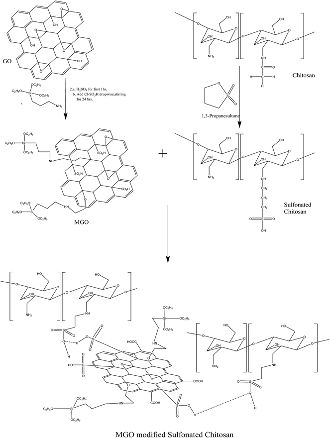
Graphene oxide was prepared from graphite powder by the modified Hummers method reported earlier.16,17 Herein, GO was converted into MGO by a two-step process. First, the reaction of graphene oxide was carried out with (3-aminopropyl)triethoxysilane. Then, the sulfonation of APTEOS modified GO was carried out using concentrated sulfuric acid followed by chlorosulfonic acid. Briefly, 100 mg of graphene oxide and 5 mg of DCC were added to 10 ml of APTEOS followed by sonication for 60 minutes. Subsequently, the entire mixture was transferred into a 100 ml round bottom flask and refluxed at 70 °C with continuous stirring for 24 h under a nitrogen atmosphere. Then, the mixture was allowed to cool and precipitate in absolute ethanol.18 The solution was centrifuged several times. Finally, the product was dried at 60 °C in vacuum overnight. Furthermore, APTEOS modified GO was sulfonated using concentrated sulfuric acid followed by chlorosulfonic acid.17 Briefly, 100 mg of APTEOS modified GO was treated with 75 ml of concentrated sulfuric acid for at least for 1 hour and then 15 ml of chlorosulfonic acid was added dropwise. The entire reaction was stirred at room temperature for 24 h. Subsequently, the solution was slowly added to diethyl ether at 0–5 °C. The entire reaction mixture was then centrifuged at 6000 rpm to obtain the desired product. The product was then dried under vacuum at 60 °C overnight. This product was designated as MGO, as shown in Scheme 1.Synthesis of sulfonated chitosan and their membranes
The chemical reaction of deacetylated chitosan with 1,3-propane sultone was carried out to obtain pendent sulfonated chitosan. The resultant product was denoted as chitosan-N-propyl sulfonic acid.19 Briefly, 1 g of chitosan was mixed with 80 ml of 2 wt% acetic acid and the reaction mixture was stirred at room temperature for 1–2 hours to obtain a homogeneous mixture. Then, 0.4 g of 1,3-propane sultone was added dropwise and the mixture was stirred at 65–70 °C for 6 hours. After cooling the reaction mixture to room temperature, it was poured into acetone. The product was chitosan-N-propyl sulfonic acid. Then, the product was dried under vacuum at room temperature and was designated as SCH, as shown in Scheme 1. The FTIR spectrum of sulfonated chitosan is shown in Fig. S1.†The MGO–SCH based hybrid membranes were obtained by obtaining a homogeneous mixture of sulfonated chitosan and MGO in deionized water. Graphene oxide has abundant oxygen in the form of –OH (hydroxyl), –COOH (carboxyl), and epoxy ring functional groups, which make GO more hydrophilic; moreover, its dispersion in deionized water is stable. Briefly, 3 g of sulfonated chitosan was mixed with deionized water at room temperature. In addition to this mixture, 3 g of poly(vinyl alcohol) was mixed with deionized water. Subsequently, both the reaction mixtures were mixed together until the mixture became homogeneous. Membranes with various MGO concentrations (1%, 2% and 5%) with sulfonated chitosan were prepared successfully and designated as MGO–SCH-1, MGO–SCH-2 and MGO–SCH-5, respectively. Briefly, the desired amount of MGO was added to the homogeneous mixture of poly(vinyl alcohol) and sulfonated chitosan in deionized water. Then, this reaction mixture was subjected to continuous stirring until a stable dispersion of MGO particles within the matrix was obtained. Subsequently, this solution was casted onto a clean glass plate. It was dried at 80 °C overnight and peeled off with the help of a sharp blade. Then, the resultant dried film was further subjected to crosslinking with formaldehyde to convert it into a water insoluble material. In a typical crosslinking reaction, the films were immersed in a solution containing formaldehyde (55.0 g), sodium sulfate (150.0 g), sulfuric acid (125.0 g) and water (470.0 g) for 3 h at 60 °C.
Chemical and structural characterization of hybrid membrane
The chemical and structural characterization of the materials and membranes was performed using 1H NMR, FTIR, XRD, TEM and AFM. The Fourier transform infrared spectra (FTIR) of the MGO and MGO–SCH hybrid were recorded at frequencies of 4000–400 cm−1 using KBR pellets with the help of a Spectrum GX series 49387 spectrometer. The X-ray diffractions of GO, MGO and MGO–SCH membrane were obtained using a Philips X'Pert MPD system using Cu Kα radiation with a scattering range of 5–60°. Transmission electron microscopy was carried out using a JEOL, JEM 2100 microscope with an accelerating voltage of 200 kV. The surface roughness was recorded using atomic force microscopy (AFM) in a semi-contact mode on a NTEGRA AURA (NTMDT).Thermal and mechanical stabilities of hybrid membrane
Thermal behaviors of MGO and MGO–SCH in terms of degradation and stability were measured with the help of thermogravimetric analysis (TGA) under a N2 atmosphere on a Mettler Toledo TGA/SDTA851e with STARe software with a heating rate of 5 °C min−1 from 25 to 600 °C. The glass transition behavior of each hybrid membrane was assessed through differential scanning calorimetry (DSC) using a Mettler Toledo DSC822e thermal analyzer under a temperature range of 0–200 °C. A universal testing machine (UTM) was used to assess the mechanical properties of the hybrid membranes at room temperature.Physiochemical and electrochemical characterization of hybrid membrane
Water uptake behaviour of the membranes was determined by recording the weight gain after equilibrating in water for 24 h. Ion exchange capacity of the hybrid membranes was estimated by acid–base titration. The proton conductivity of the membranes was measured on a potentiostat/galvanostat (Auto Lab, Model PGSTAT 30). Proton diffusion coefficient for each membrane was calculated using the conductivity measurements of the membranes. Details of the experiments are given in ESI.†Methanol crossover resistance
Methanol permeability for the membranes was evaluated by the measurement with a two-compartment cell. Details of the experiment and formula used are described in the ESI section.†Results and discussion
Chemical and structural characterization of MGO and hybrid membranes
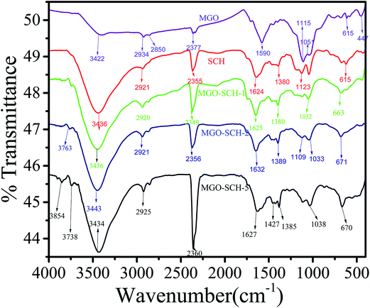
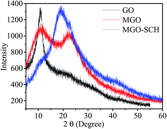
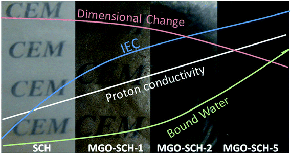
The interaction between SCH and MGO is shown in Scheme 1. It is clear from the scheme that SCH is attached to MGO with hydrogen bonding. The FTIR spectra of MGO, SCH and hybrids of MGO and SCH are presented in Fig. 1. The IR spectra of the prepared materials and hybrids show a broad peak at 3420–3434 cm−1, which is due to the existence of large number of hydroxyl and amino groups. The bands near 1622 cm−1 are due to the presence of the stretching of acetyl groups present in chitosan. The absorption bands for sulfonic acid hydrate appear nearly from 2400 to 2000 cm−1, and the characteristic peaks of –OH, –SO3H and amide groups appear at 3434, 2918, and 1625 cm−1, respectively.20 IR peaks in the region of 1552–1535 cm−1 indicate the occurrence of sulfonation of the amino group present in the chitosan. The peak at 1115 cm−1 for MGO demonstrates the presence of a –SO3H functional group.17,21 The appearance of a narrow peak near 1051 cm−1 (Si–O–C/Si–O–Si) demonstrates the evidence of the successful chemical functionalization of graphene sheets.22 Moreover, the FTIR results clearly indicate the formation of MGO and MGO–SCH nano-hybrid membrane. 1H NMR spectrum of the sulfonated chitosan hybrid membrane is shown in Fig. S2.† 1H NMR allows us to predict the substitution of the chitosan. The enhanced chemical shift values for the peaks at 3.41 and a minor peak at 3.18 indicate the reduction of the free amino groups.23 This decrease in the free amine group signal indicates that the substitution takes place on the free primary amine. The diffused peaks near 2.3 ppm are due to the overlapping of the signals appearing due to the overlapping of –OH and –NH groups. The structural analyses of GO, MGO and MGO–SCH hybrid membranes are shown in Fig. 2. GO has diffraction angle and inter-planar spacing values of 11.16° and 7.92 Å, respectively. On the other hand, in the case of MGO, two values of the diffraction angle are found; the second being at 22.41°, and a shift in the value of the diffraction angle is greater than that of GO and determined to be 11.92°, which is a result of the partial rearrangement through π–π interactions and the removal of oxygen functional groups and also due to the insertion of the sulfonic acid group in the GO.24 The interaction of MGO with biopolymer can be seen in the figure where the value of the diffraction peak is determined to be 19.44°. Fig. 3 shows the TEM images of GO and MGO at different magnifications. The sheet-like structure of GO can be seen in Fig. 3(A), while Fig. 3(B) shows the micrograph of the modified GO. Uniformly distributed Si nanoparticles of 4 nm can be seen throughout the GO matrix. Fig. 3(C) shows the MGO at higher magnifications. Average roughness of the SCH and MGO–SCH hybrid membranes was calculated using AFM imaging. The average roughness of the membranes was found to be 4.254 nm in the case of the SCH membrane and 7.835 nm for the MGO–SCH hybrid membrane. The respective AFM images are shown in Fig. 4. The transparency of the hybrid membrane is decreased by the addition of a certain amount of MGO into the SCH and can be seen in Fig. 9.Stability of MGO and hybrid membranes
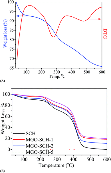
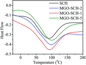
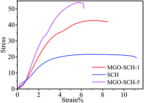
The thermal stability of MGO and membranes are presented in Fig. 5. Fig. 5(A) shows the TGA and DTG thermograph of MGO. Two steps in weight loss are observed from the spectrum; one is due to the degradation of the sulfonic acid group and the other is due to the degradation of Si. Thermal degradation study of the chitosan and MGO–SCH based nano-hybrid membranes are presented in Fig. 5(B). Thermal studies show three stages of decomposition. First, loss in the weight is measured due to the vaporization of the moisture content. Second stage weight loss is due to the breaking of bonds established due to the functional groups that may be volatile as well. Third stage breakdown is due to the disintegration of the polymer backbone. The loss at the first stage is nearly 11% in the range of 80–200 °C, and the second stage consists of a weight loss of about 25% at the temperature just above 250 °C, which is due to the pendent sulfonic acid groups present in the chitosan. Similarly, the third stage weight loss of 75% is found in the region of about 450–550 °C and is due to the breaking of the chitosan skeleton.24 The DSC thermograms of SCH and MGO–CHT based hybrid membrane are shown in Fig. 6. It can be seen from the figure that the Tg of the hybrid membranes increases with MGO content in the matrix and the MGO–SCH-5 membrane shows the highest thermal stability compared to the other membranes, which is also verified by TGA analysis.25The good dispersion of MGO within the polymer matrix indicates a good augmentation. To obtain the desired result, a tensile test was performed on all the polymer electrolyte nano-hybrid membranes. A typical stress–strain curve was obtained for each membrane and their mechanical properties were compared, as shown in Fig. 7. It can be seen in the figure that the incorporation of MGO into the polymer matrix in MGO–SCH-5 makes the polymer–electrolyte membrane more mechanically stiff and stable compared to the SCH membrane. The value of the elastic modulus increases in an interesting manner from SCH to MGO–SCH-5 as 8.66 MPa to 21.37 MPa, as presented in Table 1. On the other hand, the maximum stress of the hybrid membranes also increased from 21.64 MPa to 54 MPa. We can conclude that as the concentration of MGO increases from 1% to 5%, the stiffness of the membrane will also become superior. Therefore, the elongation of the hybrids with higher concentration will be found to be lesser than that of SCH. The maximum elongation at break (strain%) of 19.61% is found for SCH, which decreases by 68% and reaches 6.2% for the MGO–SCH-5 membrane, as presented in Table 1. The interfacial interaction of the MGO with the polymer matrix restricts the polymer chain movement, making the membrane too brittle. Thus, this consistency in results helps us to predict the very good interaction of the filler with that of the polymer matrix, which contributes to the increased mechanical strength of the polymeric electrolyte membrane.
| Membrane type | Young's modulus (MPa) | Maximum stress (MPa) | Elongation at break (%) |
|---|---|---|---|
| SCH | 8.66 | 21.64 | 19.61 |
| MGO–SCH-1 | 16.55 | 42.73 | 8.5 |
| MGO–SCH-5 | 21.37 | 54.0 | 6.2 |
Water uptake behaviour, water retention capability and ion exchange capacity (IEC) of hybrid membranes
Water retention capability and water uptake play a very important role for synthesising a PEM and its further application in energy devices. Water uptake as observed in the prepared membrane shows an increasing trend from SCH to MGO–SCH-5. The SCH membrane displays 27% water uptake and increases with increasing MGO content. 43% water uptake is observed by the MGO–SCH-5 membrane (Table 2). Higher water uptake in the membrane leads to higher proton conduction in the PEM. Bound water and free water values are also obtained from TGA curves. It is evident from Table 2 that bound water increases as the MGO content increases. The SCH membrane contains 0.45% bound water, which increases to 0.96% after the addition of 5 wt% MGO to the membrane. Furthermore, the calculated free water is also found to be highest in the MGO–SCH-5 membrane, i.e. 42.04%. Bound and free are the two types of water present in a membrane. Bound water is more responsible for the proton conduction in the PEM at higher temperatures. Higher water uptake leads to dimensional instability in the PEM, but in the present case dimensional stability increases with water uptake. This may be due to the interaction between SCH and MGO.5,6| Membrane type | IEC (meq g−1) | W (%) | Bound water (%) | Free water (%) | Dimensional change (%) | φ × 10−2 (S cm−1) | Pm × 10−6 (cm2 s−1) | Sp × 104 |
|---|---|---|---|---|---|---|---|---|
| SCH | 1.56 | 27 | 0.45 | 26.55 | 38.14 | 3.28 | 2.60 | 1.26 |
| MGO–SCH-1 | 2.08 | 30 | 0.50 | 29.50 | 28.57 | 4.91 | 1.90 | 2.58 |
| MGO–SCH-2 | 2.40 | 36 | 0.63 | 35.37 | 25.73 | 4.97 | 1.60 | 3.1 |
| MGO–SCH-5 | 2.56 | 43 | 0.96 | 42.04 | 24.48 | 6.77 | 1.01 | 6.71 |
IEC is the key parameter for the performance of a proton exchange membrane (PEM) and mainly depends upon the degree of functionalization of the polymer. Higher number of functional groups leads to higher IEC in a PEM. The SCH membrane shows a 1.56 meq g−1 IEC value, which increases to 2.08 meq g−1 for the MGO–SCH-1 membrane and finally attains a value of 2.56 meq g−1 for the MGO–SCH-5 membrane; the value for MGO–SCH-5 is 25% higher than that of the SCH membrane (Table 2). Thus, it can be seen that the IEC value gradually increases with increase in the MGO loading within the membrane matrix. This is due to the free carboxylic group present within the polymer matrix. The sulfonic acid group channels inside the polymer matrix and interfacial interaction between the –COOH group of the MGO and –SO3H group of the sulfonated chitosan make the whole hybrid more hydrophilic, thus providing a capacity in favour of the counter ion passing through it, and thus a gradual increase in the capacity to exchange the ions.
Effect of temperature on ionic conductivity of hybrid membranes
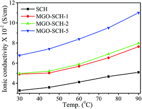
Membrane proton conductivity was measured for all the hybrid membranes from 30 to 90 °C, and the corresponding values are illustrated in Fig. 8 & Table 2. The proton conductivity increases with MGO content in the membranes due to enhanced proton mobility resulting from the increased water retention capability. The proton conductivity of the SCH membrane is calculated to be 3.28 × 10⁻² S cm−1 at 30 °C, which is increased to 6.77 × 10⁻² S cm−1 for the MGO–SCH-5 membrane. The comparison of ionic conductivity of the reported membranes is presented in Table 3. The increment in conductivity is due to the higher IEC, higher water retention capacity and higher number of available sulfonic group sites in the membrane. High IEC provides more acidic groups inside the membrane, and a large presence of bound water facilitates the proton diffusion.26–29 The acidic functional groups (–SO3H) of the PEM dissociate due to hydration and allow transport of the hydrated proton (H3O)+. For higher temperature applications, the membranes are tested for their conductivity from 30 to 90 °C, and it was found that temperature can moderate the conduction of protons. As the temperature increases, the migration of ions becomes faster, resulting in increment in conductivity of the hybrid membrane. The membrane conductivity was found to be increased from 1.55 to 1.63 times for SCH to MGO–SCH-5 membrane upon increasing the temperature from 30 to 90 °C. The increment in proton conductivity at higher temperatures may be due to the increment in proton migration.30,31 In the case of the MGO–SCH-5 membrane, the conductivity is comparable with a Nafion-117 membrane over the whole temperature range.32Methanol permeation (Pm) of hybrid membranes
Low methanol permeation with high proton conductivity is the basic requirement for PEM for DMFC application. The methanol permeability of SCH and MGO–SCH hybrid membranes are presented in Table 2. It is clear from the data that methanol permeation resistance of the hybrid membrane increases with MGO content in the SCH matrix. The methanol permeation resistance of the SCH membrane is found to be 2.6 × 10⁻⁶ cm2 S−1, which decreases to 1.01 × 10⁻⁶ cm2 S−1 for the MGO–SCH-5 hybrid membrane; the selectivity of the membrane is found to be enhanced by 5.3 times from its initial value of 1.26 × 10⁴ for SCH membrane. The low methanol permeability and high selectivity of the MGO–SCH-5 membrane makes it applicable for DMFC.Conclusion
In summary, we designed a biopolymer PEM having superior performance based on sulfonated chitosan as a functionalized biopolymer and modified graphene oxide with stable thermal and mechanical properties. The properties of the membranes are summarized in Fig. 9. The modified graphene oxide shows an extensive interfacial interaction with the sulfonic acid group of the biopolymer, resulting in the formation of strong chemical bonding. This provides good mechanical strength and stiffness to the PEM. The MGO–SCH-5 membrane shows good value of modulus of 21.37 MPa with 54 MPa of maximum stress and good ion-exchange capacity of 2.56 meq g−1. The MGO–SCH-5 membrane shows the stability at temperatures as high as 300 °C with better electrochemical performance. The proton conductivity of the MGO–SCH-5 membrane is calculated to be 6.77 × 10⁻² S cm−1, which increases to 11.2 × 10⁻² S cm−1 at 90 °C. The maximum ionic conductivity has been found in the MGO–SCH-5 hybrid membrane with higher methanol crossover resistance and selectivity. The synergistic approach can be derived for these membranes in the promising area of energy conservation and for high temperature polymer electrolyte cells. Moreover, the materials used to make these membranes are eco-friendly, non-hazardous, economically cheap and naturally abundant.Acknowledgements
Author V. Kulshrestha is thankful to the Department of Science and Technology, New Delhi, for providing fund under WTI scheme. Financial support received from CSIR Network projects no. CSC 0105 is also acknowledged. Authors are also thankful to Analytical Division and Centralized Instrument facility, CSMCRI, Bhavnagar for instrumental support.References
- P. P. Sharma, S. Gahlot, B. M. Bhil, H. Gupta and V. Kulshrestha, RSC Adv., 2015, 5, 38712 RSC.
- F. Lufrano, V. Baglio, P. Staiti, V. Antonucci and A. S. Arico, J. Power Sources, 2013, 243, 519 CrossRef CAS PubMed.
- K. Dutta, S. Das, P. Kumar and P. P. Kundu, Appl. Energy, 2014, 118, 183 CrossRef CAS PubMed.
- K. Xu, C. Chanthad, M. R. Gadinski, M. A. Hickner and Q. Wang, ACS Appl. Mater. Interfaces, 2009, 1, 2573 CAS.
- S. Gahlot and V. Kulshrestha, ACS Appl. Mater. Interfaces, 2015, 7, 264 CAS.
- S. Gahlot, P. P. Sharma, V. Kulshrestha and P. K. Jha, ACS Appl. Mater. Interfaces, 2014, 6, 5595 CAS.
- S. Gahlot, P. P. Sharma, H. Gupta, V. Kulshrestha and P. K. Jha, RSC Adv., 2014, 4, 24662 RSC.
- X. Li, Y. Yu and Y. Meng, ACS Appl. Mater. Interfaces, 2013, 5, 1414 CAS.
- C. Klaysom, S. H. Moon, B. P. Ladewig, G. Q. M. Lu and L. Z. Wang, J. Phys. Chem. C, 2011, 115, 15124 CAS.
- S. Hu, M. Lozada-Hidalgo, F. C. Wang, A. Mishchenko, F. Schedin, R. R. Nair, E. W. Hill, D. W. Boukhvalov, M. I. Katsnelson, R. A. W. Dryfe, I. V. Grigorieva, H. A. Wu and A. K. Geim, Nature, 2014, 516, 227 CrossRef CAS PubMed.
- F. Perreault, M. E. Tousley and M. Elimelech, Environ. Sci. Technol. Lett., 2014, 1, 71 CrossRef CAS.
- A. Kumar, S. Gahlot, V. Kulshrestha and V. K. Shahi, AIP Conf. Proc., 2014, 1591, 379 CrossRef CAS PubMed.
- M. Kumar, D. McGlade and J. Lawler, RSC Adv., 2014, 4, 21699 RSC.
- R. Sharma, N. Singh, A. Gupta, S. Tiwari, S. K. Tiwari and S. R. Dhakate, J. Mater. Chem. A, 2014, 2, 16669 CAS.
- P. B. Palani, K. S. Abidin, R. Kannan, M. Sivakumar, F. M. Wang, S. Rajashabala and G. Velraj, RSC Adv., 2014, 4, 61781 RSC.
- V. Chabot, D. Higgins, A. Yu, X. Xiao, Z. Chen and J. Zhang, Energy Environ. Sci., 2014, 7, 1564 CAS.
- D. Yu, E. Negelli, R. Naik and L. Dai, Angew. Chem., Int. Ed., 2011, 50, 6575 CrossRef CAS PubMed.
- H. Yang, F. Li, C. Shan, D. Han, Q. Zhang, L. Niu and A. Ivaska, J. Mater. Chem., 2009, 19, 4632 RSC.
- H. S. Tsai, Y. Z. Wang, J. J. Lin and W. F. Lien, J. Appl. Polym. Sci., 2010, 116, 1686 CrossRef CAS PubMed.
- J. H. Jeon, R. K. Cheedarala, C. D. Kee and I. K. Oh, Adv. Funct. Mater., 2013, 23, 6007 CrossRef CAS PubMed.
- R. Kumar and K. Scott, Chem. Commun., 2012, 48, 5584 RSC.
- X. Xie, L. Qu, C. Zhou, Y. Li, J. Zhu, H. Bai, G. Shi and L. Dai, ACS Nano, 2010, 4, 6050 CrossRef CAS PubMed.
- R. Sharma, N. Singh, S. Tiwari, S. K. Tiwari and S. R. Dhakate, RSC Adv., 2015, 5, 16622 RSC.
- P. Vongchan, W. Sajomsang, D. Subyen and P. Kongtawelert, Carbohydr. Res., 2002, 337, 1239 CrossRef CAS.
- S. Gahlot, P. P. Sharma and V. Kulshrestha, Sep. Sci. Technol., 2015, 50, 446 CrossRef CAS PubMed.
- H. Zarrin, D. Higgins, Y. Jun, Z. Chen and M. Fowler, J. Phys. Chem. C, 2011, 115, 20774 CAS.
- Y. Heo, H. Im and J. Kim, J. Membr. Sci., 2013, 426, 11 CrossRef PubMed.
- C. W. Lin and Y. S. Lu, J. Power Sources, 2013, 237, 187 CrossRef CAS PubMed.
- B. G. Choi, J. Hong, Y. C. Park, D. H. Jung, W. H. Hong, P. T. Hammond and H. S. Park, ACS Nano, 2011, 5, 5167 CrossRef CAS PubMed.
- M. Petrowsky and R. Frech, J. Phys. Chem. B, 2010, 114, 8600 CrossRef CAS PubMed.
- C. Filipoi, D. E. Demco, X. Zhu, R. Vinokur, R. Conradi, R. Fechete and M. Möller, Chem. Phys. Lett., 2012, 554, 143 CrossRef CAS PubMed.
- Z. Jiang, X. Zhao, Y. Fu and A. Manthiram, J. Mater. Chem., 2012, 22, 24862 RSC.
- V. Bhadja, U. Chatterjee and S. K. Jewrajka, RSC Adv., 2015, 5, 40026 RSC.
- B. P. Tripathi, M. Schieda, V. K. Shahi and S. P. Nunes, J. Power Sources, 2011, 196, 911 CrossRef CAS PubMed.
Footnote |
| † Electronic supplementary information (ESI) available: The detail of the chemical, structural, physio-chemical characterization and membranes stability are included as section S1 in ESI. Fig. S1 to S2 are also included in the ESI section. See DOI: 10.1039/c5ra08042h |
| This journal is © The Royal Society of Chemistry 2015 |

